EP0101164B1 - Méthode de réparation pour aubes de turbine - Google Patents
Méthode de réparation pour aubes de turbine Download PDFInfo
- Publication number
- EP0101164B1 EP0101164B1 EP83303585A EP83303585A EP0101164B1 EP 0101164 B1 EP0101164 B1 EP 0101164B1 EP 83303585 A EP83303585 A EP 83303585A EP 83303585 A EP83303585 A EP 83303585A EP 0101164 B1 EP0101164 B1 EP 0101164B1
- Authority
- EP
- European Patent Office
- Prior art keywords
- blade
- turbine blade
- turbine
- blades
- repair
- Prior art date
- Legal status (The legal status is an assumption and is not a legal conclusion. Google has not performed a legal analysis and makes no representation as to the accuracy of the status listed.)
- Expired
Links
- 230000008439 repair process Effects 0.000 title claims description 81
- 238000010438 heat treatment Methods 0.000 claims description 91
- 238000003466 welding Methods 0.000 claims description 76
- 238000000034 method Methods 0.000 claims description 63
- 239000000463 material Substances 0.000 claims description 55
- 230000008569 process Effects 0.000 claims description 32
- 229910052751 metal Inorganic materials 0.000 claims description 27
- 239000002184 metal Substances 0.000 claims description 26
- 238000005219 brazing Methods 0.000 claims description 22
- 238000004458 analytical method Methods 0.000 claims description 7
- 230000007547 defect Effects 0.000 claims description 3
- 238000005259 measurement Methods 0.000 claims description 2
- 230000003628 erosive effect Effects 0.000 description 11
- 239000011261 inert gas Substances 0.000 description 6
- 238000011065 in-situ storage Methods 0.000 description 5
- 239000002245 particle Substances 0.000 description 5
- 238000001816 cooling Methods 0.000 description 4
- 238000005336 cracking Methods 0.000 description 4
- 230000003247 decreasing effect Effects 0.000 description 4
- 238000012360 testing method Methods 0.000 description 4
- XLYOFNOQVPJJNP-UHFFFAOYSA-N water Substances O XLYOFNOQVPJJNP-UHFFFAOYSA-N 0.000 description 4
- 229910000669 Chrome steel Inorganic materials 0.000 description 3
- 238000005452 bending Methods 0.000 description 3
- 239000012535 impurity Substances 0.000 description 3
- 230000001965 increasing effect Effects 0.000 description 3
- 238000003754 machining Methods 0.000 description 3
- 230000002028 premature Effects 0.000 description 3
- 0 C1N2CCC1*2 Chemical compound C1N2CCC1*2 0.000 description 2
- VYZAMTAEIAYCRO-UHFFFAOYSA-N Chromium Chemical compound [Cr] VYZAMTAEIAYCRO-UHFFFAOYSA-N 0.000 description 2
- PXHVJJICTQNCMI-UHFFFAOYSA-N Nickel Chemical compound [Ni] PXHVJJICTQNCMI-UHFFFAOYSA-N 0.000 description 2
- 229910001347 Stellite Inorganic materials 0.000 description 2
- 239000011324 bead Substances 0.000 description 2
- 230000008901 benefit Effects 0.000 description 2
- 239000000919 ceramic Substances 0.000 description 2
- AHICWQREWHDHHF-UHFFFAOYSA-N chromium;cobalt;iron;manganese;methane;molybdenum;nickel;silicon;tungsten Chemical compound C.[Si].[Cr].[Mn].[Fe].[Co].[Ni].[Mo].[W] AHICWQREWHDHHF-UHFFFAOYSA-N 0.000 description 2
- 230000002708 enhancing effect Effects 0.000 description 2
- 238000012544 monitoring process Methods 0.000 description 2
- 230000003647 oxidation Effects 0.000 description 2
- 238000007254 oxidation reaction Methods 0.000 description 2
- 229910000760 Hardened steel Inorganic materials 0.000 description 1
- 229910045601 alloy Inorganic materials 0.000 description 1
- 239000000956 alloy Substances 0.000 description 1
- 230000004888 barrier function Effects 0.000 description 1
- 230000015572 biosynthetic process Effects 0.000 description 1
- 230000008859 change Effects 0.000 description 1
- 229910052804 chromium Inorganic materials 0.000 description 1
- 239000011651 chromium Substances 0.000 description 1
- 239000012141 concentrate Substances 0.000 description 1
- 239000004020 conductor Substances 0.000 description 1
- 230000007797 corrosion Effects 0.000 description 1
- 238000005260 corrosion Methods 0.000 description 1
- 125000004122 cyclic group Chemical group 0.000 description 1
- 230000001419 dependent effect Effects 0.000 description 1
- 238000000151 deposition Methods 0.000 description 1
- 230000000694 effects Effects 0.000 description 1
- 230000005611 electricity Effects 0.000 description 1
- 239000000945 filler Substances 0.000 description 1
- 239000007789 gas Substances 0.000 description 1
- 229910001026 inconel Inorganic materials 0.000 description 1
- 230000003993 interaction Effects 0.000 description 1
- 230000005012 migration Effects 0.000 description 1
- 238000013508 migration Methods 0.000 description 1
- 229910052759 nickel Inorganic materials 0.000 description 1
- 230000002093 peripheral effect Effects 0.000 description 1
- 239000002244 precipitate Substances 0.000 description 1
- 230000009467 reduction Effects 0.000 description 1
- 239000012858 resilient material Substances 0.000 description 1
- 239000007787 solid Substances 0.000 description 1
- 238000007711 solidification Methods 0.000 description 1
- 230000008023 solidification Effects 0.000 description 1
- 238000012546 transfer Methods 0.000 description 1
Images



Classifications
-
- B—PERFORMING OPERATIONS; TRANSPORTING
- B23—MACHINE TOOLS; METAL-WORKING NOT OTHERWISE PROVIDED FOR
- B23P—METAL-WORKING NOT OTHERWISE PROVIDED FOR; COMBINED OPERATIONS; UNIVERSAL MACHINE TOOLS
- B23P6/00—Restoring or reconditioning objects
- B23P6/002—Repairing turbine components, e.g. moving or stationary blades, rotors
- B23P6/007—Repairing turbine components, e.g. moving or stationary blades, rotors using only additive methods, e.g. build-up welding
-
- B—PERFORMING OPERATIONS; TRANSPORTING
- B23—MACHINE TOOLS; METAL-WORKING NOT OTHERWISE PROVIDED FOR
- B23P—METAL-WORKING NOT OTHERWISE PROVIDED FOR; COMBINED OPERATIONS; UNIVERSAL MACHINE TOOLS
- B23P6/00—Restoring or reconditioning objects
- B23P6/04—Repairing fractures or cracked metal parts or products, e.g. castings
- B23P6/045—Repairing fractures or cracked metal parts or products, e.g. castings of turbine components, e.g. moving or stationary blades, rotors, etc.
-
- C—CHEMISTRY; METALLURGY
- C21—METALLURGY OF IRON
- C21D—MODIFYING THE PHYSICAL STRUCTURE OF FERROUS METALS; GENERAL DEVICES FOR HEAT TREATMENT OF FERROUS OR NON-FERROUS METALS OR ALLOYS; MAKING METAL MALLEABLE, e.g. BY DECARBURISATION OR TEMPERING
- C21D9/00—Heat treatment, e.g. annealing, hardening, quenching or tempering, adapted for particular articles; Furnaces therefor
- C21D9/50—Heat treatment, e.g. annealing, hardening, quenching or tempering, adapted for particular articles; Furnaces therefor for welded joints
-
- F—MECHANICAL ENGINEERING; LIGHTING; HEATING; WEAPONS; BLASTING
- F01—MACHINES OR ENGINES IN GENERAL; ENGINE PLANTS IN GENERAL; STEAM ENGINES
- F01D—NON-POSITIVE DISPLACEMENT MACHINES OR ENGINES, e.g. STEAM TURBINES
- F01D5/00—Blades; Blade-carrying members; Heating, heat-insulating, cooling or antivibration means on the blades or the members
- F01D5/005—Repairing methods or devices
-
- Y—GENERAL TAGGING OF NEW TECHNOLOGICAL DEVELOPMENTS; GENERAL TAGGING OF CROSS-SECTIONAL TECHNOLOGIES SPANNING OVER SEVERAL SECTIONS OF THE IPC; TECHNICAL SUBJECTS COVERED BY FORMER USPC CROSS-REFERENCE ART COLLECTIONS [XRACs] AND DIGESTS
- Y10—TECHNICAL SUBJECTS COVERED BY FORMER USPC
- Y10T—TECHNICAL SUBJECTS COVERED BY FORMER US CLASSIFICATION
- Y10T29/00—Metal working
- Y10T29/49—Method of mechanical manufacture
- Y10T29/49316—Impeller making
- Y10T29/49318—Repairing or disassembling
-
- Y—GENERAL TAGGING OF NEW TECHNOLOGICAL DEVELOPMENTS; GENERAL TAGGING OF CROSS-SECTIONAL TECHNOLOGIES SPANNING OVER SEVERAL SECTIONS OF THE IPC; TECHNICAL SUBJECTS COVERED BY FORMER USPC CROSS-REFERENCE ART COLLECTIONS [XRACs] AND DIGESTS
- Y10—TECHNICAL SUBJECTS COVERED BY FORMER USPC
- Y10T—TECHNICAL SUBJECTS COVERED BY FORMER US CLASSIFICATION
- Y10T29/00—Metal working
- Y10T29/49—Method of mechanical manufacture
- Y10T29/49718—Repairing
- Y10T29/49746—Repairing by applying fluent material, e.g., coating, casting
Definitions
- the present invention relates to a method of repairing tubine blades.
- turbine blades are subject to both erosion damage and cracking due to high stress in the blade.
- the tip of a turbine blade in a rotor assembly is the part of the blade which experiences maximum velocity and is hence the part subject to the greatest erosion.
- the present invention relates primarily but not exclusively to blades used in steam turbines. Erosion or damage of steam turbine blades generally occurs following contact between the turbine blades and either particles carried by the steam or water droplets.
- Damage can occur from metal or other solid particles, for example boiler scale, entering a steam turbine with the steam flow and striking the blades. Water droplet damage is generally restricted to the final stages of a turbine. However all stages of a turbine can be affected by particle damage.
- the rate of erosion of turbine blades will be dependent upon the relative speeds between the blades and the particles or water droplets causing the erosion and it is generally the leading edge at the outer end of each blade that is most prone to erosion by impact.
- a shield at the leading edge of the outer end of the turbine blade, such a shield being made from a material harder than the blade material.
- Steam turbine blades may be made from many suitable materials, a typical example being a 13% chrome steel and the shield may be made from stellite or a suitably hardened steel. The shield may be brazed or welded to the blade.
- one accepted method of repair is to first remove the old shield and secure a new shield in place either by brazing the new shield the blade or building up a new shield by applying fused metal in a welding operation. The blade is then machined in the area of the repair to return it to its original aerofoil profile.
- Turbine rotors generally speaking have two types of blades:
- Such a method of repair enables a more satisfactory repair and increases the usable life of the blade after repair.
- the application of said substantial thermal energy is a step in the repair which may involve brazing or welding, for example, the temperature to which at least parts of the blade would be subjected during such repair step being greater than any temperature to which the blade would be subjected during its normal use.
- the method of the present invention involving controlled heating of the turbine blade prior to the application of said thermal energy and enables the problem of residual stress after repair to be reduced by increasing the temperature of the blade in the area of the repair prior to the application of said thermal energy, thereby significantly decreasing temperature gradients in the blade, high temperature gradients which occur during the application of said substantial thermal energy are believed to cause high residual stress in the blade.
- the controlled heating of the turbine blade is maintained during application of said thermal energy and it is envisaged that the controlled heating is continued after application of said thermal energy.
- the area of the turbine blade immediately surrounding the part to be repaired, and to which said thermal energy is to be applied is first heated to a temperature greater than areas of the turbine blade further removed from said part.
- the ability to be able to heat different parts of the turbine blade to different temperatures enables the provision of a temperature differential between different parts of the turbine blade to both counter expected distortion during the application of said thermal energy and also to minimise stress by heating the blade to a temperature nearer to the temperature to which the part of the blade to be repaired is likely to attain during application of said thermal energy.
- Such a provison may enable a repair to be carried out to a turbine blade in situ i.e. on a rotor or stator since, in many cases, it will not be necessary to remove the blade for subsequent heat treatment in ovens and/or treatment by mechanical forces to return the blade to its original form.
- the method of repair of the present invention has been found to be particularly suitable for many repairs requiring a welding or brazing step such as welding cracks in a blade and re-building hard metal shields at the outer end of the leading edge of a turbine blade. In many cases such repairs may be carried out without removal of the blade from its rotor or its stator as the case may be.
- the method of repair of the present invention may be applied to the repairing of a crack in a turbine blade, said method comprising the steps of:-
- Preferably said turbine blade is maintained at said first predetermined temperature during the welding process.
- Conveniently electrical heating means are provided to heat the turbine blade to the required temperature before welding takes place, during the welding process and also after the welding process to provide heat for heat treatment.
- Control of the temperature of the turbine blade by the use of electrical heating means enables satisfactory and accurate control of the desired temperatures to be achieved.
- the turbine blade When it it required to repair a turbine blade in situ it is often the case that the turbine blade is accessible only from one side thereof with respect to the welding apparatus and, preferably therefore sufficient material is removed from the damaged blade in the region of the crack to enable a satisfactory weld to be carried out only from that one side of the blade.
- a significant amount of material is removed from the region surrounding the innermost end of the crack and the welding process is commenced at that end, the enlarged hole or recess thus formed in the blade enhancing the bond between the weld material and the parent material of the blade.
- the welding process is commenced at the innermost end of the crack since the temperature of the material of the blade will be lower at the beginning of the welding process than at the end of the welding process due to the heat generated during the process itself and, since the risk of migrating imputities during welding and oxidation is increased as the temperature increases, it is undesirable to have a region where impurites may be concentrated in a central region of the turbine blade.
- material is removed from the blade in the region of the crack to form a slot in the blade, which slot is preferably tapered so that the width of the slot increases in a direction towards the edge of the blade from which the crack extends.
- the permitting of movement of the blade during the welding process assists in minimising the occurrence of stress in the turbine blade.
- the crack is repaired it may be that, even though a satisfactory repair has been made, after further use another crack may appear in another part of the parent material of the blade.
- backing means may be provided on the other side of the blade so as to provide a barrier to the inert gas and hence substantially surround the welding area with inert gas.
- a backing member is known as chill.
- further means may be provided to introduce said inert gas on both sides of the blades and conveniently said chill may be provided with a source of supply of inert gas and passages through the chill to directing gas to said welding area.
- the method of repair of the present invention provides for automatic control of the heating means for carrying out the controlled heating and it is possible once optimum values have been obtained by analysis of test repairs, to ensure that the controlled heating means applies the optimum amount of heat to different parts of the turbine blade in order to mimimise the occurrence of stress.
- the invention further provides that heat sensing means may be provided providing one or more input signals to control means to control the amount of heat supplied to the heating means and/or change the amount of heat supplied by the heating means from pre-arranged values.
- said heating means may be energised by electricity and may comprise electrically conducting elements at least partly surrounded by ceramic beads through which the heat is radiated and conducted to the turbine blade.
- Blades adjacent to the blade to be repaired may be heated to a temperature lower than that to which the blade to be repaired is heated in order to minimise forces acting between the blades and the shroud due to thermal expansion of the blade to be repaired.
- the blade to be repaired may be heated only on one side in order to predistort the blade to compensate for distortion occurring during application of considerable thermal energy.
- the blades on either side of the blade to be repaired may be heated more generally and in a manner which does not cause distortion of such blades in order that mechanical forces due to thermal expansion between the connection between the blades and the shroud and tennons is more evenly spread over a number of blades rather than being concentrated on a single or a small number of blades.
- the pre-heating of the turbine blade to be repaired may be localised to the site where considerable thermal energy is to be applied during a welding process in order to minimise thermal expansion of the blade.
- one, two or more turbine blades either side of the blade to be repaired may be heated to a temperature decreasing as the distance away from the repaired blade increases.
- the heating means may continue to apply heat during the repair of the turbine blade, but also the temperature of the turbine blade surrounding the area to be repaired may be monitored to alter the amount of heat applied by the heating means.
- the heating means may have the energy applied thereto reduced should such a reduction in temperature be desirable.
- the means for monitoring distortion or other changes in the blade both during test analysis and during a repair may also be provided, such means for example comprising strain gauges in order that bending of the blade during the repair step requiring said thermal energy may be monitored and controlled heat applied to the blade at different areas to provide an opposite bending force to minimise distortion of the blade.
- monitoring means such as strain gauges and thermocouples may feed signals to control means to automatically control the heating means to control the temperature of different parts of the blade.
- the control means may also have output signals indicating that a turbine blade is at a suitable temperature for a repair step involving the application of said thermal energy to be carried out, and then monitor the repair step to decrease or increase the temperature of the heating means and also to indicate if the repair step should cease until conditions in the blade have changed.
- Each turbine blade having throughbores 13 and 14 through which pass respectively lacing wires 15 and 16.
- the lacing wires 15 and 16 can pass either with clearance through the respective throughbores 13 or 14 of the turbine blades or may be joined thereto by welding for example.
- the purpose of the lacing wires 15 and 16 is to prevent excessive relative movement between the blades and to generally inhibit certain modes of vibration during operation of the turbine.
- Figure 1A illustrates an example of a rotorfrom a turbine, the three turbine blades 10, 11 and 12 shown in Figure 1 being three of a considerable number of blades forming the complete array in the rotor.
- the turbine blades can be made from a variety of materials depending on the function and operating conditions of the turbine.
- a typical material from which a blade in a steam turbine may be manufactured is chrome steel with approximately 13% chromium.
- Figure 3 illustrates the area where erosion is most likely to occur on the leading edge 17 of the turbine blade 10.
- the hard material is removed (i.e, by grinding) from the turbine blade bordering the leading edge 17 the amount of material being removed ensuring that all the damaged material is removed. It is then necessary to build up a new hard shield by a welding operation, the hard material may be Stellite.
- the build up of the new shield 18 involves the application of said substantial thermal energy to the turbine blade, since the shield 18 is built up by applying molten metal to the blade 10.
- the temperature to which the turbine blade, at least in the area to which the new shield 18 of hard material is to be formed is far higher than any temperature to which the turbine blade may be subjected in use.
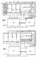
- heating mats 30, 31, 32,33,34 and 35 Prior to the welding operation to build up the new shield of 18 on the turbine blade 10, the area of the blade surrounding the part to be repaired is covered or surrounded with heating mats 30, 31, 32,33,34 and 35.
- the heating mats may be of any suitable form and may comprise, as shown in the heating mat 30, a continuous conductor 36 passing through throughbores in a large number of ceramic beads 37.
- the temperature to which different parts of the blade are heated will depend on the material from which the blade is made, the dimensions of the blade and the type of repair to be carried out.
- the blade may be heated to a temperature of about 400°C in the repair area and different parts of the blade may be heated to different either higher or lower temperatures.
- the control circuit 40 has an input 41 to supply the energy to all the heating elements such as the heating element 36 of the mat 30 and a plurality of outputs 42, 43, 44, 45, 46 and 47 so that the energy supplied to each of the heating mats 40 to 35 may be independently controlled.
- the heating control circuit 40 has an input 48 from master control unit 50.
- the master control unit 50 has a power supply 51 and may also be provided with inputs 52 to 56 from heat sensors 57 to 61 respectively.
- heat sensors 62 and 63 may be connected to inputs 64 and 65 respectively of circuit 50.
- the master control unit 50 can be programmed either manually or be supplied with recorded information from past analysis to control the signal supplied to input 48 of heating control circuit 40 so as to control each of the heating mats 30 to 35 with the amount of energy required to produce the desired temperture in the turbine blade 10.
- sensors 57 to 61 can alter the signal produced by master unit 50 to heating control 40 so as to bring the temperature into line by altering the energisation of hating mats 30 to 35 to bring the temperature to its desired value.
- the building up the new shield 18 to the turbine blade 10 by welding may take place.
- the heating mats 30 to 35 may be energised or, since the heat capacity of the blade may be considerable energisation may be terminated at this stage and the cooling process begun.
- Further heat sensors 62 and 63 may be provided which provide input signals to the master control circuit 50 at inputs 64 and 65 to alter the energisation of heating mats 30 to 35 should the actual temperature of the turbine blade sensed by sensors 62 and 63 immediately adjacent the area to be repaired either be above or below an expected value due to, for example, unexpected changes in ambient condition or the length of time taken to carry out the brazing or welding operation which may increase or decrease the expected temperature.
- Figure 7 illustrates the completed shield 18 the blade may now be subjected to further heat treatment from the heating mats 30 to 35. In some cases it may be desirable to maintain a maximum heated temperature of the blade for a certain period of time and then gradually decrease the temperature of the blade over a predetermined time period.
- machining of the blade may be carried out to return it to its original form, such machining of the blade not involving the application of said thermal energy to the blade and, therefore, requiring no further controlled heating.
- the turbine blade 60 is illustrated a turbine blade 60 having snubbers 61 and 62 on its upper side 63, there will be provided similar snubbers on the lower side 64 of the blade by means of which the blade 60 is connected to both upper and lower adjacent blades.
- the blade 60 is connected to a rotor spindle by a root 65.
- the blade 60 has a crack 66 which can be repaired by removing damaged material by grinding and then filling the groove or channel so formed with metal during a welding process.
- Heating mats 70, 71, 72 and 73 are, prior to the welding operation applied to both sides of the blade in order to heat the blade to a predetermined desired temperature.
- the mats 72 and 73 may be energised in a manner to heat the underside 64 of the blade to a temperature higher than that to which the upper side 63 is heated by the mats 70 and 71.
- heating control unit 40 which itself may be controlled by a master control 50.
- a blade in order to analyse the distortion that is likely to occur to a turbine blade in a repair a blade may be repaired without any pre-heat treatment the temperature in the blade and distortion occurring being analysed for example through use of strain gauges and/or thermocouples. Further tests can then be carried out involving pre-heating of the blade in order to establish which areas of the blade should be heated and to what temperature they should be heated to minimise the occurrence of distortion and associated stress produced thereby.
- the heating mats may be positioned and controlled in accordance with information received from test analysis to ensure satisfactory results.
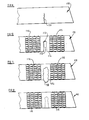
- a turbine blade is shown at 110 in which a crack 111 has occurred.
- Material from the blade 110 is removed, as shown in Figure 10, around the inner end of the crack 111, such removal creating a wide throughbore 112, or in some cases a recess, and further material is removed to create a slot 113 extending from the throughbore 112, or recess, and having a tapered configuration such that the width of the slot 113 adjacent the edge of the blade 114 is wider than the slot adjacent the throughbore 112.
- the temperature of the turbine blade 110 is raised to a first desired temperature, for example approximately 200°C.
- the temperature is raised by any suitable means providing variable and controlled heating such as electrical heating elements 115 and 116 which may extend completely around the blade 110 on both sides thereof, supply of current to which may be controlled by sensing signals derived from sensing means such as thermocouples in contact with the blade accurately to maintain its temperature at the desired value.
- the heating element 115 and control means may be similar to those described with reference to Figures 6 to 8.
- the weld metal is continued until there is a significant protrusion 118 extending beyond the edge 114 of the blade 110.
- the protrusion 118 in which a significant amount of the oxides developed during the welding operation are situated may be removed by grinding for example.
- the blade 110 is maintained at said first temperature by appropriate energisation of the electrical heating elements 115 and 116.
- excess weld material is removed, by machining for example, and the temperature of the blade is subsequently raised to a second temperature, for example 700°C to 800°C for a predetermined length of time to relieve the blade of any residual stress due to the high temperatures involved in the welding process.
- a second temperature for example 700°C to 800°C for a predetermined length of time to relieve the blade of any residual stress due to the high temperatures involved in the welding process.
- the heating elements 115 and 116 may be removed.
- the material used for the welding process may be any suitable material compatible with the material from which the blade is made, which may be for example of 12% chrome steel.
- the welding material may comprise an alloy capable of bonding satisfactorily to the parent metal of the blade but which welding material is inherently more resilient than that of the blade. Such a welding material enables some movement of the blade material to take place without excessive stress being built up in the blade since the more resilient material of the weld is capable of at least partly absorbing such movement.
- tapered slot 113 also assists in minimising stress in the blade since it permits relative movement between the two parts of the blade either side of the slot during the welding process, which movement will occur during solidification of the fused material of the weld tending to close that part of the slot 113 where welding material has not yet been applied.
- thermocouples very accurate control of the temperature of the blade both before, during and after the welding process can be maintained, which temperatures are critical both for the minimisation of build up of stress in a blade during a weld process and subsequent stress relief after the welding process.
- a suitable resilient welding material which may be sued to effect a repair is a metal sold under the Trade Mark INCONEL filler metal 82 which comprises approximately two thirds nickel, one third chrome, plus various other metallic elements in small quantites. Such a metal has been found to be very suitable for use as the weld metal in carrying out the method of the present invention.
- FIG. 13 to 15 a method of repair is illustrated in which part of a rotor 80 is illustrated and comprises a core 81, blades 82, 83, 84, 85 and 86, which blades have respective tennons 87 to 91 by means of which they are connected to a shroud 92.
- the blade 84 has a crack 93 which it is required to repair and, after removing damaged material, the blade 84 is pre-heated on the side remote from that to which the weld material is to be positioned by heating mat 94.
- the heating mat 94 extends over a short length of the blade so as to minimise thermal expanison of the blade in a direction between its ends.
- the blades 82 and 86 will be heated by heating mat 97 to a lower temperature than the blades 83 and 85 which in turn will be heated to a lowertemperature than the blade 84 which is the one to be repaired.
- the shroud 92 may also be heated by a heating mat 98.
- the reason for the pre-distortion of the blade is to compensate for the distortion that occurs when weld metal is applied from the upper side 96 of blade 84.
- the blade 84 may be gradually reduced in temperature and if required additional heating mats may be placed thereon to control the cooling of the blade and likewise the cooling of blades 82, 83, 85 and 86 may also be controlled so that none of the blades are subjected to a sudden drop in temperature.
- the method of repair of the present invention not only produces a repaired blade less likely to fail due to stress related cracking, but the heat treatment necessaryy after repair and/or the application in mechanical forces to return the blade to its correct form is eliminated or at least considerably reduced since the stress in the blade due to the application of said thermal energy is substantially reduced.
Landscapes
- Engineering & Computer Science (AREA)
- Mechanical Engineering (AREA)
- Chemical & Material Sciences (AREA)
- Physics & Mathematics (AREA)
- Thermal Sciences (AREA)
- Crystallography & Structural Chemistry (AREA)
- Materials Engineering (AREA)
- Metallurgy (AREA)
- Organic Chemistry (AREA)
- General Engineering & Computer Science (AREA)
- Turbine Rotor Nozzle Sealing (AREA)
Claims (9)
Priority Applications (1)
| Application Number | Priority Date | Filing Date | Title |
|---|---|---|---|
| AT83303585T ATE45905T1 (de) | 1982-06-23 | 1983-06-22 | Verfahren zum reparieren von turbinenschaufeln. |
Applications Claiming Priority (4)
| Application Number | Priority Date | Filing Date | Title |
|---|---|---|---|
| GB8218214 | 1982-06-23 | ||
| GB8218214 | 1982-06-23 | ||
| GB8307164 | 1983-03-15 | ||
| GB838307164A GB8307164D0 (en) | 1983-03-15 | 1983-03-15 | Repairing turbine blades |
Publications (3)
| Publication Number | Publication Date |
|---|---|
| EP0101164A2 EP0101164A2 (fr) | 1984-02-22 |
| EP0101164A3 EP0101164A3 (en) | 1985-10-09 |
| EP0101164B1 true EP0101164B1 (fr) | 1989-08-30 |
Family
ID=26283166
Family Applications (1)
| Application Number | Title | Priority Date | Filing Date |
|---|---|---|---|
| EP83303585A Expired EP0101164B1 (fr) | 1982-06-23 | 1983-06-22 | Méthode de réparation pour aubes de turbine |
Country Status (6)
| Country | Link |
|---|---|
| US (1) | US4611744A (fr) |
| EP (1) | EP0101164B1 (fr) |
| AU (1) | AU566874B2 (fr) |
| CA (1) | CA1207137A (fr) |
| DE (1) | DE3380483D1 (fr) |
| GB (1) | GB2124126B (fr) |
Families Citing this family (80)
| Publication number | Priority date | Publication date | Assignee | Title |
|---|---|---|---|---|
| GB8320836D0 (en) * | 1983-08-02 | 1983-09-01 | Refurbished Turbine Components | Securing heaters |
| DE3521664A1 (de) * | 1985-06-18 | 1986-12-18 | BBC Aktiengesellschaft Brown, Boveri & Cie., Baden, Aargau | Verfahren zur befestigung von schaufeln auf dem umfang des rotorkoerpers einer dampfturbine |
| US4726104A (en) * | 1986-11-20 | 1988-02-23 | United Technologies Corporation | Methods for weld repairing hollow, air cooled turbine blades and vanes |
| GB2198667B (en) * | 1986-12-20 | 1991-08-07 | Refurbished Turbine Components | Parts for and methods of repairing machines |
| US4842183A (en) * | 1987-11-25 | 1989-06-27 | Turbine Components Corporation | Crack repair in hot section components of superalloys |
| US4819313A (en) * | 1988-06-03 | 1989-04-11 | Westinghouse Electric Corp. | Method of salvaging stationary blades of a steam turbine |
| US5048183A (en) * | 1988-08-26 | 1991-09-17 | Solar Turbines Incorporated | Method of making and repairing turbine blades |
| GB2227191B (en) * | 1988-09-16 | 1993-03-03 | Refurbished Turbine Components | Turbine blade repair |
| GB8821812D0 (en) * | 1988-09-16 | 1988-10-19 | Refurbished Turbine Components | Turbine blade repair |
| US4919971A (en) * | 1988-09-23 | 1990-04-24 | International Business Machines Corporation | Self-induced repairing of conductor lines |
| US4893388A (en) * | 1988-12-08 | 1990-01-16 | Westinghouse Electric Corp. | Method of modifying turbine rotor discs |
| BR8900172A (pt) * | 1989-01-11 | 1990-08-14 | Jose Francisco Lopes | Processo de mecano-metalurgico para recuperacao de maquinas ou componentes de maquinas danificados por trincas,fissuras,desgastes ou amassamentos,construidos em materiais metalicos de dificil soldabilidade e formas quaisquer |
| GB2227190B (en) * | 1989-01-24 | 1992-12-16 | Refurbished Turbine Components | Turbine blade repair |
| GB8904988D0 (en) * | 1989-03-04 | 1989-04-19 | Refurbished Turbine Components | Turbine blade repair |
| GB8906929D0 (en) * | 1989-03-28 | 1989-05-10 | Refurbished Turbine Components | Method of repairing turbine blades |
| ATE167418T1 (de) * | 1989-03-28 | 1998-07-15 | Refurbished Turbine Components | Reparaturverfahren für turbinenschaufeln |
| US4994154A (en) * | 1990-02-06 | 1991-02-19 | International Business Machines Corporation | High frequency electrochemical repair of open circuits |
| US5185513A (en) * | 1990-03-22 | 1993-02-09 | Pr Partners | Heat controller and method for heat treatment of metal |
| US5060842A (en) * | 1990-04-09 | 1991-10-29 | Westinghouse Electric Corp. | Method for refurbishing nozzle block vanes of a steam turbine |
| GB9013815D0 (en) * | 1990-06-21 | 1990-08-15 | Refurbished Turbine Components | Improvements in or relating to the repair of turbine blades |
| US5106010A (en) * | 1990-09-28 | 1992-04-21 | Chromalloy Gas Turbine Corporation | Welding high-strength nickel base superalloys |
| US5193736A (en) * | 1991-03-01 | 1993-03-16 | Interturbine Corporation | Method for repairing turbine vanes |
| GB9109016D0 (en) * | 1991-04-26 | 1991-06-12 | Turbine Blading Ltd | Turbine blade repair |
| GB9210191D0 (en) * | 1992-05-12 | 1992-06-24 | Turbine Blading Ltd | Turbine blade repair |
| DE4310896C1 (de) * | 1993-04-02 | 1994-03-24 | Thyssen Industrie | Verfahren zum Herstellen von verschleißfesten Kanten an Turbinenschaufeln |
| GB9315502D0 (en) * | 1993-07-27 | 1993-09-08 | Turbine Blading Ltd | Heat treatment apparatus for turbine blades |
| US5554837A (en) * | 1993-09-03 | 1996-09-10 | Chromalloy Gas Turbine Corporation | Interactive laser welding at elevated temperatures of superalloy articles |
| GB9408156D0 (en) * | 1994-04-25 | 1994-06-15 | Turbine Blading Ltd | Turbine blade repair |
| US5783318A (en) * | 1994-06-22 | 1998-07-21 | United Technologies Corporation | Repaired nickel based superalloy |
| US5553370A (en) * | 1995-02-09 | 1996-09-10 | Pepe; John | Method for repair of steam turbine blades |
| US5873703A (en) * | 1997-01-22 | 1999-02-23 | General Electric Company | Repair of gamma titanium aluminide articles |
| US5897801A (en) * | 1997-01-22 | 1999-04-27 | General Electric Company | Welding of nickel-base superalloys having a nil-ductility range |
| US6355086B2 (en) | 1997-08-12 | 2002-03-12 | Rolls-Royce Corporation | Method and apparatus for making components by direct laser processing |
| US6210108B1 (en) * | 1999-08-16 | 2001-04-03 | General Electric Company | Method for making an article portion subject to tensile stress and stress relieved article |
| US6364971B1 (en) * | 2000-01-20 | 2002-04-02 | Electric Power Research Institute | Apparatus and method of repairing turbine blades |
| US6536110B2 (en) | 2001-04-17 | 2003-03-25 | United Technologies Corporation | Integrally bladed rotor airfoil fabrication and repair techniques |
| US6532656B1 (en) * | 2001-10-10 | 2003-03-18 | General Electric Company | Gas turbine engine compressor blade restoration method |
| EP1312437A1 (fr) * | 2001-11-19 | 2003-05-21 | ALSTOM (Switzerland) Ltd | Procédé pour réparer une fissure |
| US7146725B2 (en) * | 2003-05-06 | 2006-12-12 | Siemens Power Generation, Inc. | Repair of combustion turbine components |
| US6927361B2 (en) * | 2003-09-04 | 2005-08-09 | Thomas Joseph Kelly | Surface oxide weld penetration enhancement method and article |
| CN1883151B (zh) * | 2003-09-15 | 2010-06-16 | 英特尔公司 | 用于传递多个空间信号流的多载波发射机、多载波接收机和方法 |
| US7140106B1 (en) * | 2003-09-25 | 2006-11-28 | Reynolds Russell B | Process to restore and refurbish an engine turbo charger or exhaust part |
| US20050102835A1 (en) * | 2003-11-14 | 2005-05-19 | Trewiler Gary E. | Method for repairing gas turbine rotor blades |
| US20050274701A1 (en) * | 2004-06-10 | 2005-12-15 | United Technologies Corporation | Homogeneous welding via pre-heating for high strength superalloy joining and material deposition |
| US7484651B2 (en) | 2004-10-22 | 2009-02-03 | Electric Power Research Institute, Inc. | Method to join or repair superalloy hot section turbine components using hot isostatic processing |
| US7371988B2 (en) * | 2004-10-22 | 2008-05-13 | Electric Power Research Institute, Inc. | Methods for extending the life of alloy steel welded joints by elimination and reduction of the HAZ |
| EP1658924A1 (fr) * | 2004-11-22 | 2006-05-24 | Siemens Aktiengesellschaft | Pièce avec une rainure remplie |
| US20060196918A1 (en) * | 2005-03-04 | 2006-09-07 | Lopes Jose F | Process for recovery heavy machines or machine components |
| US20060231535A1 (en) * | 2005-04-19 | 2006-10-19 | Fuesting Timothy P | Method of welding a gamma-prime precipitate strengthened material |
| US7744709B2 (en) * | 2005-08-22 | 2010-06-29 | United Technologies Corporation | Welding repair method for full hoop structures |
| US20070158388A1 (en) * | 2006-01-06 | 2007-07-12 | Honeywell International, Inc. | Apparatus and method for welding superalloys |
| FR2901246B1 (fr) * | 2006-05-19 | 2008-06-20 | Airbus France Sas | Procede de reparation d'une zone endommagee d'un fuselage d'aeronef |
| US8011097B2 (en) * | 2006-12-04 | 2011-09-06 | General Electric Company | Method, system, and computer software code for repairing a transition section of an engine |
| US8058591B2 (en) * | 2007-03-30 | 2011-11-15 | United Technologies Corp. | Systems and methods for providing localized heat treatment of gas turbine components |
| US20110120972A1 (en) * | 2009-11-20 | 2011-05-26 | Meyer Tool, Inc. | Replacement process for fluoride ion cleaning |
| CN102451969B (zh) * | 2010-10-20 | 2013-08-14 | 上海船厂船舶有限公司 | 船用可调螺距桨的修理装置及其修理方法 |
| US9068459B2 (en) | 2012-03-05 | 2015-06-30 | General Electric Company | Turbine diaphragm airfoil, diaphragm assembly, and method of repair |
| US9260978B2 (en) | 2012-03-19 | 2016-02-16 | General Electric Company | System and method for heating a stator segment |
| US9174309B2 (en) * | 2012-07-24 | 2015-11-03 | General Electric Company | Turbine component and a process of fabricating a turbine component |
| JP6177925B2 (ja) | 2012-10-24 | 2017-08-09 | リバルディ エンジニアリング リミテッド | 複合溶接ワイヤ |
| US10428657B2 (en) | 2013-06-21 | 2019-10-01 | Pratt & Whitney Canada Corp. | Method for repairing a blade |
| US9638051B2 (en) | 2013-09-04 | 2017-05-02 | General Electric Company | Turbomachine bucket having angel wing for differently sized discouragers and related methods |
| US10440829B2 (en) | 2014-07-03 | 2019-10-08 | United Technologies Corporation | Heating circuit assembly and method of manufacture |
| US10702953B2 (en) | 2014-10-15 | 2020-07-07 | Liburdi Engineering Limited | Composite welding wire and method of manufacturing |
| WO2016071799A1 (fr) * | 2014-11-06 | 2016-05-12 | Echo-Term S.R.L. | Appareil de traitement thermique |
| US9951405B2 (en) * | 2015-02-04 | 2018-04-24 | Spirit Aerosystems, Inc. | Localized heat treating of net shape titanium parts |
| CN106563929B (zh) | 2015-10-08 | 2019-09-17 | 利宝地工程有限公司 | 修复和制造涡轮发动机部件的方法及涡轮发动机部件 |
| US10247002B2 (en) | 2016-02-03 | 2019-04-02 | General Electric Company | In situ gas turbine prevention of crack growth progression |
| US10443385B2 (en) | 2016-02-03 | 2019-10-15 | General Electric Company | In situ gas turbine prevention of crack growth progression via laser welding |
| US20170218762A1 (en) | 2016-02-03 | 2017-08-03 | General Electric Company | Situ Gas Turbine Prevention of Crack Growth Progression |
| US10544676B2 (en) | 2016-02-03 | 2020-01-28 | General Electric Company | Situ gas turbine prevention of crack growth progression |
| US10094221B2 (en) | 2016-02-03 | 2018-10-09 | General Electric Company | In situ gas turbine prevention of crack growth progression |
| US10456849B2 (en) | 2017-05-25 | 2019-10-29 | General Electric Company | Composite component having angled braze joint, coupon brazing method and related storage medium |
| US20190337102A1 (en) * | 2018-05-07 | 2019-11-07 | General Electric Company | Interlocking Stage of Airfoils |
| KR102088688B1 (ko) * | 2018-09-14 | 2020-03-13 | 한국전력공사 | 저주파 유도 가열을 이용한 로터 벤딩 교정 방법 및 이를 이용한 로터 벤딩 교정 장치 |
| JP7263806B2 (ja) * | 2019-02-06 | 2023-04-25 | 中国電力株式会社 | 鋳鋼部材の溶接方法 |
| US11969962B2 (en) * | 2020-09-25 | 2024-04-30 | General Electric Company | Method for repairing composite components and associated infiltration systems and methods |
| CN112676680A (zh) * | 2020-12-17 | 2021-04-20 | 河北星烁锯业股份有限公司 | 气体保护焊修复圆锯片裂纹的方法 |
| US11541470B2 (en) | 2021-04-02 | 2023-01-03 | General Electric Company | Methods of furnace-less brazing |
| CN115555687B (zh) * | 2022-08-15 | 2025-10-31 | 航发优材(镇江)增材制造有限公司 | 一种薄壁机匣组件氩弧焊修复变形控制方法 |
Family Cites Families (15)
| Publication number | Priority date | Publication date | Assignee | Title |
|---|---|---|---|---|
| GB371801A (en) * | 1929-10-23 | 1932-04-28 | Gen Electric | Improvements in and relating to means for protection of metal objects against corrosion |
| US2454580A (en) * | 1943-03-18 | 1948-11-23 | Gen Electric | Method of manufacturing bladed rotors |
| GB823111A (en) * | 1955-05-11 | 1959-11-04 | Gen Electric | Improvements relating to the protection against oxidation of articles of molybdenum or molybdenum base alloy |
| US3045098A (en) * | 1959-11-19 | 1962-07-17 | Thermel Inc | Electric heater |
| US3246392A (en) * | 1965-07-01 | 1966-04-19 | George A Altgelt | Method of repairing aircraft cylinder heads |
| US3535768A (en) * | 1967-09-11 | 1970-10-27 | Inland Steel Co | Method for producing welded beams |
| US3574924A (en) * | 1968-10-28 | 1971-04-13 | North American Rockwell | Solid state repair method and means |
| AT293148B (de) * | 1969-04-28 | 1971-09-27 | Boehler & Co Ag Geb | Verfahren zur Herstellung von Turbinenschaufeln |
| US3932310A (en) * | 1974-03-07 | 1976-01-13 | W. R. Grace & Co. | Reduction firing of ceramics composited with organic binders |
| US4028787A (en) * | 1975-09-15 | 1977-06-14 | Cretella Salvatore | Refurbished turbine vanes and method of refurbishment thereof |
| US4098450A (en) * | 1977-03-17 | 1978-07-04 | General Electric Company | Superalloy article cleaning and repair method |
| GB1591143A (en) * | 1978-05-17 | 1981-06-17 | Girling Ltd | Control valve assemblies |
| US4176433A (en) * | 1978-06-29 | 1979-12-04 | United Technologies Corporation | Method of remanufacturing turbine vane clusters for gas turbine engines |
| JPS56163091A (en) * | 1980-05-21 | 1981-12-15 | Hitachi Ltd | Welding repair method of low-alloy cast steel turbine casing at site |
| US4498617A (en) * | 1983-03-31 | 1985-02-12 | United Technologies Corporation | Method for reshaping a gas turbine engine combustor part |
-
1983
- 1983-06-20 US US06/505,775 patent/US4611744A/en not_active Expired - Fee Related
- 1983-06-21 GB GB08316871A patent/GB2124126B/en not_active Expired
- 1983-06-22 EP EP83303585A patent/EP0101164B1/fr not_active Expired
- 1983-06-22 DE DE8383303585T patent/DE3380483D1/de not_active Expired
- 1983-06-22 CA CA000430950A patent/CA1207137A/fr not_active Expired
- 1983-06-23 AU AU16263/83A patent/AU566874B2/en not_active Ceased
Also Published As
| Publication number | Publication date |
|---|---|
| AU566874B2 (en) | 1987-11-05 |
| CA1207137A (fr) | 1986-07-08 |
| GB2124126B (en) | 1986-04-03 |
| EP0101164A3 (en) | 1985-10-09 |
| GB8316871D0 (en) | 1983-07-27 |
| AU1626383A (en) | 1984-01-05 |
| US4611744A (en) | 1986-09-16 |
| EP0101164A2 (fr) | 1984-02-22 |
| GB2124126A (en) | 1984-02-15 |
| DE3380483D1 (en) | 1989-10-05 |
Similar Documents
| Publication | Publication Date | Title |
|---|---|---|
| EP0101164B1 (fr) | Méthode de réparation pour aubes de turbine | |
| EP0056328B1 (fr) | Réparation d'une aube | |
| EP0279058B1 (fr) | Pièces de rechange et méthode pour la réparation d'aubes de turbine | |
| US6332272B1 (en) | Method of repairing a turbine blade | |
| EP2317076B1 (fr) | Procédé pour la réparation d'un composant de turbine à gaz | |
| US7810237B2 (en) | Method for repairing and/or modifying component parts of a gas turbine | |
| EP1609948B1 (fr) | Procédé de fabrication et de réparation d' un rotor à aubage intégré | |
| US5606796A (en) | Turbine blade repair | |
| CA1253810A (fr) | Fabrication d'une roue regulatrice pour rotor d'etage haute pression d'une turbine a vapeur | |
| US4841117A (en) | Method for lengthening the blading aerofoil of turbo machinery blades | |
| JPH02277902A (ja) | タービンブレード、及びその製造・修理方法 | |
| EP0558053A1 (fr) | Méthode de réparation des aubes de turbine | |
| EP0359586B1 (fr) | Réparation d'une aube de turbine | |
| EP4611959A1 (fr) | Procédé de réparation de pale d'un rotor aubagé monobloc | |
| WO1995015240A1 (fr) | Reparation d'une aube de turbine | |
| EP0512838A1 (fr) | Pièces pour et méthodes pour la réparation des aubes de turbines | |
| US6047474A (en) | Method of manufacturing a bimetallic turbine blade and use thereof | |
| WO2004065051A1 (fr) | Remise a neuf d'une turbine | |
| Hollingworth et al. | The application of weld repair techniques to reduce costs and outage time of steam turbines | |
| Frederick et al. | Laser Weld Repair of Service Exposed IN738 and GTD111 Buckets |
Legal Events
| Date | Code | Title | Description |
|---|---|---|---|
| PUAI | Public reference made under article 153(3) epc to a published international application that has entered the european phase |
Free format text: ORIGINAL CODE: 0009012 |
|
| AK | Designated contracting states |
Designated state(s): AT BE CH DE FR IT LI LU NL SE |
|
| PUAL | Search report despatched |
Free format text: ORIGINAL CODE: 0009013 |
|
| AK | Designated contracting states |
Designated state(s): AT BE CH DE FR IT LI LU NL SE |
|
| 17P | Request for examination filed |
Effective date: 19860226 |
|
| 17Q | First examination report despatched |
Effective date: 19870224 |
|
| GRAA | (expected) grant |
Free format text: ORIGINAL CODE: 0009210 |
|
| AK | Designated contracting states |
Kind code of ref document: B1 Designated state(s): AT BE CH DE FR IT LI LU NL SE |
|
| PG25 | Lapsed in a contracting state [announced via postgrant information from national office to epo] |
Ref country code: SE Effective date: 19890830 Ref country code: AT Effective date: 19890830 |
|
| REF | Corresponds to: |
Ref document number: 45905 Country of ref document: AT Date of ref document: 19890915 Kind code of ref document: T |
|
| REF | Corresponds to: |
Ref document number: 3380483 Country of ref document: DE Date of ref document: 19891005 |
|
| ITF | It: translation for a ep patent filed | ||
| ET | Fr: translation filed | ||
| PGFP | Annual fee paid to national office [announced via postgrant information from national office to epo] |
Ref country code: SE Payment date: 19900615 Year of fee payment: 8 |
|
| PLBE | No opposition filed within time limit |
Free format text: ORIGINAL CODE: 0009261 |
|
| STAA | Information on the status of an ep patent application or granted ep patent |
Free format text: STATUS: NO OPPOSITION FILED WITHIN TIME LIMIT |
|
| 26N | No opposition filed | ||
| ITTA | It: last paid annual fee | ||
| EPTA | Lu: last paid annual fee | ||
| PGFP | Annual fee paid to national office [announced via postgrant information from national office to epo] |
Ref country code: FR Payment date: 19990610 Year of fee payment: 17 |
|
| PGFP | Annual fee paid to national office [announced via postgrant information from national office to epo] |
Ref country code: DE Payment date: 19990626 Year of fee payment: 17 |
|
| PGFP | Annual fee paid to national office [announced via postgrant information from national office to epo] |
Ref country code: NL Payment date: 19990628 Year of fee payment: 17 Ref country code: CH Payment date: 19990628 Year of fee payment: 17 |
|
| PGFP | Annual fee paid to national office [announced via postgrant information from national office to epo] |
Ref country code: LU Payment date: 19990702 Year of fee payment: 17 |
|
| PGFP | Annual fee paid to national office [announced via postgrant information from national office to epo] |
Ref country code: BE Payment date: 19990819 Year of fee payment: 17 |
|
| PG25 | Lapsed in a contracting state [announced via postgrant information from national office to epo] |
Ref country code: LU Free format text: LAPSE BECAUSE OF NON-PAYMENT OF DUE FEES Effective date: 20000622 |
|
| PG25 | Lapsed in a contracting state [announced via postgrant information from national office to epo] |
Ref country code: LI Free format text: LAPSE BECAUSE OF NON-PAYMENT OF DUE FEES Effective date: 20000630 Ref country code: CH Free format text: LAPSE BECAUSE OF NON-PAYMENT OF DUE FEES Effective date: 20000630 Ref country code: BE Free format text: LAPSE BECAUSE OF NON-PAYMENT OF DUE FEES Effective date: 20000630 |
|
| BERE | Be: lapsed |
Owner name: REFURBISHED TURBINE COMPONENTS LTD Effective date: 20000630 |
|
| PG25 | Lapsed in a contracting state [announced via postgrant information from national office to epo] |
Ref country code: NL Free format text: LAPSE BECAUSE OF NON-PAYMENT OF DUE FEES Effective date: 20010101 |
|
| REG | Reference to a national code |
Ref country code: CH Ref legal event code: PL |
|
| PG25 | Lapsed in a contracting state [announced via postgrant information from national office to epo] |
Ref country code: FR Free format text: LAPSE BECAUSE OF NON-PAYMENT OF DUE FEES Effective date: 20010228 |
|
| NLV4 | Nl: lapsed or anulled due to non-payment of the annual fee |
Effective date: 20010101 |
|
| REG | Reference to a national code |
Ref country code: FR Ref legal event code: ST |
|
| PG25 | Lapsed in a contracting state [announced via postgrant information from national office to epo] |
Ref country code: DE Free format text: LAPSE BECAUSE OF NON-PAYMENT OF DUE FEES Effective date: 20010403 |