EP0101189A2 - Zerstörungsfreie Prüfungsanordnung mit einem Flüssigkristalldetektor - Google Patents
Zerstörungsfreie Prüfungsanordnung mit einem Flüssigkristalldetektor Download PDFInfo
- Publication number
- EP0101189A2 EP0101189A2 EP83304107A EP83304107A EP0101189A2 EP 0101189 A2 EP0101189 A2 EP 0101189A2 EP 83304107 A EP83304107 A EP 83304107A EP 83304107 A EP83304107 A EP 83304107A EP 0101189 A2 EP0101189 A2 EP 0101189A2
- Authority
- EP
- European Patent Office
- Prior art keywords
- cell
- liquid crystal
- ultrasonic
- covers
- frequency
- Prior art date
- Legal status (The legal status is an assumption and is not a legal conclusion. Google has not performed a legal analysis and makes no representation as to the accuracy of the status listed.)
- Granted
Links
Images

Classifications
-
- G—PHYSICS
- G02—OPTICS
- G02F—OPTICAL DEVICES OR ARRANGEMENTS FOR THE CONTROL OF LIGHT BY MODIFICATION OF THE OPTICAL PROPERTIES OF THE MEDIA OF THE ELEMENTS INVOLVED THEREIN; NON-LINEAR OPTICS; FREQUENCY-CHANGING OF LIGHT; OPTICAL LOGIC ELEMENTS; OPTICAL ANALOGUE/DIGITAL CONVERTERS
- G02F1/00—Devices or arrangements for the control of the intensity, colour, phase, polarisation or direction of light arriving from an independent light source, e.g. switching, gating or modulating; Non-linear optics
- G02F1/01—Devices or arrangements for the control of the intensity, colour, phase, polarisation or direction of light arriving from an independent light source, e.g. switching, gating or modulating; Non-linear optics for the control of the intensity, phase, polarisation or colour
- G02F1/13—Devices or arrangements for the control of the intensity, colour, phase, polarisation or direction of light arriving from an independent light source, e.g. switching, gating or modulating; Non-linear optics for the control of the intensity, phase, polarisation or colour based on liquid crystals, e.g. single liquid crystal display cells
-
- G—PHYSICS
- G01—MEASURING; TESTING
- G01H—MEASUREMENT OF MECHANICAL VIBRATIONS OR ULTRASONIC, SONIC OR INFRASONIC WAVES
- G01H9/00—Measuring mechanical vibrations or ultrasonic, sonic or infrasonic waves by using radiation-sensitive means, e.g. optical means
- G01H9/002—Measuring mechanical vibrations or ultrasonic, sonic or infrasonic waves by using radiation-sensitive means, e.g. optical means for representing acoustic field distribution
-
- G—PHYSICS
- G01—MEASURING; TESTING
- G01N—INVESTIGATING OR ANALYSING MATERIALS BY DETERMINING THEIR CHEMICAL OR PHYSICAL PROPERTIES
- G01N29/00—Investigating or analysing materials by the use of ultrasonic, sonic or infrasonic waves; Visualisation of the interior of objects by transmitting ultrasonic or sonic waves through the object
- G01N29/04—Analysing solids
- G01N29/06—Visualisation of the interior, e.g. acoustic microscopy
- G01N29/0609—Display arrangements, e.g. colour displays
-
- G—PHYSICS
- G03—PHOTOGRAPHY; CINEMATOGRAPHY; ANALOGOUS TECHNIQUES USING WAVES OTHER THAN OPTICAL WAVES; ELECTROGRAPHY; HOLOGRAPHY
- G03H—HOLOGRAPHIC PROCESSES OR APPARATUS
- G03H3/00—Holographic processes or apparatus using ultrasonic, sonic or infrasonic waves for obtaining holograms; Processes or apparatus for obtaining an optical image from them
Definitions
- This invention relates to an apparatus and method for inspection and examination of bodies using ultrasonics, and more particularly, to an improved detector cell.
- U.S. Patent 3,766,775 to Gunkel One type of apparatus for ultrasonic non-destructive inspection is disclosed in U.S. Patent 3,766,775 to Gunkel.
- Commercial ultrasonic inspection is based upon pulse-echo technology, whereby an ultrasonic signal or pulse is directed into a body, its echoes or reflections from-the body are received and then electronically analyzed to establish an image.
- the images are then displayed using a cathode ray tube (CRT) or graphically plotted using an x-y plotter to develop what is referred to as an A-scan, B-scan or C-scan, etc.
- CTR cathode ray tube
- Such an image will take a substantial length of time to develop, due to the considerable amount of time involved in scanning the body with the ultrasonic beam, this is particularly true if the body is large.
- Computers have been used to speed this process, but at the expense of sophisticated signal processing and cost.
- the images developed require a great deal of operator interpretation and
- the equipment that is generally used in pulse-echo systems includes an ultrasonic transducer, complex signal processing equipment and complex image generating equipment. This equiment is large, does not easily lend itself to field use, and is not convenient for use in hand-held or hand-carried applications.
- the laminated structure of said copending application, Ser. No. 232,247 provides a significant advance over the prior cell structures as disclosed in the Dreyer, Kessler, et, al., Greguss and Brenden prior art patents.
- the laminated structures require careful fabrication, and while they are functionally far superior to the existing prior art technology, it is desirable to provide a cell which is less expensive to fabricate and more easily fabricated, but which still has the desired acousto-optic properties.
- one object of this invention is to disclose an improved system, and an improved liquid crystal cell for use in an acousto-optic system, for non-destructive and non-invasive examination and testing of bodies, including concealed portions of said bodies, so as to provide a real-time image of the results of such testing.
- the performance of the cell can be enhanced by aligning the liquid crystal molecules obliquely, preferably at a small angle, to the incident ultrasonic beam.
- Such alignment permits the development or formation of the equivalent of a mechanicl torque couple, that results in the liquid crystal molecule being more readily responsive, or reactant, to the ultrasonic energy, and thus more sensitive to incident, modified, ultrasonic energy that emerges from the body that is insonified.
- the cells disclosed herein are acoustically matched to the transducer frequency and surrounding sound transmitting medium, have high acoustic transmission, and are sensitive to small variations in received ultrasonic signals. Such cells are very effective to detect and display the image of a body which has been ultrasonically illuminated, or insonified.
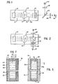
- FIG. 1 An ultrasonic inspection system which embodies the present invention is diagrammatically shown in Figs. 1 and 2.
- a sending transducer 10 directs a vectored beam 11 of ultrasonic energy through a body 12 which includes an internal defect 14.
- the ultrasonic energy 15 exiting the insonified body carries with it information as to the internal structure and that energy is directed to the liquid crystal acousto-optical cell 16.
- a real-time image of the body is formed in the cell and is seen by the viewer 18 with the use of a reflective optical system which includes a collimated light source 20, polarizer 22, half-silvered mirror 24, for both reflection and transmission of light, as indicated, and a polarizer type analyzer 26.
- the transducer 10, body 12 and cell 16 are acoustically coupled to each other, usually by water, and in Fig. 1, the coupling is shown through a transparent water bath 28.
- FIG. 2 Another system which uses a transmission optical system is shown in Fig. 2 and has elements similar to those in Fig. 1. The principal difference is the inclusion in the water bath of a sonic reflector 25, which is'optically transparent, and the deletion of the half-silvered mirror 24. It should be noted that acoustic lenses can be used, as needed, in either system to form the acoustic image of the body 12 on the cell 16.
- small (e.g., 0.2 mm) flaws 14 are located by using high frequency (e.g., 10 MHz) ultrasonic signals.
- high frequency e.g. 10 MHz
- absorption of ultrasonic energy is a function of the square of the frequency, and the use of high frequency signals can result in appreciable absorption of the ultrasonic radiation in the coupling medium, particularly where the signal path from the transducer 10 to detector cell 16 is long.
- reflective systems are used so that the ultrasonic signal path can be minimized by bringing the detector cell close to the test object.
- transmission systems having longer signal paths can be advantageously employed.
- the acoustic coupling needn't be through a bath, but may be effected through films or layers of water or silicone liquids.
- such a cell includes a liquid crystal layer 30 which is encapsulated in a chamber, or space, defined between a pair of spaced, parallel covers or substrates 32 and 34, and with the chamber completed by a peripheral seal 36.
- Protective layers prevent reaction between the liquid crystal material 30, and the substrates 32 and 34.
- the liquid crystal molecules of the liquid crystal material 30 are homeotropically aligned, which means the alignment or average direction of the molecules, is perpendicular to the adjacent sides of the substrates 32 and 34. Alignment is designated by a "director", which is an arrow with the letter "n”.
- Effective cell covers must meet several criteria. First, they must be substantially acoustically transparent. The major factors which affect transparency are substrate thickness, incident ultrasonic beam angle, and acoustic impedance of the substrate. According to traditional ultrasonic theory, a substrate is substantially transparent to ultrasonic radiation when the incident ultrasonic energy is normal or perpendicular to the substrate, and when the thickness of the substrate is a multiple of the wavelength divided by two (NX/2). However, this relationship does not hold true where the incident beam is oblique, or not normal, to the substrate. Therefore, to be useful, the covers should also exhibit acoustic transmission at various incident beam angles, which transmission is substantially equal to the transmission at normal incidence.
- the acoustic impedance of the covers should approximate that of the coupling medium, which is usually water. More specifically, the acoustic impedance of water is 1.509 x 10 6 Kg/m 2 sec., and the acoustic impedance of the substrates should be within an order of magnitude of that value. Effective substrates have been used where impedance is not greater than about 5.0 x 10 6 K g/m 2 sec. However, it must be remembered that impedance is not the sole factor governing acoustic transparency, and thus other materials may be suitable depending upon cell geometry, beam angle, etc.
- the covers must be substantially rigid so as to maintain a uniform thickness for the liquid crystal layer.
- the ultrasonically active area of each cover i.e. the portions of the covers exposed to the ultrasonic beam and which overlie the liquid crystal material
- the covers should not chemically react with the liquid crystal material, as such will degrade image quality.
- at least one cover must be optically transparent so that the viewer may see images produced by the liquid crystal.
- acoustic transmission through each cell cover as great as possible and transmission of greater than about 85% has been found to be acceptable.
- transmission should be available at angles between about +40° from normal. This assures a wide band of the cell sensitivity by minimizing energy losses in the covers and maximizing transmission of incident ultrasonic energy to the liquid crystal.
- the laminated covers as described in copending application, Serial No. 232,247 meet the criteria.
- Other materials which I discovered meet the stated performance criteria includes: multi-ply glass laminates; graphite fiber/epoxy composites; and certain polymeric materials.
- the graphite fiber/epoxy composites are fabricated by standard techniques in which unidirectional graphite fiber/epoxy sheets are overlaid to give any desired orientation for the composite and then fused and cured to form the composite.
- Composites which have transverse fiber orientations, angular orientations and parallel orientations have been prepared.
- Stretched film or membrane covers can also meet the criteria, but may have deficiencies, as far as the frames or fixtures required to maintain rigidity in large sizes.
- the acoustic transmission characteristics, of several suitable cover materials, as a function of the incidence angle of the ultrasonic vector, or beam, at various frequencies have been determined.
- the importance of the incidence angle is related to the problems in assuring normal or perpendicular alignment of a cell and transducer in actual use. Perfect normal alignment is very difficult to obtain and maintain.
- Covers, or substrates, which are not angularly sensitive are the most useful. It has been determined that for a given thickness of a cover, acoustic transmission varies principally with acoustic frequency, beam angle, nature of the cover material, and cover construction.
- Tests have been run on three-ply glass laminates as cell covers. Each ply was .0085 inch thick and the plies were adhesively bonded to each other. The tests were run at frequencies between 2.5 and 6.0 MHz and at incident beam angles between -60 and +60 degrees from normal which is designated as zero (0°). The tests indicate that at frequencies between 4.5 and 6.0 MHz there are irregular responses, which indicate that these three ply glass laminates may be difficult to use in that frequency range. On the other hand, the tests at 3.5 and 4.0 MHz show three broad plateaus, namely between: about -40 and -15 degrees; about -10 and +10 degrees; and about +15 and +40 degrees. Transmission in these ranges was greater than 85%. These experimental results suggest good wide operating ranges.
- the acoustic impedance of glass is 11.4 x 10⁶ K g/m 2 sec.
- a typical laminated glass cell construction 60 is shown in Fig. 7 where the cover 62 includes three glass plies 64, 66 and 68 which are bonded by the two adhesive plies 70 and 72. The other cover is designated as 74, the spacer as 76 and the liquid crystal material as 78.
- this material is optically transparent. In the thickness used, the material is also substantially rigid for the intended purposes.
- the acoustic impedance of the material is 3.0 x 10 6 K g/m 2 sec. Thus from almost every.aspect, this polyester provides an excellent cover material.
- Another material which has been found to be useful as a cell cover is a laminate constructed of plies of graphite fiber/epoxy composite.
- the plies are parallel to each other, but the fibers may be at right angles to each other.
- These laminates are: substantially rigid for the intended purposes, chemically compatible with liquid crystal materials, and exhibit good acoustic transmission (i.e., greater than 85%), but are optically opaque.
- Both three-layer and four-layer composites were tested at frequencies between 2.5 and 6.0 MHz, and the composites exhibited similar properties. The average value of the acoustic impedance of this material across the fibers is estimated to be 1.5 x 10 6 Kg/m sec.
- a composite substrate can be oriented so that the fibers are in the transverse or parallel orientation with respect to the plane of the transducer.
- a two-layer graphite/epoxy cell cover wherein the layers had the fibers therein arranged parallel, was found to be the most effective cell cover tested.
- the graphite fiber/epoxy composite also has the desired rigidity and chemical stability.
- the particular layers had about 40% graphite fibers and about 60% epoxy. It is believed that the fiber content of the layers can be varied over a very wide range and still provide an effective substrate.
- the graphite fiber/epoxy material is well known for use in aerospace industry. It is available in uncured form on rolls of a sheet substrate. Sources include Hercules Corp. of Magna, Utah or NARMCO Corp. of Costa Mesa, Calif.
- one of the cell covers, or substrates could be opaque and could be fabricated from a parallel fiber, graphite fiber/epoxy composite, and the other cell cover could be optically transparent and fabricated from an appropriate polyester, or be of glass laminate construction.
- polyester and graphite/epoxy substrates are easy to fabricate and make into cells.
- the glass laminate * is somewhat more difficult to fabricate, but has also been successfully made into cells.
- Monolithic glass covers have also been tested but exhibit irregular ultrasonic transmission characteristics which make them usable only under very carefully controlled conditions.
- Another cell cover can be prepared from a stretched polyester membrane. However, those membranes require complex frames to maintain their rigidity and tend to relax.
- Rigidity of the cell cover is important, to assure providing a cell size-to-image size ratio that minimizes edge effects of the cell.
- the cell size must be sufficiently greater than the image size so as to preclude the image approaching the cell edges, which could cause some distortion in the image produced.
- the two spaced covers of the cell are selected to be substantially equally acoustically transparent, over their entire operative areas, so as to minimize internal reflection within the liquid crystal layer of the cell, and this is achieved, in one manner herein, by making operative portions of the covers substantially identical in thickness, material, and orientation relative to the liquid crystal layer of the cell.
- a protective barrier layer such as a silicone oxide layer, or film, such as 32a and 34a, or 35, at the cover/liquid crystal interfaces.
- barrier layers can be vacuum deposited, or sputtered, onto the substrates.
- Such a barrier layer has been successfully used with each of the substrate materials disclosed herein.
- These barrier layers have a thickness of about 200 Angstroms, which is much much less than ⁇ /4, where A is the wavelength of the ultrasonic energy.
- appropriate cell covers can be selected to maximize acoustic transmission over a wide range of sonic incidence angles and the appropriate optically opaque or transparent covers selected.
- the liquid crystal material positioned between the substrate covers is the sensor which produces therein the ultrasonic image.
- the image is produced by the interaction of the ultrasonic energy with the liquid crystal material to produce birefringence.
- This effect is referred to as the acousto-optic effect, or the field birefringent effect.
- This effect is usually viewed using the collimated light source and polarizer/analyzer combination whose orientation is adjusted for best viewing conditions.
- the cells are constructed so that the maximum amount of ultrasonic energy is transmitted through both cell covers so that the ultrasonic energy absorbed within the cell is minimized.
- the liquid crystal material is selected or manipulated to maximize its sensitivity to variations in the ultrasonic signal and to maximize its response to the ultrasonic frequency used.
- a liquid crystal material includes elongated molecules which are generally aligned with respect to each other. Such materials are anisotropic (i.e., their properties are not the same in every direction). This property is demonstrated by the optical birefringence which permits viewing of the image.
- the particular liquid crystal material is selected on the bases of: its sensitivity to the ultrasonic energy and the frequency used, its ability to be aligned relative to the cell covers, and to be moved from that alignment and returned to the alignment.
- Nematic liquid crystal materials are preferably used, as they can be selectively aligned with respect to the cell cover.
- the liquid crystal layer of the cell may include a single pure nematic material or a mixture of nematics.
- K-15 One nematic crystal material that has been successfully used is commercially known as K-15, has the chemical name 4-cyano-4'n-pentylphenyl and the following chemical structure: K-15 can be purchased from BDH Co., located in Poole, Dorset, England. Other nematics are commercially available. The nematics can be aligned normal to the cell substrates and have sufficient sensitivity. "Director” is a term used to designate the average or bulk alignment of the liquid crystal molecules. The "director” shown in Figs. 3 and 4 of the drawings, includes the letter “n” and an arrow which points in the alignment direction. When the director is normal to the cell covers, the alignment is referred to as homeotropic.
- Twisted nematics are commonly used in electro-optic liquid crystal displays, for example, in digital watches. Twisted nematics are nematics to which approximately .03% by weight cholesteric liquid crystal material has been added, to provide a helical or twisted structure for the liquid crystal layer.
- a nematic liquid crystal is a material whose phase-changes with temperature from a crystalline phase to a nematic phase and then to an isotropic phase. It has been found that the sensitivity of nematics to ultrasonic energy is greatest at temperatures close to but below the nematic/isotropic (N/I) phase transformation temperature. It has also been found that the response time of a cell (i.e., time to respond to the presence or absence of an ultrasonic signal) is improved, and appears to be most desirable, just below the N/I phase transformation temperature. Thus, in selecting a nematic liquid crystal, it is desirable to use a nematic liquid crystal having a N/I phase transformation temperature just above the operating temperature for the detector cell.
- the N/I temperature is a physical property of each nematic, but the N/I temperature of a liquid crystal material mixture can be adjusted by mixing nematics having different N/I temperatures.
- the N/I transition is at about 35.3°C.
- each particular liquid crystal material exhibits a maximum, or optimum,change in optical characteristics at one particular exciting frequency with the response being less at other frequencies.
- K-15 appears to be very responsive to ultrasonic energy and to be more responsive at 3.5 MHz than at any other frequency.
- Another consideration in selecting a liquid crystal is to employ a material which has a broad "non-streaming" band or region.
- the ultrasonic amplitude to be used must be maintained below the streaming point for the particular liquid crystal material.
- streaming can be minimized by pulsing the ultrasonic beam.
- the ultrasonic transducer is cycled between operating and non-operating modes.
- energy is directed toward the cell for a very short period of time at which point the transducer is turned off and then turned back on again for a short period of time.
- An optical analogy is a stroboscopic light. It has been discovered that it is desirable to pulse the ultrasonic energy so as to reduce the amount of energy absorbed by the liquid crystal layer, and to thereby minimize the problem of streaming.
- electric field enhancement may be used.
- an electric field is applied to the cell in relation to the on and off modes of the ultrasonic beam. It has been found that sensitivity can be increased by applying an electric field of a first frequency, f l , while the ultrasonic beam is on.
- the frequency is selected to orient the liquid crystals in a direction that is not normal to the cell covers, and thus aids the acoustic field in production of the image. This also aids in reducing the time period required to effect image forming in the detector cell, known as rise time.
- the cell can be restored to its original condition by removing the first frequency field and applying a second electric field of a different frequency, f 2 , when the ultrasonic beam is switched off.
- the second frequency is selected to restore the liquid crystal molecules to a position normal to the cell covers.
- the sequencing of applying these frequency fields is shown in Fig. 5, as related to the ultrasonic field.
- a 5 MHz ultrasonic signal can be pulsed for 50-100 microsecond duration with a few millisecond delay.
- the first frequency could be 5 KHz and the second 20 KHz.
- Nematic liquid crystal materials usually exhibit a different dielectric constant in a direction parallel to the molecule's longitudinal axis than a direction transverse to the molecule's longitudinal axis.
- the dielectric constant, E in the parallel direction is represented by en
- the subscript denoting "parallel” and in the transverse direction is represented by ⁇ the subscript denoting "perpendicular”
- the'differences may be represented as follows:
- liquid crystal materials in which the difference in dielectric constant changes from + to - with frequency. These are referred to as two-frequency materials, and exhibit the characteristic that below a particular frequency, ⁇ will be greater than zero while above that frequency, ⁇ will be less than zero. This property permits the use of a liquid crystal material such that the alignment of its director is controllable through selection of the frequency of electric field that is applied to the liquid crystal layer of the detecting cell. Two-frequency materials are particularly suitable for use in pulsed ultrasonic applications, to selectively produce parallel or perpendicular alignment.
- FIG. 4 A system for electric field enhancement is shown in Fig. 4, which illustrates diagrammatically the relationship of the elements of the system and details of the improved cell.
- Fig. 4 shows a light source 44 preferably collimated whose illumination is directed through a polarizer 46 toward the cell 16.
- Reference 52 represents the ultrasonic energy, or radiation, vectored in the direction of the arrows perpendicularly toward the surface of the cell, said cell being shown greatly enlarged in Fig. 4.
- both the light source and ultrasonic energy are directed toward the cell from one side thereof.
- Reference “n” is the director, and it is shown parallel to, or aligned with the viewing axis, but it is oblique to the vector direction of the ultrasonic energy 52 and also to the outer surface of the covers 32 and 34 of the cell.
- the cell includes two spaced, parallel, substrates, 32 and 34; the liquid crystal material 30, such as K-15; the peripheral sealing spacer 36; and thin silicone oxide barrier layers 35 adjacent the liquid crystal 30, as shown.
- the barrier layers 35 and their respective adjacent substrates 32 and 34 there are provided thin film, transparent, electrodes, 38 and 40 whose thickness is much much less than A/4. These electrodes are substantially co-extensive in area size with the substrates.
- the electrodes are electrically connected to a generator 42, which supplies low frequency AC to the electrodes.
- the low frequency AC applied at a low voltage (i.e. up to 10 volts r.m.s.) to electrodes 38 and 40 prevents ion migration and maintains the desired alignment of liquid crystal molecules.
- the substrates 32 and 34 each with its adjacent electrode and silicone oxide barrier layer applied thereto, has the exposed surface of the barrier layer rubbed with fine tissue paper or other material, unidirectionally for an ultimate purpose of providing a desired alignment effect on the molecules of the liquid crystal material 30, namely causing the molecules of the liquid crystal material to become oriented in a generally uniform attitude, which can, with application of an electric field, be moved between a homeotropic alignment that is substantially normal to the cell covers and an inclined alignment, such as parallel to a director, such as shown by "n" in Fig. 4.
- the rubbed surfaces are coated with a surfactant, such as lecithin, which is in contact with the liquid crystal material 30 in the assembled cell.
- lecithin or other similar surfactant chemicals it is known to apply lecithin or other similar surfactant chemicals to surfaces in contact with liquid crystals, in order to initially align the liquid crystal molecules.
- the lecithin molecules are believed to align the liquid crystal molecules perpendicular to contact surfaces.
- lecithin or another surfactant could be used herein, the AC electric field is principally relied on for alignment.
- guest/host which can be used.
- Guest/ host which combines a nematic crystal as "host” and a dichroic dye as the "guest" employs a dye to make the image visible.
- the liquid crystal layer is preferably approximately .020 inches thick, the spacing between the two barrier layers 35, and should not be less than .015 inches thick. The reason is that in this thickness the surface effects of the substrates are minimized and the bulk of the liquid crystal can respond to the ultrasonic energy. While these thicknesses are preferred, it must be recognized that the ultrasonic frequency and cell cover construction will affect the choice of thickness of the liquid crystal layer and may even permit use of thinner layers.
- the structure of the cell shown in Fig. 4 is preferred for increasing the sensitivity of the cell by aligning the liquid crystal molecules obliquely to the entering ultrasonic beam 52.
- the director "n" of the molecules should be inclined at a small angle (e.g., less than 10°) to the covers; or if the beam 52 is inclined at a small angle to the normal of the cell cover, then the director "n" of the molecules should not be parallel to the vector of the ultrasonic beam, but should be inclined to the beam and may be normal, or homeotropically aligned to the substrates.
- the optical view axis should be substantially parallel to the molecular alignment as indicated by the director "n".
- the oblique liquid crystal director/ultrasonic beam alignment increases sensitivity, since the vector of the force of the ultrasonic beam is not directly aligned with the ends of the liquid crystal molecules in an axial direction, but rather is directed to strike the side of the molecule, to produce, or induce, a stress or strain effect, such as a bending, a tipping, or rotary motion of the liquid crystal molecules that will produce the desired birefringence.
- This effect, or action can be also thought of as a torque couple, as that term is used in mechanics.
- the substrates are first unidirectionally rubbed or chemically treated to produce an initial alignment. See, F. J. Kahn, et al., Journal of Applied Physics, 1972.
- a liquid crystal is selected in which ⁇ 0, and a slight electric field is applied by generator 42 to produce the oblique alignment of the liquid crystal relative to the plane of the substrate.
- the transmission optical system is shown preferably aligned with the director "n" and includes the light source 44, polarizer 46, analyzer 48 and viewer 50.
- the ultrasonic energy 52 from the test object is shown at normal incidence to the cell. Normal incidence is preferred, as the substrate must follow the ⁇ /2 rule, but non-normal or oblique incidence could also be used.
- a suitable liquid crystal material can be selected which has the maximum sensitivity for that frequency or band. Then, if necessary, electric field enhancement and pulsed ultrasonic signals can be used to further enhance the image, sensitivity, resolution and response time.
- each cell will vary depending upon the specific application or use to which the cell is placed.
- both cell covers must be acoustically and optically transparent. Both covers could be glass laminates or polyesters or one cover could be glass laminate and the other cover a polyester.
- the cell cover on the object side will be acoustically transparent and optically opaque, with an optical mirror surface applied to the cover surface which interfaces with the liquid crystal.
- a cover on the object side could be an epoxy/graphite composite.
- the other cover should be optically transparent, such as glass laminate or polyester.
- a visco elastic flaw in the form of a square patch, sized 3/8" x 3/8" x .001 inch, embedded in a 16-ply epoxy/graphite composite that was 1/8 inch thick, was successfully observed using a liquid crystal cell.
- the material examined was of the type which is now used in aerospace applications.
- Fig. 6 is a representation of the light illuminated liquid crystal cell 16, which exhibits thereon the acoustical image of an insonified test object and the flaw embedded in said test object.
- the generally circular area 100 illustrates the insonified field image that appears on cell 16, and cross-hatched square 102, located centrally of the insonified field image 100, represents a typical appearance of a detected flaw, or defect, embedded in the graphite/epoxy material being examined.
- the ultrasonic generators or transducers used herein are of the conventional piezoelectric type which when electrically excited produce pressure waves in a liquid medium. As is known, it is desirable to work with a uniform beam of the type which is present at the near field/far field transition.
- the physical location of the near field/far field transition is governed by the ratio of the square of the radius, A, of the transducer face divided by the ultrasonic wavelength, namely A 2 / J ⁇ . In some situations the distance to the transition is so long as to be impractical.
- A the radius of the radius
- J ⁇ the ultrasonic wavelength
- the transducers which have been used in this system preferably generate frequencies in the range of 1 - 10 MHz.
- a particular frequency within that range is selected, the frequency depending upon the specific application or use for the system. It has been found that the frequency range of 3 - 6 MHz may be the most practical. However, it is anticipated that frequencies outside the range of 1 - 10 MHz may be used, again depending upon the particular application.
- Typical transducers which can be used are available from Krautkramer & Branson, or Panametrics in a 1 inch diameter and at frequencies of 1, 3.5, and 5 MHz.
- the cells and systems disclosed herein have been tested for use in industrial settings. However, these cells and systems are also suitable for use in medical imaging.
- the effectiveness of the ultrasonic inspection system is related to a combination of factors. These factors include the frequency of the ultrasonic signal, the intensity of the ultrasonic signal, the acoustic matching of the detector cell to the surrounding medium, the acoustic impedance of the cell covers, and the sensitivity of the liquid crystal material to the ultrasonic signal.
- the particular application for which the system is to be used will dictate the frequency of the ultrasonic signal, which in turn will suggest the construction and materials for the detector cell substrates as well as the particular liquid crystal material to be used.
- the problem of image enhancement will depend upon the application since in some situations the image quality without electric field enhancement will be satisfactory, whereas in other situations, it will not.
- a photographic system can record the image on the cell.
- a video camera and transmission system can be used to capture the image on the cell.
Landscapes
- Physics & Mathematics (AREA)
- General Physics & Mathematics (AREA)
- Chemical & Material Sciences (AREA)
- Nonlinear Science (AREA)
- Pathology (AREA)
- Crystallography & Structural Chemistry (AREA)
- Analytical Chemistry (AREA)
- Biochemistry (AREA)
- General Health & Medical Sciences (AREA)
- Immunology (AREA)
- Health & Medical Sciences (AREA)
- Life Sciences & Earth Sciences (AREA)
- Acoustics & Sound (AREA)
- Optics & Photonics (AREA)
- Engineering & Computer Science (AREA)
- Radar, Positioning & Navigation (AREA)
- Remote Sensing (AREA)
- Liquid Crystal (AREA)
- Investigating Or Analyzing Materials By The Use Of Ultrasonic Waves (AREA)
- Investigating Or Analyzing Materials By The Use Of Electric Means (AREA)
Priority Applications (1)
| Application Number | Priority Date | Filing Date | Title |
|---|---|---|---|
| AT83304107T ATE29782T1 (de) | 1982-07-20 | 1983-07-15 | Zerstoerungsfreie pruefungsanordnung mit einem fluessigkristalldetektor. |
Applications Claiming Priority (2)
| Application Number | Priority Date | Filing Date | Title |
|---|---|---|---|
| US06/399,997 US4506550A (en) | 1981-02-06 | 1982-07-20 | Non-destructive testing system employing a liquid crystal detector cell |
| US399997 | 1989-08-29 |
Publications (3)
| Publication Number | Publication Date |
|---|---|
| EP0101189A2 true EP0101189A2 (de) | 1984-02-22 |
| EP0101189A3 EP0101189A3 (en) | 1984-10-17 |
| EP0101189B1 EP0101189B1 (de) | 1987-09-16 |
Family
ID=23581799
Family Applications (1)
| Application Number | Title | Priority Date | Filing Date |
|---|---|---|---|
| EP83304107A Expired EP0101189B1 (de) | 1982-07-20 | 1983-07-15 | Zerstörungsfreie Prüfungsanordnung mit einem Flüssigkristalldetektor |
Country Status (10)
| Country | Link |
|---|---|
| US (1) | US4506550A (de) |
| EP (1) | EP0101189B1 (de) |
| JP (1) | JPS5972057A (de) |
| AT (1) | ATE29782T1 (de) |
| AU (1) | AU567880B2 (de) |
| CA (1) | CA1212447A (de) |
| DE (1) | DE3373704D1 (de) |
| IL (1) | IL69223A (de) |
| MX (1) | MX153563A (de) |
| ZA (1) | ZA835206B (de) |
Cited By (5)
| Publication number | Priority date | Publication date | Assignee | Title |
|---|---|---|---|---|
| EP0133007A3 (en) * | 1983-07-25 | 1985-11-06 | Raj Technology Partnership | Movable ultrasonic transducer array |
| EP0147180A3 (de) * | 1983-12-27 | 1986-12-30 | Raj Technology Partnership | Ultraschalldetektionszelle und Anordnung |
| EP0219187A1 (de) * | 1985-09-13 | 1987-04-22 | Raj Technology, Inc. | Nichtkohärente Frequenzquelle und Sektorabtasteinrichtung für Ultraschallabbildungssystem mit Flüssigkristall-Detektorzelle |
| EP0269429A3 (de) * | 1986-11-26 | 1989-08-02 | Raj Technology, Inc. | Akustische Abbildungsanordnung und Flüssigkristallzelle dafür |
| GB2586534A (en) * | 2019-04-30 | 2021-02-24 | Merck Patent Gmbh | Acousto-optical device |
Families Citing this family (13)
| Publication number | Priority date | Publication date | Assignee | Title |
|---|---|---|---|---|
| US4679436A (en) * | 1986-08-05 | 1987-07-14 | Raj Technology, Inc. | Reciprocating method and apparatus for producing uniform ultrasonic field for use in liquid crystal based acoustical imaging |
| US5311137A (en) * | 1989-10-27 | 1994-05-10 | Hughes Aircraft Company | Liquid crystal electric field tester for circuit boards |
| JPH07113533B2 (ja) * | 1990-11-30 | 1995-12-06 | 浜松ホトニクス株式会社 | 光学的変形量測定装置 |
| DE69225738T2 (de) * | 1991-03-27 | 1998-10-01 | Technology Co Ag | Flüssigkristallanzeigeelement und Projektionsanordnung unter Verwendung desselben |
| US5732706A (en) * | 1996-03-22 | 1998-03-31 | Lockheed Martin Ir Imaging Systems, Inc. | Ultrasonic array with attenuating electrical interconnects |
| WO1999057528A1 (en) | 1998-05-02 | 1999-11-11 | Focal, Inc. | Light source power tester |
| US6049411A (en) * | 1998-10-14 | 2000-04-11 | Santec Systems Inc | Optical imager for birefringent detector acoustic imaging systems |
| US6552841B1 (en) * | 2000-01-07 | 2003-04-22 | Imperium Advanced Ultrasonic Imaging | Ultrasonic imager |
| US6321023B1 (en) | 2000-06-20 | 2001-11-20 | Honghui Wang | Serial imager for birefringent detector acoustic imaging systems |
| US8063540B2 (en) * | 2004-03-08 | 2011-11-22 | Emantec As | High frequency ultrasound transducers based on ceramic films |
| TWI350414B (en) * | 2007-04-20 | 2011-10-11 | Chimei Innolux Corp | Alignment device and alignment method |
| GB0903383D0 (en) * | 2009-02-27 | 2009-04-08 | Syngenta Ltd | Sensor |
| US9671277B2 (en) * | 2015-01-22 | 2017-06-06 | Jaswinder Singh Sandhu | Light imaging system for an acoustic imaging system |
Family Cites Families (5)
| Publication number | Priority date | Publication date | Assignee | Title |
|---|---|---|---|---|
| US3707323A (en) * | 1970-11-06 | 1972-12-26 | Zenith Radio Corp | Liquid crystal devices and systems for ultrasonic imaging |
| US3831434A (en) * | 1972-03-23 | 1974-08-27 | Vari Light Corp | Methods and apparatus for image display of sound waves and utilizations thereof |
| US3991606A (en) * | 1974-11-08 | 1976-11-16 | Minnesota Mining And Manufacturing Company | Apparatus and method for converting mechanical wave energy to optical energy |
| CA1112750A (fr) * | 1978-10-13 | 1981-11-17 | Jean-Luc Dion | Cellule acousto-optique a cristal liquide |
| US4492107A (en) * | 1982-03-22 | 1985-01-08 | Raj Technology Partnership | Acoustic power meter |
-
1982
- 1982-07-20 US US06/399,997 patent/US4506550A/en not_active Expired - Fee Related
-
1983
- 1983-07-14 IL IL69223A patent/IL69223A/xx unknown
- 1983-07-15 EP EP83304107A patent/EP0101189B1/de not_active Expired
- 1983-07-15 DE DE8383304107T patent/DE3373704D1/de not_active Expired
- 1983-07-15 AT AT83304107T patent/ATE29782T1/de active
- 1983-07-18 JP JP58130735A patent/JPS5972057A/ja active Pending
- 1983-07-18 ZA ZA835206A patent/ZA835206B/xx unknown
- 1983-07-18 CA CA000432635A patent/CA1212447A/en not_active Expired
- 1983-07-18 AU AU16920/83A patent/AU567880B2/en not_active Ceased
- 1983-07-18 MX MX198074A patent/MX153563A/es unknown
Cited By (6)
| Publication number | Priority date | Publication date | Assignee | Title |
|---|---|---|---|---|
| EP0133007A3 (en) * | 1983-07-25 | 1985-11-06 | Raj Technology Partnership | Movable ultrasonic transducer array |
| EP0147180A3 (de) * | 1983-12-27 | 1986-12-30 | Raj Technology Partnership | Ultraschalldetektionszelle und Anordnung |
| EP0219187A1 (de) * | 1985-09-13 | 1987-04-22 | Raj Technology, Inc. | Nichtkohärente Frequenzquelle und Sektorabtasteinrichtung für Ultraschallabbildungssystem mit Flüssigkristall-Detektorzelle |
| EP0269429A3 (de) * | 1986-11-26 | 1989-08-02 | Raj Technology, Inc. | Akustische Abbildungsanordnung und Flüssigkristallzelle dafür |
| GB2586534A (en) * | 2019-04-30 | 2021-02-24 | Merck Patent Gmbh | Acousto-optical device |
| GB2586534B (en) * | 2019-04-30 | 2023-05-10 | Merck Patent Gmbh | Acousto-optical device |
Also Published As
| Publication number | Publication date |
|---|---|
| ATE29782T1 (de) | 1987-10-15 |
| MX153563A (es) | 1986-11-14 |
| AU1692083A (en) | 1984-01-26 |
| IL69223A0 (en) | 1983-11-30 |
| AU567880B2 (en) | 1987-12-10 |
| EP0101189A3 (en) | 1984-10-17 |
| JPS5972057A (ja) | 1984-04-23 |
| EP0101189B1 (de) | 1987-09-16 |
| DE3373704D1 (en) | 1987-10-22 |
| IL69223A (en) | 1986-09-30 |
| US4506550A (en) | 1985-03-26 |
| CA1212447A (en) | 1986-10-07 |
| ZA835206B (en) | 1984-04-25 |
Similar Documents
| Publication | Publication Date | Title |
|---|---|---|
| US4506550A (en) | Non-destructive testing system employing a liquid crystal detector cell | |
| US4338821A (en) | Liquid crystal cell for acoustical imaging | |
| Urbach et al. | Alignment of nematics and smectics on evaporated films | |
| Johnson et al. | Nonlinear generation of elastic waves in crystalline rock | |
| US4012951A (en) | Acoustic examination methods and apparatus | |
| US4379408A (en) | Liquid crystal technique for examining internal structures | |
| US4651567A (en) | Non-coherent frequency source and sector scanning apparatus for ultrasonic imaging system using a liquid crystal detector cell | |
| US4905202A (en) | Detection panel and method for acoustic holography | |
| Rollins Jr | Ultrasonic Examination of Liquid‐Solid Boundaries Using a Right‐Angle Reflector Technique | |
| US4393712A (en) | Portable liquid crystal testing device | |
| US3991606A (en) | Apparatus and method for converting mechanical wave energy to optical energy | |
| US4652086A (en) | Ultrasonic detector cell and system | |
| JPH0330105B2 (de) | ||
| Hallermeier et al. | Simple technique for exciting and probing elastic surface waves | |
| JPS63212917A (ja) | 音響作像液晶セルの構造 | |
| CA1179763A (en) | Liquid crystal technique for examining internal structures | |
| Nagai et al. | Ultrasonic imaging utilizing a nematic liquid crystal | |
| Kittinger et al. | Improvement of echo shape in low impedance materials | |
| Lim et al. | Dynamic characteristics of disbonds in honeycomb structures | |
| EP0113941A1 (de) | Akusto-optische Flüssigkristalldetektorzelle | |
| Archer-Hall et al. | The photoelastic visualization of ultrasonic waves in liquids | |
| Holt et al. | Wavevector reversed ultrasound as a new tool in investigations of phase transitions | |
| JPH076957B2 (ja) | 超音波顕微鏡の探触子 | |
| JPH09243620A (ja) | センサ | |
| Hayes | Angular dependence of the acousto-optical effect |
Legal Events
| Date | Code | Title | Description |
|---|---|---|---|
| PUAI | Public reference made under article 153(3) epc to a published international application that has entered the european phase |
Free format text: ORIGINAL CODE: 0009012 |
|
| AK | Designated contracting states |
Designated state(s): AT BE CH DE FR GB IT LI LU NL SE |
|
| PUAL | Search report despatched |
Free format text: ORIGINAL CODE: 0009013 |
|
| AK | Designated contracting states |
Designated state(s): AT BE CH DE FR GB IT LI LU NL SE |
|
| 17P | Request for examination filed |
Effective date: 19850404 |
|
| 17Q | First examination report despatched |
Effective date: 19860515 |
|
| GRAA | (expected) grant |
Free format text: ORIGINAL CODE: 0009210 |
|
| AK | Designated contracting states |
Kind code of ref document: B1 Designated state(s): AT BE CH DE FR GB IT LI LU NL SE |
|
| PG25 | Lapsed in a contracting state [announced via postgrant information from national office to epo] |
Ref country code: LI Effective date: 19870916 Ref country code: CH Effective date: 19870916 Ref country code: BE Effective date: 19870916 Ref country code: AT Effective date: 19870916 |
|
| REF | Corresponds to: |
Ref document number: 29782 Country of ref document: AT Date of ref document: 19871015 Kind code of ref document: T |
|
| ITF | It: translation for a ep patent filed | ||
| PG25 | Lapsed in a contracting state [announced via postgrant information from national office to epo] |
Ref country code: SE Effective date: 19870930 |
|
| ET | Fr: translation filed | ||
| REF | Corresponds to: |
Ref document number: 3373704 Country of ref document: DE Date of ref document: 19871022 |
|
| REG | Reference to a national code |
Ref country code: CH Ref legal event code: PL |
|
| R20 | Corrections of a patent specification |
Effective date: 19871203 |
|
| PLBE | No opposition filed within time limit |
Free format text: ORIGINAL CODE: 0009261 |
|
| STAA | Information on the status of an ep patent application or granted ep patent |
Free format text: STATUS: NO OPPOSITION FILED WITHIN TIME LIMIT |
|
| PG25 | Lapsed in a contracting state [announced via postgrant information from national office to epo] |
Ref country code: LU Free format text: LAPSE BECAUSE OF NON-PAYMENT OF DUE FEES Effective date: 19880731 |
|
| PGFP | Annual fee paid to national office [announced via postgrant information from national office to epo] |
Ref country code: DE Payment date: 19880804 Year of fee payment: 6 |
|
| 26N | No opposition filed | ||
| PG25 | Lapsed in a contracting state [announced via postgrant information from national office to epo] |
Ref country code: GB Effective date: 19890715 |
|
| PG25 | Lapsed in a contracting state [announced via postgrant information from national office to epo] |
Ref country code: NL Effective date: 19900201 |
|
| NLV4 | Nl: lapsed or anulled due to non-payment of the annual fee | ||
| PG25 | Lapsed in a contracting state [announced via postgrant information from national office to epo] |
Ref country code: FR Free format text: LAPSE BECAUSE OF NON-PAYMENT OF DUE FEES Effective date: 19900330 |
|
| PG25 | Lapsed in a contracting state [announced via postgrant information from national office to epo] |
Ref country code: DE Effective date: 19900403 |
|
| GBPC | Gb: european patent ceased through non-payment of renewal fee | ||
| REG | Reference to a national code |
Ref country code: FR Ref legal event code: ST |