EP0101192A2 - Test module for a clinical analyzer - Google Patents
Test module for a clinical analyzer Download PDFInfo
- Publication number
- EP0101192A2 EP0101192A2 EP83304116A EP83304116A EP0101192A2 EP 0101192 A2 EP0101192 A2 EP 0101192A2 EP 83304116 A EP83304116 A EP 83304116A EP 83304116 A EP83304116 A EP 83304116A EP 0101192 A2 EP0101192 A2 EP 0101192A2
- Authority
- EP
- European Patent Office
- Prior art keywords
- test module
- serum
- cup
- dilution
- valve
- Prior art date
- Legal status (The legal status is an assumption and is not a legal conclusion. Google has not performed a legal analysis and makes no representation as to the accuracy of the status listed.)
- Granted
Links
- 238000012360 testing method Methods 0.000 title claims abstract description 73
- 239000000523 sample Substances 0.000 claims abstract description 73
- 210000002966 serum Anatomy 0.000 claims abstract description 63
- 239000012895 dilution Substances 0.000 claims abstract description 52
- 238000010790 dilution Methods 0.000 claims abstract description 52
- 239000000463 material Substances 0.000 claims abstract description 38
- 239000003153 chemical reaction reagent Substances 0.000 claims abstract description 37
- 238000006243 chemical reaction Methods 0.000 claims abstract description 32
- 239000007788 liquid Substances 0.000 claims abstract description 25
- 238000002835 absorbance Methods 0.000 claims description 3
- 238000010438 heat treatment Methods 0.000 claims 1
- 238000003556 assay Methods 0.000 abstract description 9
- 238000003018 immunoassay Methods 0.000 abstract description 4
- 230000008878 coupling Effects 0.000 description 13
- 238000010168 coupling process Methods 0.000 description 13
- 238000005859 coupling reaction Methods 0.000 description 13
- 238000004458 analytical method Methods 0.000 description 7
- GNBHRKFJIUUOQI-UHFFFAOYSA-N fluorescein Chemical compound O1C(=O)C2=CC=CC=C2C21C1=CC=C(O)C=C1OC1=CC(O)=CC=C21 GNBHRKFJIUUOQI-UHFFFAOYSA-N 0.000 description 5
- 238000010998 test method Methods 0.000 description 5
- 102000004190 Enzymes Human genes 0.000 description 4
- 108090000790 Enzymes Proteins 0.000 description 4
- 239000003814 drug Substances 0.000 description 4
- 229940079593 drug Drugs 0.000 description 4
- 238000011534 incubation Methods 0.000 description 4
- 239000000203 mixture Substances 0.000 description 4
- 239000002184 metal Substances 0.000 description 3
- 230000000295 complement effect Effects 0.000 description 2
- 239000012530 fluid Substances 0.000 description 2
- 238000000034 method Methods 0.000 description 2
- 238000012986 modification Methods 0.000 description 2
- 230000004048 modification Effects 0.000 description 2
- 230000002441 reversible effect Effects 0.000 description 2
- 230000000007 visual effect Effects 0.000 description 2
- 239000004677 Nylon Substances 0.000 description 1
- 238000010521 absorption reaction Methods 0.000 description 1
- 238000013096 assay test Methods 0.000 description 1
- 238000010276 construction Methods 0.000 description 1
- 238000013461 design Methods 0.000 description 1
- 239000012470 diluted sample Substances 0.000 description 1
- 239000012153 distilled water Substances 0.000 description 1
- 230000005284 excitation Effects 0.000 description 1
- 239000011344 liquid material Substances 0.000 description 1
- 238000000691 measurement method Methods 0.000 description 1
- 229920001778 nylon Polymers 0.000 description 1
- 239000004033 plastic Substances 0.000 description 1
- 102000004169 proteins and genes Human genes 0.000 description 1
- 108090000623 proteins and genes Proteins 0.000 description 1
- 238000004611 spectroscopical analysis Methods 0.000 description 1
- 239000002699 waste material Substances 0.000 description 1
- XLYOFNOQVPJJNP-UHFFFAOYSA-N water Chemical compound O XLYOFNOQVPJJNP-UHFFFAOYSA-N 0.000 description 1
Images
Classifications
-
- G—PHYSICS
- G01—MEASURING; TESTING
- G01N—INVESTIGATING OR ANALYSING MATERIALS BY DETERMINING THEIR CHEMICAL OR PHYSICAL PROPERTIES
- G01N35/00—Automatic analysis not limited to methods or materials provided for in any single one of groups G01N1/00 - G01N33/00; Handling materials therefor
- G01N35/10—Devices for transferring samples or any liquids to, in, or from, the analysis apparatus, e.g. suction devices, injection devices
- G01N35/1081—Devices for transferring samples or any liquids to, in, or from, the analysis apparatus, e.g. suction devices, injection devices characterised by the means for relatively moving the transfer device and the containers in an horizontal plane
- G01N35/1083—Devices for transferring samples or any liquids to, in, or from, the analysis apparatus, e.g. suction devices, injection devices characterised by the means for relatively moving the transfer device and the containers in an horizontal plane with one horizontal degree of freedom
Definitions
- a test module for use with a clinical analyzer instrument for measuring the absorbance and/or fluorescence of a liquid blood serum sample or the like, said instrument having transport means for carrying a reaction cup or vessel adapted to contain a serum test sample from a reaction station to a test or reading station and a dispense probe and microprocessor control means for controllably dispensing a serum sample, serum dilution material and reagent liquids selectively into and out of a serum cup vessel, a serum dilution cup or vessel and said reaction cup or vessel;
- the test module comprising control valve means, means for connecting a source of serum dilution liquid to said valve means, means for connecting at least one liquid reagent source to said valve means separate from said source of serum dilution liquid, means connecting said valve means to said probe, said probe being movable into a serum cup or vessel associated with a particular dilution cup and reaction cup and operable to withdraw a serum sample therefrom, and means for actuating said valve means for serial
- An open top serum cups is disposed in each hole of the innermost series of holes h 1 and is intended to accept a human serum sample which is to be analyzed.
- a dilution cup d is disposed in each hole of the intermediate series of holes h 2 , being thus radially spaced outwardly on its associated radius line from the serum cup s at said test position "1", "2", etc., and is intended to accommodate therein a predetermined portion of the serum sample taken from the serum cup at said position and which is dispensed therein along with a dilution material effective to provide therein a dilution of the said serum sample.
- the turret valve assembly as best seen in FIG. 3, comprises a valve plug member 35 which is of truncated conical shape mounted on the upper end of shaft member 36. It is contemplated that plug member 35 and shaft member 36 may be made in one piece. Plug member 35, as best seen in FIG. 3 is provided with an internal channel 39 which is L-shaped in cross-section formed of connecting channel legs 39a and 39b. Plug member 35 is disposed centrally within a complementary cavity 40 formed in turret housing 41 which is basically of square cross-section as viewed in FIG. 2.
- a coil spring 75 disposed on shaft member 36 has its upper end engaging the underside of plug member 35 and its lower end disposed within retainer nut 77 suitably secured to the shaft member 36, being thus effective to urge the plug member 35 into pressure engagement with the complementary wall of housing cavity 40 and thereby provide a substantially liquid-light relation therebetween.
- a flanged nut 102 formed in its present configuration of a suitable plastic such as nylon, has one end of a flexible tube 103 projecting centrally therethrough and terminating in a flared end 104.
- a plug 105 is slidably disposed over the flared end 104 of said tube and is provided with stem portion 105a of reduced diameter to define annular shoulder 106 upon which seats one end of coil spring 107, the other end of said spring seating within the externally threaded boss 109 of said flanged nut 102.
- the flared end 104 of tube 103 is placed into entry port 47 and engages seat 112 provided at the inner end of said port.
- the coil spring 107 Upon threading the nut 102 into said port, the coil spring 107 provides suitable pressure against said flared end to provide a liquid-tight seal between it and seat 112.
- Buffer fluid is manipulated for aspirating and dispensing by an automatic pipette/dilutor or reversably actuatable syringe of the analyzer which is effective to aspirate diluted serum out of a dilution cup and thence subsequently to dispense said diluted serum and a selected reagent material into a reaction cup carried on turntable or transport T.
- each said clip is intended to be swung downwardly about its ends to permit the placement of a reagent bottle or the like, as identified at 154, 154a and 154b to capture the bottle between the coupling and the clip.
- a length of tubing 163 has one end attached to one end of a short tube 164, the opposite end of which is connectable to coupling member 146a and communicates via said coupling with the tubing 160.
- the opposite end of tubing 163 is connected to inlet port 42 in the side wall 41b of turret housing 41 preferably by the same termination assembly as previously described to connect the heated buffer material via flexible tube 103 to entry port 47.
- the bottle 154d connecting with the remaining coupling member 146d in housing side wall 41d may be utilized as a waste position for certain test procedures whereby said bottle may alternately be connectable to one of the ports of the valve and positioned to collect the reaction sample at the completion of its analysis.
- the aforementioned encoding plate 54 carried on coupling 50 is provided with four slots, each having a particular configuration as identified at 190-193, respectively, each of said slots being spaced 90° about the perimeter of said plate from its adjacent slot, as best seen im FIG. 4.
- this position is also referred to as the "home position” or “dispenser probe” position in which position, as is more fully described below, the probe C is operable to aspirate the test sample out of a sample cup and dispense said sample and one or more buffer materials into the dilution cup.
- the dispenser probe C is operable to aspirate a predetermined volume of diluted serum out of a dilution cup and thereafter to dispense the diluted serum along with one or more reagent materials serially into a reaction cup.
- Encoding plate slot 191 is of inverted L shape with one leg 191a projecting radially into the plate 54 from its periphery and located 90° from the stem portion of T-shaped slot 190.
- the slot leg 191a connects at its inner end with the other leg 191b which extends perpendicularly and to the left as viewed in FIG. 4.
- Slot 191 is dimensioned such that when it is centred between the plates 200a and 200b of sensor head 200 only sensor pairs 204b, 206b and 204c, 206c are activated and sensor pair 204a, 206a is deactivated.
- the instrument when slot 191 is centred within sensor head 200 the instrument is programmed to provide a suitable antibody enzyme to the probe C preparatory to dispensing the same into a reaction cup.
- Slot 192 is of rectangular configuration being spaced 90° from slot 191 on said plate 54 and projecting radially into the same from its periphery. Slot 192 is dimensioned such that when it is centred within the sensor head 200 both pairs (204a, 206a and 204b, 206b) of the aforesaid sensors are inactivated, while pair 204c, 206c is activated.
- Slot 193 is of reverse L-shaped configuration with one leg 193a projecting radially inwardly into the plate 54 from its periphery, being located clockwise 90° from the rectangular slot 192.
- the slot leg 193a connects at its inner end with the other leg 193b which projects perpendicularly and to the left therefrom.
- Slot 193 is dimensioned such that when it is centred within the sensor head 200 only the sensor pairs 204a, 206a and 204c, 206c are activated, and the instrument is programmed to provide for aspirating a fluorescein drug reagant material preparatory to dispensing the same into a reaction cup.
- the Impact 400 type of instrument is a microprocessor controlled clinical chemistry analyzer in which the operator uses the instrument keyboard to program and preselect the test analysis to be undertaken by said instrument.
- the microprocessor is interconnected with the module in a manner as is understood in the art whereby the buffer heater 118 is connected into the microprocessor circuitry and controlled thereby so as to maintain the dilution liquid material passing therethrough at a temperature in the range of 35°C to 45°C.
- the stepping motor 80 is connected to said instrument control circuitry so as to be periodically actuatable to step the valve plug member 35 and sensor plate 54 selectively to one of its four positions during a sample test procedure.
- the reversable syringe of said instrument is then actuated to aspirate or withdraw a suitable volume of serum, as for example approximately 8 microlitres, from said cup and up into the tubing 176 connecting with valve port 45.
- the probe C moves out over the dilution cup d at said test position 1 whereat the withdrawn serum sample and a suitable quantity of heated dilution material, for example approximately 400 microlitres, from the dilution source are dispensed serially into said dilution cup to provide an approximate 50:1 dilution.
- the probe C is then raised, the stepping motor 80 actuated to rotate the valve plug 35 and encoding plate 90° clockwise as viewed in FIG. 4 whereby the fluorescein drug reagent material in bottle 154b is connected to the valve plug member 35 and upon programmable actuation of the reversible syringe a predetermined volume (for example 20 microlitres) of said reagent material is sucked into tubing 103.
- a predetermined volume for example 20 microlitres
- the turntable transport T is stepped clockwise as viewed in FIG. 2 to bring the last preceding test position 2 under the probe C.
- the probe C is then lowered into the reaction cup r at the test position 2 and concurrently stepping motor is actuated to rotate valve plug 35 and encoding plate 90° counterclockwise.
- the fluorescein drug reagent material is then dispensed into said reaction cup through tubing 103 and 176 along with a predetermined volume of dilution material from said dilution source to begin the incubation period for the diluted test serum sample in said reaction cup of test position 2.
- the probe C is again raised, and the turntable transport T is reversibly stepped counterclockwise as viewed in FIG. 2 to again locate said probe C over test position 1.
- the valve plug member 35 and encoding plate 54 are stepped by the actuation of stepping motor 80 90° counterclockwise as seen in FIGURE 4 to locate encoding slot 191 between the plates of the sensor 200.
- Antibody enzyme in reagent bottle 154c is then drawn by the instrument syringe out of said bottle and into tubing 103.
- valve plug member 35 and encoding plate 54 are then stepped by stepping motor 80 clockwise 90° as viewed in FIG. 4 to return the encoding slot 190 between the plates of the sensor 200 or to the "home position".
- the probe C is then extended into the dilution cup d at test position 1 whereat a predetermined volume of the diluted serum sample in said dilution cup is aspirated or sucked out thereof and into tubing 176.
- the probe C is then extended out over the reaction cup r at said test position 1, the probe lowered into said cup and the diluted serum sample is dispensed into said reaction cup r serially with the antibody-enzyme from tubing 103 and a suitable volume of dilution material.
- the probe C is again raised out of the reaction cup at test position 1 and the turntable transport T is stepped counterclockwise as viewed in FIGURE 2 to locate the probe C at the next test position 0 at which the cycle just described is repeated.
- each reaction cup carrying the sample test mixture i.e. serum sample, dilution material, antibody enzyme and fluorescein reagent material is moved individually by the turntable transport T to the reading station R whereat a predetermined volume of said mixture is aspirated out of said cup and presented to the spectrophotometer of said instrument wherein its absorption and/or fluorescent analysis is undertaken.
- sample test mixture i.e. serum sample, dilution material, antibody enzyme and fluorescein reagent material
- test module or reagent handling device of the present invention relates to a preferred embodiment of test module or reagent handling device of the present invention and the manner in which it is used with a typical clinical analyzer for performing a plurality of biochemistry assays and immunoassays, it will be realized that various modifications may be made within the scope of the invention.
Landscapes
- Physics & Mathematics (AREA)
- Health & Medical Sciences (AREA)
- Life Sciences & Earth Sciences (AREA)
- Chemical & Material Sciences (AREA)
- Analytical Chemistry (AREA)
- Biochemistry (AREA)
- General Health & Medical Sciences (AREA)
- General Physics & Mathematics (AREA)
- Immunology (AREA)
- Pathology (AREA)
- Automatic Analysis And Handling Materials Therefor (AREA)
- Investigating Or Analysing Biological Materials (AREA)
Abstract
Description
- This invention relates to clinical analyzers, and more particularly to a test module or reagent handling device especially designed for use with a clinical analyzer for performing a plurality of biochemistry assays and immunoassays.
- According to the present invention there is provided a test module for use with a clinical analyzer instrument for measuring the absorbance and/or fluorescence of a liquid blood serum sample or the like, said instrument having transport means for carrying a reaction cup or vessel adapted to contain a serum test sample from a reaction station to a test or reading station and a dispense probe and microprocessor control means for controllably dispensing a serum sample, serum dilution material and reagent liquids selectively into and out of a serum cup vessel, a serum dilution cup or vessel and said reaction cup or vessel; the test module comprising control valve means, means for connecting a source of serum dilution liquid to said valve means, means for connecting at least one liquid reagent source to said valve means separate from said source of serum dilution liquid, means connecting said valve means to said probe, said probe being movable into a serum cup or vessel associated with a particular dilution cup and reaction cup and operable to withdraw a serum sample therefrom, and means for actuating said valve means for serially selectively connecting said probe to the associated source of dilution liquid and liquid reagent source, effective to enable the dispensing of a serum sample, dilution liquid and reagent liquid selectively into the particular dilution cup and associated reaction cup.
- As will be hereinafter more fully described, the test module is especially designed for use with a type of clinical analyzer such as a commercially available analyzer identified as its Impact 400 Clinical Chemistry Analyzer, but as will also be understood, the test module of the invention may be used with other types of analyzers, the various modifications required to be made to the said module and/or the analyzer to adapt one to the other being accomplished without departing from the inventive concepts more fully described hereinafter.
- The test module is primarily designed for use with the aforesaid analyzer to accurately serially analyze a plurality of individual samples of human serum or plasma. The analyzer, as more fully explained in the Technical and Operator's Manual presently available with said Impact 400 type of instrument is a spectroscope type of instrument, utilizing, as understood in the art, photometric and/or fluormetric measurement techniques.
- Merely for purposes of the present disclosure, the test module of the present invention will be herein described in performing a serum or plasma immunoassay procedure wherein a plurality of serum samples are sequentially individually diluted, then individually reacted with a suitable reagent material and/or materials and then serially presented to the spectroscopy analyzer for absorptive and/or fluormetric analysis.
- In the performance of such clinical analysis an individual serum cup containing a human blood serum sample is positioned in the analyzer and presented to the test module whereat a portion of said sample is removed and thence transported to a diluter station at which said serum portion and a determined quantity of a suitable buffer or dilution material may be aspirated into a diluter cup wherein such mixture, serum and buffer or dilution material, are thoroughly mixed.
- A predetermined portion of the diluted serum and buffer material of the diluted sample is then aspirated out of the diluter cup by said module and then dispensed by said module along with one or several reagent materials such as a suitable antibody enzyme and/or a suitable fluorescein drug reagent material into a reaction cup wherein the desired reaction therebetween occurs.
- After a suitable incubation period, the reactivated sample is presented to the spectroscopic analyzer whereat the absorptive and/or fluormetric analysis is undertaken.
- With the test module of the present invention a plurality of assays may thus be substantially serially automatically and accurately performed.
- In the accompanying drawings:
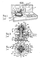
- FIGURE 1 is a perspective view of an analyzer and the test module or reagent handling device of the present invention for use therewith mounted in its operative position on said instrument;
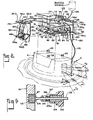
- FIGURE 2 is a perspective view of the test module with certain of its components being illustrated in an exploded configuration;
- FIGURE 3 is a vertical longitudinal sectional view taken on line 3-3 of FIGURE 2 and showing the internal construction of the control valve assembly and its drive; 4
- FIGURE 4 is a sectional view taken on line 4-4 of FIGURE 3, and showing the several tubing or conduit connections to the control valve, and the encoding plate associated therewith; and
- FIGURE 5 is a horizontal sectional view illustrating the connector assembly for connecting the tubing or conduit to each part of the valve assembly.
- FIGURE 1 shows a pictorially the Impact 400 Clinical Spectrophotometer Analyzer presently commercially available in the art, and which is seen to comprise a desk type cabinet B having a generally horizontally disposed work platform S and a rear upstanding supporting panel P.
- The platform S houses suitable computer control circuitry which, as will be understood in the art, is capable of programming the analyzer to automatically perform the test procedures such as are hereinafter described.
- A turntable T is supported on the platform S and carries a plurality of cups or vessels in a particular array which are used in the performance of certain of said test procedures using a test module described below.
- A dispensing probe C is supported over the turntable T at the dispensing position D and is movable, in a manner more fully explained below, over the aforesaid cups or vessels to dispense the serum sample and associated buffer and reagent materials into and out of said cups in the performance of the biochemistry assays.
- A keyboard K disposed within the platform S is used by the clinical technician to program the analyzer and thus to preselect the parameters of the test procedures to be undertaken and to initiate and to terminate the same in a manner well understood in the art.
- A reading or testing station R is located near the left side of the platform S at which a predetermined volume of the material to be tested may be withdrawn from one of the cups of said array and presented to the spectrophotometer of the instrument wherein an absorbance and/or fluoroscopic examination thereof is undertaken.
- A suitable tape printer V and a visual digital display N carried within the panel P provides a permanent record as well as an instantaneous visual display of the analytic results of the biochemistry assay undertaken.
- The test module M is mounted over the turntable T and the dispensing probe C and is operable with said probe C to dispense certain dilution and/or reagent materials into the test cups or vessels.
- With reference now directed to FIGURES 1 and 2 in the present embodiment of analyzer instrument, the turntable T is circular in configuration and formed with three concentrically spaced sets or series of holes identified at hl, h2 and h3' respectively. One hole from each series is centred on a single radius line of the turntable T and referred to herein as an assay test position identified for example, by a single numeral reference "1, 2, 3, 4, ..O etc."
- For example, as best seen in FIGURE 2 a
single radius line 1 of the turntable extends through the centre of one of the holes h1, h2 and h3 of each series and is defined as test position "1". Similar test positions spaced radially about the centre of the turntable are also identified by the reference numerals "2", "3", "4", .."O" etc. - An open top serum cups is disposed in each hole of the innermost series of holes h1 and is intended to accept a human serum sample which is to be analyzed.
- A dilution cup d is disposed in each hole of the intermediate series of holes h2, being thus radially spaced outwardly on its associated radius line from the serum cup s at said test position "1", "2", etc., and is intended to accommodate therein a predetermined portion of the serum sample taken from the serum cup at said position and which is dispensed therein along with a dilution material effective to provide therein a dilution of the said serum sample.
- A reaction cup r is disposed in each hole of the outermost series of holes h3 in radial outwardly spaced relation to its associated dilution cup d at each said test position, and is intended to accommodate a predetermined volume of the diluted serum sample taken by the test module from its associated dilution cup at said test position and which is then dispensed into said reaction cup along with one or several reagent materials whereat a consequent reaction of said dispensed diluted serum and reagent materials occurs.
- The turntable T is actuated in a step-by-step manner by a turntable drive provided with said instrument to present the cups serially and sequentially at each test position to the overlying dispensing probe C and test module whereby the above serum, dilution and reagent material dispensing procedure is repeated.
- The reaction of the serum and reagent materials disposed in each reaction cup r continues while the turntable T is stepped in a clockwise direction as viewed in FIG. 1, and at the completion of a preselected "incubation period" the turntable T has carried said cup r to the instrument reading or testing station R. As aforementioned, a predetermined volume of the incubated serum-reagent mixture is then aspirated out of the reaction cup and placed into a cuvette of the instrument spectrophotometer whereat its absorptivity and/or fluorescence is measured, visually indicated and recorded by said instrument in a manner as will be understood.
- With reference now directed to FIGS. 1 and 2, the test module or reagent handling device is mountable on top of the turntable T in the position illustrated in FIG. 1, so as to be accessible to the underlying dispenser probe C, and for this purpose the module includes a base platform or
plate 20 which is generally rectangular in configuration and adapted to lie on the top surface of thehousing 21 of the dispenser probe C. Suitable fastening means such asposts 23 carried on thehousing 21 and which are adapted to project intoapertures 25 in thebase plate 20 and suitably locked therein by slidable lock plate 26 slidably disposed onplate 20 may be used to secure thebase plate 20 releasably to saidhousing 21. - A dispensing
turret valve assembly 30 is mounted bybracket member 32 in an upright vertical position adjacent one end of plate 20 (right end as depicted in FIG. 1) in proximity to the dispensing probeC. Turret assembly 30 is operable in a manner to be described to selectively dispense serum sample, dilution material and several reagent materials into and out of the aforementioned cup units carried on the turnable T. - For this purpose, the turret valve assembly, as best seen in FIG. 3, comprises a
valve plug member 35 which is of truncated conical shape mounted on the upper end of shaft member 36. It is contemplated thatplug member 35 and shaft member 36 may be made in one piece.Plug member 35, as best seen in FIG. 3 is provided with aninternal channel 39 which is L-shaped in cross-section formed of connectingchannel legs Plug member 35 is disposed centrally within acomplementary cavity 40 formed inturret housing 41 which is basically of square cross-section as viewed in FIG. 2. Turrethousing 41 is formed with a plurality of ports identified at 42, 43, 44 and 45, each of which is spaced 90° from its adjacent port on either side and is seen to project through one side wall of the housing to communicate at its inner end with the centrally disposedcavity 40.Housing 41 is also provided with aport 47 formed in its top wall as viewed in FIG. 3 and which projects downwardly centrally therethrough to connect at its inner end with thechannel leg 39a formed inplug member 35. - The
plug member 35 is intended to be rotated within theturret housing 41 to connect thechannel leg 39b selectively with one of theports channel legs 39a. - As best seen in Fig. 3, the shaft member 36 is rotatably suspended between the
aforementioned bracket member 32 andbase platform 20. Turrethousing 41 is fixedly supported on the upper surface ofbracket member 32 being suitably attached thereto byfasteners 48. -
Coupling 50 receives the lower end of shaft member 36 and is keyed thereto bypin 52 being thus rotatable therewith. Acircular encoding plate 54 referred to below is secured to the upper face ofcoupling 50 and likewise is rotatable therewith. - A
drive hub 55 has a centrally disposedrecess 56 into which is disposed boss element 58 formed integrally on the underside of saidcoupling 50.Pin 60 extending sectorally through thedrive hub 55 engages aflat coupling surface 62 formed on boss element 58 and thus drivingly interconnects the same. - A pair of driving
pins 65 provided on the underside ofdrive hub 55 project downwardly therefrom and extend into apertures 67 formed inexternal gear element 70. Said gear element is rotatably supported on bearing 72 carried on the top surface ofplatform 20 being secured thereto byfastener 73. - A
coil spring 75 disposed on shaft member 36 has its upper end engaging the underside ofplug member 35 and its lower end disposed withinretainer nut 77 suitably secured to the shaft member 36, being thus effective to urge theplug member 35 into pressure engagement with the complementary wall ofhousing cavity 40 and thereby provide a substantially liquid-light relation therebetween. - With this turret assembly as thus described, rotation of
gear element 70 is effective to cause a corresponding rotation to theplug member 35. Such rotation is caused by astepping motor 80 FIG. 2 of conventional design supported onflat plate member 81, which, in turn, is supported onposts platform 20. Shaft 84 of said stepping motor extends into thespace 85 betweenplatform 20 andplate member 81 and has a drive gear 87 securely attached thereto.Follower gear 90 is mounted on shaft 91 rotatably supported between saidplatform 20 andplate member 81, and thus drivingly meshes with drive gear 87.Pinion gear 93 is carried on shaft 91 belowfollower gear 90 and is rotatably driven with said shaft. A suitableendless drive belt 94 having internal drive teeth is placed over and meshes withgear element 70 andpinion gear 93 to connect saidgear element 70 drivingly to said pinion gear. - With this assembly, upon the excitation of stepping
motor 80, thevalve plug member 35 is rotatable within thehousing cavity 40 to selectively connect one of the ports 42-45 tochannel leg 39b and hence to connect said selected port tochannel leg 39a of said plug member. In the present embodiment of test module, it is intended that each actuation of steppingmotor 80 will cause a corresponding 90° rotation to theplug member 35. - As mentioned above, a suitable buffer or dilution material is to be dispensed by the test module along with a predetermined quantity of serum into a dilution cup d preparatory to the assay thereof.
- For this purpose, the turret housing, as best seen in FIGS. 3 and 5, is provided with
entry port 47 formed in the top wall of saidhousing 41 and extending therethrough and communicating with thechannel leg 39a ofplug member 35. - A
flanged nut 102, formed in its present configuration of a suitable plastic such as nylon, has one end of aflexible tube 103 projecting centrally therethrough and terminating in a flaredend 104. Aplug 105 is slidably disposed over the flaredend 104 of said tube and is provided withstem portion 105a of reduced diameter to defineannular shoulder 106 upon which seats one end ofcoil spring 107, the other end of said spring seating within the externally threadedboss 109 of said flangednut 102. The flaredend 104 oftube 103 is placed intoentry port 47 and engagesseat 112 provided at the inner end of said port. Upon threading thenut 102 into said port, thecoil spring 107 provides suitable pressure against said flared end to provide a liquid-tight seal between it andseat 112. - The opposite end of
tube 103, as seen in FIG. 2, connects to the output end of aheater coil 115 of abuffer heater 118 which comprises thecoil 115 wrapped around a spool shapedheated element 121 which is connected to the instrument control and operable to heat the buffer or dilution material passing therethrough to a temperature within a preferred range of 35°C to 45°C. The buffer heater is disposed in close proximity to and behind theturret assembly 30, and supported abovebracket member 32. - The inlet end of
heater coil 115 is connected bytubing 125 to a suitable supply or buffer or dilution fluid such as distilled water carried in bottle B mounted on the instrument panel P. - Buffer fluid is manipulated for aspirating and dispensing by an automatic pipette/dilutor or reversably actuatable syringe of the analyzer which is effective to aspirate diluted serum out of a dilution cup and thence subsequently to dispense said diluted serum and a selected reagent material into a reaction cup carried on turntable or transport T.
- For this purpose, a
plate 130 is mounted on each side of thebracket member 32 and has avertical wall portion 130a depending downwardly from said bracket and extending below thebase platform 20. As seen in FIG. 2, eachplate 130 is generally inverted L-shaped in cross-section, having a flat horizontally disposedshort wall portion 130b projecting outwardly from its associatedvertical wall portion 130a. As best seen in FIG. 2, each shorthorizontal wall portion 130b is provided with a pair of spacedapertures 145 into each of which is releasably disposed a coupling member, each of which is identified at 146a, 146b, 146c. - A pair of
retainer clips 148, generally U-shaped in configuration, is swingably attached at the opposed free ends thereof to arod member 150 disposed behind thevertical wall portion 130a of eachplate 130. Coil springs 151 carried on eachrod member 150 are connectable to the aforesaid ends of eachclip 148 being operable to urge said clips to extend substantially perpendicularly outwardly from theabove wall portion 130b of saidplate 130. - As seen in FIG. 2, each said clip is intended to be swung downwardly about its ends to permit the placement of a reagent bottle or the like, as identified at 154, 154a and 154b to capture the bottle between the coupling and the clip.
- A length of
tubing 160 which, in its present form, is metal has its upper end disposed in eachcoupling member 146a-146c, saidtubing 160 projecting downwardly therefrom and into the bottle disposed therebelow. As seen in FIG. 2, the bottom portion of each saidtubing 160 bends slightly inwardly towards thevertical wall portion 130a. In addition, the bottom end of eachtubing 160 is formed at an angle of approximately 45° to the tubing longitudinal axis in order to prevent the tubing from being inadvertently sealed when it is held in place against the bottom of thereagent bottle - As best seen in FIG. 2, a length of
tubing 163 has one end attached to one end of ashort tube 164, the opposite end of which is connectable tocoupling member 146a and communicates via said coupling with thetubing 160. The opposite end oftubing 163 is connected toinlet port 42 in the side wall 41b ofturret housing 41 preferably by the same termination assembly as previously described to connect the heated buffer material viaflexible tube 103 toentry port 47. - In like manner, one end of a
flexible tube inlet ports side wall 41a and 41c respectively, of saidturret housing 41, the opposite end oftube 165 connecting to one end ofmetal tube 168, the opposite end of which connects tocoupling member 146b, and the opposite end oftube 166 similarly connecting with one end ofmetal tube 169, the opposite end of which connects tocoupling member 146c. - In the present configuration of test module, the bottle 154d connecting with the remaining
coupling member 146d inhousing side wall 41d may be utilized as a waste position for certain test procedures whereby said bottle may alternately be connectable to one of the ports of the valve and positioned to collect the reaction sample at the completion of its analysis. - As best seen in FIGURE 2, the
turret housing 41 is connectable to the dispensing probe C, and for this purpose, one end offlexible tubing 176 is connected tohousing port 45 using the same tubing termination assembly as previously described herein with respect toentry port 47. The opposite end of saidtubing 176 may be suitably connected to the dispensing probe C, and is of sufficient length to permit said probe to move freely to its several dispensing and/or aspirating positions, as will be presently described. - As previously mentioned, each actuation of the stepping
motor 80 is intended to correspondingly rotate thevalve plug member 35 ninety degrees (90°). - To accomplish this, the
aforementioned encoding plate 54 carried oncoupling 50 is provided with four slots, each having a particular configuration as identified at 190-193, respectively, each of said slots being spaced 90° about the perimeter of said plate from its adjacent slot, as best seen im FIG. 4. - A
sensor head 200, FIG. 3, is supported at one side of theencoding plate 54 and comprises twoflat plates 200a and 200b disposed in spaced relation to each other on opposite sides of saidplate 54 to permit the latter to freely pass therebetween.Sensor plate 200a carries a set of transmitter type transducers orsensors valve plug member 35. - Sensor plate 200b carries three receiver-type transducers or
sensor elements 206a, 206b and 206c, each of which is located directly below one of thetransducers - As best seen in FIGS. 3 and 4, the sensor pairs coact with the slots 190-193 in the
encoding plate 54 to program the operation of the analyzer instrument as will be understood in analysis of a serum sample under test. - More particularly, as seen in FIG. 4,
slot 190 is T-shaped in configuration with the stem of the T projecting radially into theplate 54 from its periphery and with the top or bar of the T extending perpendicularly thereto. The dimension of theslot 190 is such that when it is centred between theplates 200a and 200b of thesensor head 200, each sensor pair i.e. (204a, 206a; 204b, 206b; 204c, 206c) is likewise centred within the top or bar part thereof and adjacent opposite ends thereof as pictorially illustrated in FIG. 4 and are in their activated mode. In the present instrument operation, this position is also referred to as the "home position" or "dispenser probe" position in which position, as is more fully described below, the probe C is operable to aspirate the test sample out of a sample cup and dispense said sample and one or more buffer materials into the dilution cup. Likewise, at the home position, the dispenser probe C is operable to aspirate a predetermined volume of diluted serum out of a dilution cup and thereafter to dispense the diluted serum along with one or more reagent materials serially into a reaction cup. -
Encoding plate slot 191, as seen in FIG. 4, is of inverted L shape with oneleg 191a projecting radially into theplate 54 from its periphery and located 90° from the stem portion of T-shapedslot 190. Theslot leg 191a connects at its inner end with theother leg 191b which extends perpendicularly and to the left as viewed in FIG. 4. -
Slot 191 is dimensioned such that when it is centred between theplates 200a and 200b ofsensor head 200only sensor pairs 204b, 206b and 204c, 206c are activated andsensor pair - In the present instrument, when
slot 191 is centred withinsensor head 200 the instrument is programmed to provide a suitable antibody enzyme to the probe C preparatory to dispensing the same into a reaction cup. -
Slot 192 is of rectangular configuration being spaced 90° fromslot 191 on saidplate 54 and projecting radially into the same from its periphery.Slot 192 is dimensioned such that when it is centred within thesensor head 200 both pairs (204a, 206a and 204b, 206b) of the aforesaid sensors are inactivated, whilepair 204c, 206c is activated. - In the present instrument, when
rectangular slot 192 is centred within thesensor head 200 the instrument is programmed to provide for a protein chemistry assay. -
Slot 193, as seen in FIG. 4, is of reverse L-shaped configuration with one leg 193a projecting radially inwardly into theplate 54 from its periphery, being located clockwise 90° from therectangular slot 192. The slot leg 193a connects at its inner end with the other leg 193b which projects perpendicularly and to the left therefrom.Slot 193 is dimensioned such that when it is centred within thesensor head 200 only thesensor pairs - With the above described apparatus as incorporated for use with above identified Impact 400 instrument, a typical operational cycle is as follows.
- As previously mentioned the Impact 400 type of instrument is a microprocessor controlled clinical chemistry analyzer in which the operator uses the instrument keyboard to program and preselect the test analysis to be undertaken by said instrument.
- In using the present test module with this type of instrument the microprocessor is interconnected with the module in a manner as is understood in the art whereby the
buffer heater 118 is connected into the microprocessor circuitry and controlled thereby so as to maintain the dilution liquid material passing therethrough at a temperature in the range of 35°C to 45°C. Also, the steppingmotor 80 is connected to said instrument control circuitry so as to be periodically actuatable to step thevalve plug member 35 andsensor plate 54 selectively to one of its four positions during a sample test procedure. - Assuming, as viewed in FIG. 2, that serum cups s are disposed in the circle of holes hl, each containing a serum sample to be analyzed, the dilution cups d are disposed in the circle of holes h2 and the reaction cups r are disposed in the circle of holes h3, and further assuming that the dispenser probe C is located over the "
test position 1" as viewed in FIG. 1, and the test module has theencoding plate slot 190 disposed centrally within thesensor head 200 whereby the test module is at its "home position", the operator may actuate the microprocessor and initiate a typical assay whereby the dispense probe C moves downwardly into the serum cup s attest position 1. The reversable syringe of said instrument is then actuated to aspirate or withdraw a suitable volume of serum, as for example approximately 8 microlitres, from said cup and up into thetubing 176 connecting withvalve port 45. The probe C moves out over the dilution cup d at saidtest position 1 whereat the withdrawn serum sample and a suitable quantity of heated dilution material, for example approximately 400 microlitres, from the dilution source are dispensed serially into said dilution cup to provide an approximate 50:1 dilution. - The probe C is then raised, the stepping
motor 80 actuated to rotate thevalve plug 35 andencoding plate 90° clockwise as viewed in FIG. 4 whereby the fluorescein drug reagent material inbottle 154b is connected to thevalve plug member 35 and upon programmable actuation of the reversible syringe a predetermined volume (for example 20 microlitres) of said reagent material is sucked intotubing 103. - Concurrently, the turntable transport T is stepped clockwise as viewed in FIG. 2 to bring the last preceding
test position 2 under the probe C. The probe C is then lowered into the reaction cup r at thetest position 2 and concurrently stepping motor is actuated to rotatevalve plug 35 andencoding plate 90° counterclockwise. The fluorescein drug reagent material is then dispensed into said reaction cup throughtubing test position 2. - The probe C is again raised, and the turntable transport T is reversibly stepped counterclockwise as viewed in FIG. 2 to again locate said probe C over
test position 1. At the same time thevalve plug member 35 andencoding plate 54 are stepped by the actuation of steppingmotor 80 90° counterclockwise as seen in FIGURE 4 to locateencoding slot 191 between the plates of thesensor 200. Antibody enzyme inreagent bottle 154c is then drawn by the instrument syringe out of said bottle and intotubing 103. - The
valve plug member 35 andencoding plate 54 are then stepped by steppingmotor 80 clockwise 90° as viewed in FIG. 4 to return theencoding slot 190 between the plates of thesensor 200 or to the "home position". - The probe C is then extended into the dilution cup d at
test position 1 whereat a predetermined volume of the diluted serum sample in said dilution cup is aspirated or sucked out thereof and intotubing 176. - The probe C is then extended out over the reaction cup r at said
test position 1, the probe lowered into said cup and the diluted serum sample is dispensed into said reaction cup r serially with the antibody-enzyme fromtubing 103 and a suitable volume of dilution material. - The probe C is again raised out of the reaction cup at
test position 1 and the turntable transport T is stepped counterclockwise as viewed in FIGURE 2 to locate the probe C at the next test position 0 at which the cycle just described is repeated. - After a preselected incubation period each reaction cup carrying the sample test mixture, i.e. serum sample, dilution material, antibody enzyme and fluorescein reagent material is moved individually by the turntable transport T to the reading station R whereat a predetermined volume of said mixture is aspirated out of said cup and presented to the spectrophotometer of said instrument wherein its absorption and/or fluorescent analysis is undertaken.
- Although the above description relates to a preferred embodiment of test module or reagent handling device of the present invention and the manner in which it is used with a typical clinical analyzer for performing a plurality of biochemistry assays and immunoassays, it will be realized that various modifications may be made within the scope of the invention.
Claims (16)
Applications Claiming Priority (2)
| Application Number | Priority Date | Filing Date | Title |
|---|---|---|---|
| US06/405,764 US4737342A (en) | 1982-08-06 | 1982-08-06 | Test module |
| US405764 | 2003-04-01 |
Publications (3)
| Publication Number | Publication Date |
|---|---|
| EP0101192A2 true EP0101192A2 (en) | 1984-02-22 |
| EP0101192A3 EP0101192A3 (en) | 1984-05-23 |
| EP0101192B1 EP0101192B1 (en) | 1987-05-27 |
Family
ID=23605130
Family Applications (1)
| Application Number | Title | Priority Date | Filing Date |
|---|---|---|---|
| EP83304116A Expired EP0101192B1 (en) | 1982-08-06 | 1983-07-15 | Test module for a clinical analyzer |
Country Status (4)
| Country | Link |
|---|---|
| US (1) | US4737342A (en) |
| EP (1) | EP0101192B1 (en) |
| JP (1) | JPS5944662A (en) |
| DE (1) | DE3371816D1 (en) |
Cited By (1)
| Publication number | Priority date | Publication date | Assignee | Title |
|---|---|---|---|---|
| EP0286536A1 (en) * | 1987-04-09 | 1988-10-12 | Compagnie Generale Des Matieres Nucleaires (Cogema) | Stepping rotative conveyor and sampling device provided with such a conveyor |
Families Citing this family (27)
| Publication number | Priority date | Publication date | Assignee | Title |
|---|---|---|---|---|
| AT391213B (en) * | 1987-05-12 | 1990-09-10 | Avl Verbrennungskraft Messtech | DEVICE FOR SELECTIVE FEEDING OF AN ANALYZER |
| US6436349B1 (en) | 1991-03-04 | 2002-08-20 | Bayer Corporation | Fluid handling apparatus for an automated analyzer |
| US20060013729A1 (en) * | 1991-02-14 | 2006-01-19 | Glen Carey | Fluid handling apparatus for an automated analyzer |
| CA2384519C (en) * | 1991-03-04 | 2006-08-15 | Bayer Corporation | Automated analyzer |
| US6498037B1 (en) | 1991-03-04 | 2002-12-24 | Bayer Corporation | Method of handling reagents in a random access protocol |
| US5376313A (en) * | 1992-03-27 | 1994-12-27 | Abbott Laboratories | Injection molding a plastic assay cuvette having low birefringence |
| US5635364A (en) * | 1992-03-27 | 1997-06-03 | Abbott Laboratories | Assay verification control for an automated analytical system |
| US5575978A (en) * | 1992-03-27 | 1996-11-19 | Abbott Laboratories | Sample container segment assembly |
| US6190617B1 (en) | 1992-03-27 | 2001-02-20 | Abbott Laboratories | Sample container segment assembly |
| US5540890A (en) * | 1992-03-27 | 1996-07-30 | Abbott Laboratories | Capped-closure for a container |
| US5627522A (en) * | 1992-03-27 | 1997-05-06 | Abbott Laboratories | Automated liquid level sensing system |
| US5610069A (en) * | 1992-03-27 | 1997-03-11 | Abbott Laboratories | Apparatus and method for washing clinical apparatus |
| US5960160A (en) * | 1992-03-27 | 1999-09-28 | Abbott Laboratories | Liquid heater assembly with a pair temperature controlled electric heating elements and a coiled tube therebetween |
| US5646049A (en) * | 1992-03-27 | 1997-07-08 | Abbott Laboratories | Scheduling operation of an automated analytical system |
| US5578494A (en) * | 1992-03-27 | 1996-11-26 | Abbott Laboratories | Cap actuator for opening and closing a container |
| US5605665A (en) * | 1992-03-27 | 1997-02-25 | Abbott Laboratories | Reaction vessel |
| US5536471A (en) * | 1992-03-27 | 1996-07-16 | Abbott Laboratories | Syringe with bubble flushing |
| US5507410A (en) * | 1992-03-27 | 1996-04-16 | Abbott Laboratories | Meia cartridge feeder |
| USD349861S (en) | 1992-07-20 | 1994-08-23 | Abbott Laboratories | Automated analytical instrument |
| JP3786724B2 (en) * | 1994-08-11 | 2006-06-14 | エスアイアイ・ナノテクノロジー株式会社 | Inductively coupled plasma analyzer and its sample introduction device |
| US5599501A (en) * | 1994-11-10 | 1997-02-04 | Ciba Corning Diagnostics Corp. | Incubation chamber |
| US5856194A (en) | 1996-09-19 | 1999-01-05 | Abbott Laboratories | Method for determination of item of interest in a sample |
| US5795784A (en) | 1996-09-19 | 1998-08-18 | Abbott Laboratories | Method of performing a process for determining an item of interest in a sample |
| US6063634A (en) * | 1998-04-01 | 2000-05-16 | Abbott Laboratories | Fluid assembly and method for diagnostic instrument |
| WO2001006429A1 (en) * | 1999-07-15 | 2001-01-25 | Shea Robert S | Method of sequencing chronic disease testing, reporting and evaluation |
| US7250303B2 (en) | 2001-07-20 | 2007-07-31 | Ortho-Clinical Diagnostics, Inc. | Chemistry system for a clinical analyzer |
| JP4251627B2 (en) * | 2003-09-19 | 2009-04-08 | 株式会社東芝 | Chemical analyzer and dispensing method thereof |
Family Cites Families (14)
| Publication number | Priority date | Publication date | Assignee | Title |
|---|---|---|---|---|
| US3449959A (en) * | 1966-06-27 | 1969-06-17 | Bausch & Lomb | Sample container for automatic sampling apparatus |
| US3536450A (en) * | 1969-06-11 | 1970-10-27 | Univ California | System for analyzing compounds |
| CA950703A (en) * | 1970-04-03 | 1974-07-09 | Manuel C. Sanz | Automatic test tube transporter and sample dispenser |
| US3802782A (en) * | 1970-08-19 | 1974-04-09 | Rohe Scientific Corp | Chemical analyzer performing sequential analysis of samples |
| US3788816A (en) * | 1972-03-02 | 1974-01-29 | Beckman Instruments Inc | Chemical analysis rotary module |
| US3912456A (en) * | 1974-03-04 | 1975-10-14 | Anatronics Corp | Apparatus and method for automatic chemical analysis |
| US3901084A (en) * | 1974-07-19 | 1975-08-26 | Harrison D Brailsford | Vacuum-operated sampler and distributor for multiple sampling operation |
| JPS5916667B2 (en) * | 1975-02-28 | 1984-04-17 | トウアイヨウデンシ カブシキガイシヤ | automatic blood analyzer |
| US4058367A (en) * | 1976-05-19 | 1977-11-15 | Gilford Instrument Laboratories Inc. | Automatic asynchronous fluid processing apparatus |
| US4155978A (en) * | 1977-04-27 | 1979-05-22 | Nihon Denshi Kabushiki Kaisha | Automatic chemical analyzer |
| IT1155827B (en) * | 1978-02-15 | 1987-01-28 | Welch Henry H | AUTOMATIC MULTI-CHANNEL APPARATUS TO CARRY OUT ANALYSIS ON FLUIDS, IN PARTICULAR CHEMICAL-CLINICAL ANALYSIS ON BIOLOGICAL LIQUIDS |
| US4156437A (en) * | 1978-02-21 | 1979-05-29 | The Perkin-Elmer Corporation | Computer controllable multi-port valve |
| JPS55144550A (en) * | 1979-04-28 | 1980-11-11 | Olympus Optical Co Ltd | Automatic analyzer |
| US4322216A (en) * | 1981-02-26 | 1982-03-30 | Beckman Instruments, Inc. | Method and apparatus for positioning cars in a sample handling apparatus |
-
1982
- 1982-08-06 US US06/405,764 patent/US4737342A/en not_active Expired - Fee Related
-
1983
- 1983-07-15 EP EP83304116A patent/EP0101192B1/en not_active Expired
- 1983-07-15 DE DE8383304116T patent/DE3371816D1/en not_active Expired
- 1983-08-01 JP JP58139522A patent/JPS5944662A/en active Pending
Cited By (3)
| Publication number | Priority date | Publication date | Assignee | Title |
|---|---|---|---|---|
| EP0286536A1 (en) * | 1987-04-09 | 1988-10-12 | Compagnie Generale Des Matieres Nucleaires (Cogema) | Stepping rotative conveyor and sampling device provided with such a conveyor |
| FR2613704A1 (en) * | 1987-04-09 | 1988-10-14 | Cogema | STEP-BY-STEP ROTARY CONVEYOR AND LIQUID SAMPLING SYSTEM COMPRISING SUCH A CONVEYOR |
| US4854355A (en) * | 1987-04-09 | 1989-08-08 | Cogema-Compagnie Generale Des Matieres Nucleaires | Stepwise advancing rotary conveyor and installation for taking liquid samples incorporating such a conveyor |
Also Published As
| Publication number | Publication date |
|---|---|
| DE3371816D1 (en) | 1987-07-02 |
| US4737342A (en) | 1988-04-12 |
| EP0101192A3 (en) | 1984-05-23 |
| JPS5944662A (en) | 1984-03-13 |
| EP0101192B1 (en) | 1987-05-27 |
Similar Documents
| Publication | Publication Date | Title |
|---|---|---|
| EP0101192B1 (en) | Test module for a clinical analyzer | |
| US7855084B2 (en) | Chemistry system for clinical analyzer | |
| US4933147A (en) | Unitized reagent containment system for clinical analyzer | |
| JP3214895B2 (en) | Reagent pack for immunoassay | |
| CA1335345C (en) | Test card for performing assays | |
| JP3677298B2 (en) | Automatic chemical analyzer | |
| KR100920652B1 (en) | Automatic alignment of weighing systems for biochemical meters | |
| CA1296403C (en) | Automated patient sample analysis instrument | |
| AU636568B2 (en) | Reaction cartridge and carousel for biological sample analyzer | |
| CA1335383C (en) | Apparatus and method for providing assay calibration data | |
| US4346056A (en) | Automatic analyzing apparatus | |
| EP1906187B1 (en) | Auxiliary Sample Supply for a Clinical Analyzer | |
| US6299839B1 (en) | System and methods for performing rotor assays | |
| AU596799B2 (en) | Unitized reagent containment system for clinical analyzer | |
| JP2008532048A (en) | Automatic analyzer | |
| AU636571B2 (en) | Biological sample analyzer | |
| EP0336309A2 (en) | A selective or sequential access analyzer for clinico-chemical analyses and for immunological tests | |
| JPH03285168A (en) | Sample dispensing device |
Legal Events
| Date | Code | Title | Description |
|---|---|---|---|
| PUAI | Public reference made under article 153(3) epc to a published international application that has entered the european phase |
Free format text: ORIGINAL CODE: 0009012 |
|
| AK | Designated contracting states |
Designated state(s): DE FR GB |
|
| PUAL | Search report despatched |
Free format text: ORIGINAL CODE: 0009013 |
|
| AK | Designated contracting states |
Designated state(s): DE FR GB |
|
| 17P | Request for examination filed |
Effective date: 19841018 |
|
| 17Q | First examination report despatched |
Effective date: 19860320 |
|
| GRAA | (expected) grant |
Free format text: ORIGINAL CODE: 0009210 |
|
| AK | Designated contracting states |
Kind code of ref document: B1 Designated state(s): DE FR GB |
|
| REF | Corresponds to: |
Ref document number: 3371816 Country of ref document: DE Date of ref document: 19870702 |
|
| ET | Fr: translation filed | ||
| PLBE | No opposition filed within time limit |
Free format text: ORIGINAL CODE: 0009261 |
|
| STAA | Information on the status of an ep patent application or granted ep patent |
Free format text: STATUS: NO OPPOSITION FILED WITHIN TIME LIMIT |
|
| 26N | No opposition filed | ||
| PGFP | Annual fee paid to national office [announced via postgrant information from national office to epo] |
Ref country code: GB Payment date: 19890630 Year of fee payment: 7 |
|
| PGFP | Annual fee paid to national office [announced via postgrant information from national office to epo] |
Ref country code: FR Payment date: 19890719 Year of fee payment: 7 |
|
| PGFP | Annual fee paid to national office [announced via postgrant information from national office to epo] |
Ref country code: DE Payment date: 19890727 Year of fee payment: 7 |
|
| PG25 | Lapsed in a contracting state [announced via postgrant information from national office to epo] |
Ref country code: GB Effective date: 19900715 |
|
| GBPC | Gb: european patent ceased through non-payment of renewal fee | ||
| PG25 | Lapsed in a contracting state [announced via postgrant information from national office to epo] |
Ref country code: FR Effective date: 19910329 |
|
| PG25 | Lapsed in a contracting state [announced via postgrant information from national office to epo] |
Ref country code: DE Effective date: 19910403 |
|
| REG | Reference to a national code |
Ref country code: FR Ref legal event code: ST |