EP0101213B1 - Brûleur et appareil pour la gazéification de charbon - Google Patents
Brûleur et appareil pour la gazéification de charbon Download PDFInfo
- Publication number
- EP0101213B1 EP0101213B1 EP19830304274 EP83304274A EP0101213B1 EP 0101213 B1 EP0101213 B1 EP 0101213B1 EP 19830304274 EP19830304274 EP 19830304274 EP 83304274 A EP83304274 A EP 83304274A EP 0101213 B1 EP0101213 B1 EP 0101213B1
- Authority
- EP
- European Patent Office
- Prior art keywords
- burner
- face
- manifold
- discharge
- fluid
- Prior art date
- Legal status (The legal status is an assumption and is not a legal conclusion. Google has not performed a legal analysis and makes no representation as to the accuracy of the status listed.)
- Expired
Links
- 239000003245 coal Substances 0.000 title description 3
- 238000002309 gasification Methods 0.000 title 1
- 239000012530 fluid Substances 0.000 claims description 23
- 238000002485 combustion reaction Methods 0.000 claims description 13
- 238000006243 chemical reaction Methods 0.000 claims description 11
- 239000000203 mixture Substances 0.000 claims description 11
- 239000000446 fuel Substances 0.000 claims description 9
- 230000003647 oxidation Effects 0.000 claims description 9
- 238000007254 oxidation reaction Methods 0.000 claims description 9
- 230000004888 barrier function Effects 0.000 claims description 7
- 230000002093 peripheral effect Effects 0.000 claims description 4
- 239000000463 material Substances 0.000 claims description 3
- 230000008021 deposition Effects 0.000 claims description 2
- 239000002893 slag Substances 0.000 description 12
- 238000001816 cooling Methods 0.000 description 10
- QVGXLLKOCUKJST-UHFFFAOYSA-N atomic oxygen Chemical compound [O] QVGXLLKOCUKJST-UHFFFAOYSA-N 0.000 description 9
- 229910052760 oxygen Inorganic materials 0.000 description 9
- 239000001301 oxygen Substances 0.000 description 9
- 230000035508 accumulation Effects 0.000 description 8
- 238000009825 accumulation Methods 0.000 description 8
- 239000002826 coolant Substances 0.000 description 6
- 239000002245 particle Substances 0.000 description 6
- XLYOFNOQVPJJNP-UHFFFAOYSA-N water Substances O XLYOFNOQVPJJNP-UHFFFAOYSA-N 0.000 description 6
- 239000007789 gas Substances 0.000 description 5
- 239000007787 solid Substances 0.000 description 5
- 239000004215 Carbon black (E152) Substances 0.000 description 4
- 239000003250 coal slurry Substances 0.000 description 4
- 229930195733 hydrocarbon Natural products 0.000 description 4
- 150000002430 hydrocarbons Chemical class 0.000 description 4
- 230000015572 biosynthetic process Effects 0.000 description 3
- 239000004020 conductor Substances 0.000 description 3
- 239000013618 particulate matter Substances 0.000 description 3
- 230000005855 radiation Effects 0.000 description 3
- 239000011819 refractory material Substances 0.000 description 3
- 238000003786 synthesis reaction Methods 0.000 description 3
- CURLTUGMZLYLDI-UHFFFAOYSA-N Carbon dioxide Chemical compound O=C=O CURLTUGMZLYLDI-UHFFFAOYSA-N 0.000 description 2
- 229910000831 Steel Inorganic materials 0.000 description 2
- 230000002411 adverse Effects 0.000 description 2
- 239000011449 brick Substances 0.000 description 2
- 229910002092 carbon dioxide Inorganic materials 0.000 description 2
- 239000000498 cooling water Substances 0.000 description 2
- 238000010438 heat treatment Methods 0.000 description 2
- 239000003779 heat-resistant material Substances 0.000 description 2
- 229910001026 inconel Inorganic materials 0.000 description 2
- 239000007788 liquid Substances 0.000 description 2
- 238000004519 manufacturing process Methods 0.000 description 2
- 230000001105 regulatory effect Effects 0.000 description 2
- 230000008439 repair process Effects 0.000 description 2
- 239000010959 steel Substances 0.000 description 2
- 230000002459 sustained effect Effects 0.000 description 2
- 230000009471 action Effects 0.000 description 1
- 239000001569 carbon dioxide Substances 0.000 description 1
- 238000010276 construction Methods 0.000 description 1
- 230000008602 contraction Effects 0.000 description 1
- 239000012809 cooling fluid Substances 0.000 description 1
- 230000006735 deficit Effects 0.000 description 1
- 238000009413 insulation Methods 0.000 description 1
- 230000001590 oxidative effect Effects 0.000 description 1
- 230000000750 progressive effect Effects 0.000 description 1
- 230000001681 protective effect Effects 0.000 description 1
- 230000009467 reduction Effects 0.000 description 1
- 239000011343 solid material Substances 0.000 description 1
Images


Classifications
-
- C—CHEMISTRY; METALLURGY
- C10—PETROLEUM, GAS OR COKE INDUSTRIES; TECHNICAL GASES CONTAINING CARBON MONOXIDE; FUELS; LUBRICANTS; PEAT
- C10J—PRODUCTION OF PRODUCER GAS, WATER-GAS, SYNTHESIS GAS FROM SOLID CARBONACEOUS MATERIAL, OR MIXTURES CONTAINING THESE GASES; CARBURETTING AIR OR OTHER GASES
- C10J3/00—Production of combustible gases containing carbon monoxide from solid carbonaceous fuels
- C10J3/46—Gasification of granular or pulverulent flues in suspension
- C10J3/48—Apparatus; Plants
- C10J3/50—Fuel charging devices
- C10J3/506—Fuel charging devices for entrained flow gasifiers
-
- C—CHEMISTRY; METALLURGY
- C10—PETROLEUM, GAS OR COKE INDUSTRIES; TECHNICAL GASES CONTAINING CARBON MONOXIDE; FUELS; LUBRICANTS; PEAT
- C10J—PRODUCTION OF PRODUCER GAS, WATER-GAS, SYNTHESIS GAS FROM SOLID CARBONACEOUS MATERIAL, OR MIXTURES CONTAINING THESE GASES; CARBURETTING AIR OR OTHER GASES
- C10J3/00—Production of combustible gases containing carbon monoxide from solid carbonaceous fuels
- C10J3/46—Gasification of granular or pulverulent flues in suspension
- C10J3/48—Apparatus; Plants
- C10J3/52—Ash-removing devices
- C10J3/526—Ash-removing devices for entrained flow gasifiers
-
- C—CHEMISTRY; METALLURGY
- C10—PETROLEUM, GAS OR COKE INDUSTRIES; TECHNICAL GASES CONTAINING CARBON MONOXIDE; FUELS; LUBRICANTS; PEAT
- C10J—PRODUCTION OF PRODUCER GAS, WATER-GAS, SYNTHESIS GAS FROM SOLID CARBONACEOUS MATERIAL, OR MIXTURES CONTAINING THESE GASES; CARBURETTING AIR OR OTHER GASES
- C10J3/00—Production of combustible gases containing carbon monoxide from solid carbonaceous fuels
- C10J3/72—Other features
- C10J3/74—Construction of shells or jackets
-
- C—CHEMISTRY; METALLURGY
- C10—PETROLEUM, GAS OR COKE INDUSTRIES; TECHNICAL GASES CONTAINING CARBON MONOXIDE; FUELS; LUBRICANTS; PEAT
- C10J—PRODUCTION OF PRODUCER GAS, WATER-GAS, SYNTHESIS GAS FROM SOLID CARBONACEOUS MATERIAL, OR MIXTURES CONTAINING THESE GASES; CARBURETTING AIR OR OTHER GASES
- C10J3/00—Production of combustible gases containing carbon monoxide from solid carbonaceous fuels
- C10J3/72—Other features
- C10J3/74—Construction of shells or jackets
- C10J3/76—Water jackets; Steam boiler-jackets
-
- C—CHEMISTRY; METALLURGY
- C10—PETROLEUM, GAS OR COKE INDUSTRIES; TECHNICAL GASES CONTAINING CARBON MONOXIDE; FUELS; LUBRICANTS; PEAT
- C10J—PRODUCTION OF PRODUCER GAS, WATER-GAS, SYNTHESIS GAS FROM SOLID CARBONACEOUS MATERIAL, OR MIXTURES CONTAINING THESE GASES; CARBURETTING AIR OR OTHER GASES
- C10J2200/00—Details of gasification apparatus
- C10J2200/15—Details of feeding means
- C10J2200/152—Nozzles or lances for introducing gas, liquids or suspensions
-
- C—CHEMISTRY; METALLURGY
- C10—PETROLEUM, GAS OR COKE INDUSTRIES; TECHNICAL GASES CONTAINING CARBON MONOXIDE; FUELS; LUBRICANTS; PEAT
- C10J—PRODUCTION OF PRODUCER GAS, WATER-GAS, SYNTHESIS GAS FROM SOLID CARBONACEOUS MATERIAL, OR MIXTURES CONTAINING THESE GASES; CARBURETTING AIR OR OTHER GASES
- C10J2300/00—Details of gasification processes
- C10J2300/09—Details of the feed, e.g. feeding of spent catalyst, inert gas or halogens
- C10J2300/0913—Carbonaceous raw material
- C10J2300/093—Coal
-
- C—CHEMISTRY; METALLURGY
- C10—PETROLEUM, GAS OR COKE INDUSTRIES; TECHNICAL GASES CONTAINING CARBON MONOXIDE; FUELS; LUBRICANTS; PEAT
- C10J—PRODUCTION OF PRODUCER GAS, WATER-GAS, SYNTHESIS GAS FROM SOLID CARBONACEOUS MATERIAL, OR MIXTURES CONTAINING THESE GASES; CARBURETTING AIR OR OTHER GASES
- C10J2300/00—Details of gasification processes
- C10J2300/09—Details of the feed, e.g. feeding of spent catalyst, inert gas or halogens
- C10J2300/0953—Gasifying agents
- C10J2300/0956—Air or oxygen enriched air
-
- C—CHEMISTRY; METALLURGY
- C10—PETROLEUM, GAS OR COKE INDUSTRIES; TECHNICAL GASES CONTAINING CARBON MONOXIDE; FUELS; LUBRICANTS; PEAT
- C10J—PRODUCTION OF PRODUCER GAS, WATER-GAS, SYNTHESIS GAS FROM SOLID CARBONACEOUS MATERIAL, OR MIXTURES CONTAINING THESE GASES; CARBURETTING AIR OR OTHER GASES
- C10J2300/00—Details of gasification processes
- C10J2300/09—Details of the feed, e.g. feeding of spent catalyst, inert gas or halogens
- C10J2300/0953—Gasifying agents
- C10J2300/0959—Oxygen
-
- C—CHEMISTRY; METALLURGY
- C10—PETROLEUM, GAS OR COKE INDUSTRIES; TECHNICAL GASES CONTAINING CARBON MONOXIDE; FUELS; LUBRICANTS; PEAT
- C10J—PRODUCTION OF PRODUCER GAS, WATER-GAS, SYNTHESIS GAS FROM SOLID CARBONACEOUS MATERIAL, OR MIXTURES CONTAINING THESE GASES; CARBURETTING AIR OR OTHER GASES
- C10J2300/00—Details of gasification processes
- C10J2300/09—Details of the feed, e.g. feeding of spent catalyst, inert gas or halogens
- C10J2300/0953—Gasifying agents
- C10J2300/0969—Carbon dioxide
-
- C—CHEMISTRY; METALLURGY
- C10—PETROLEUM, GAS OR COKE INDUSTRIES; TECHNICAL GASES CONTAINING CARBON MONOXIDE; FUELS; LUBRICANTS; PEAT
- C10J—PRODUCTION OF PRODUCER GAS, WATER-GAS, SYNTHESIS GAS FROM SOLID CARBONACEOUS MATERIAL, OR MIXTURES CONTAINING THESE GASES; CARBURETTING AIR OR OTHER GASES
- C10J2300/00—Details of gasification processes
- C10J2300/09—Details of the feed, e.g. feeding of spent catalyst, inert gas or halogens
- C10J2300/0953—Gasifying agents
- C10J2300/0973—Water
- C10J2300/0976—Water as steam
-
- C—CHEMISTRY; METALLURGY
- C10—PETROLEUM, GAS OR COKE INDUSTRIES; TECHNICAL GASES CONTAINING CARBON MONOXIDE; FUELS; LUBRICANTS; PEAT
- C10J—PRODUCTION OF PRODUCER GAS, WATER-GAS, SYNTHESIS GAS FROM SOLID CARBONACEOUS MATERIAL, OR MIXTURES CONTAINING THESE GASES; CARBURETTING AIR OR OTHER GASES
- C10J2300/00—Details of gasification processes
- C10J2300/18—Details of the gasification process, e.g. loops, autothermal operation
- C10J2300/1846—Partial oxidation, i.e. injection of air or oxygen only
Definitions
- This invention relates to burners for the partial oxidation of a particulate fuel, for example to a burner for introducing a combustible mixture comprising hydrocarbon fuel, free oxygen-containing gas, and optionally a temperature moderator (liquid or vapor) into a free-flow partial oxidation synthesis gas generator.
- the oxidizing flame which combusts the mixture introduces the hot flame as well as the products of combustion into a generator such as the reaction chamber of a synthesis gas generator.
- a generator such as the reaction chamber of a synthesis gas generator.
- the latter is lined with a suitable refractory material to avoid damage as a result of the high temperatures that will be reached and sustained.
- a relatively vulnerable part of the burner is that portion which is continuously exposed for extended periods of time to the high reactor temperatures. Although means have been provided for cooling internal portions of the burner, the problems which result from the high temperature still persist.
- external walls of the burner are generally surrounded with a cooling coil or the like which circulates a liquid such as water to effectuate a cooling action.
- a cooling coil or the like which circulates a liquid such as water to effectuate a cooling action.
- the lower or flame. end of the burner is provided with internal passages which permit coolant to be internally circulated to maintain a desired temperature range.
- the forward most vulnerable face of the burner can reach certain temperatures, or range of temperatures, within which accumulations of particulate slag or ash will tend to cling to the exposed burner face. Such a slag build-up will cause a reduction in burn efficiency and eventually impairment of operation and eventual unit shutdown.
- One way for precluding or at least limiting this slag build-up along the burner face is to inject steam directly into the combustible mixture within the burner itself. This step will facilitate the avoidance of undesired build-ups at the discharge lip. It will not, however, completely preclude the accumulations as herein mentioned.
- the back mixing and flow of the particulate matter as a result of the turbulence immediately inside the reactor will continue to cause or prompt a certain degree of build-up at the burner face.
- An object of the present invention is to achieve progress towards overcoming the above stated problems of slag build-up along the burner face.
- a burner for the partial oxidation of a particulate fuel to form a gaseous product characterised by:
- the pressurized stream of fluid serves to provide a fluid dynamic shield which protects the entire burner face.
- a number of fluids such as steam, C0 2 or even water could serve as the protective dynamic shield.
- the fluid will be considered to be steam.
- One or more high velocity steam jets may be caused to sweep the burner face.
- the jets first of all form a barrier which precludes the hot par- tides from approaching and contacting the face.
- the fluid jet is so aligned that it will flow parallel to the face, or will contact or impinge against the face preferably adjacent to the discharge lip. This creates a thermal radiation/con- vection shield to keep the burner face below 400° to 500°C.
- the flow will clear the face of any accumulation that might be initiated.
- FIG. 1 and 2 One embodiment of a partial oxidation apparatus is shown in Figures 1 and 2 and comprises primarily a burner 10. The latter is connected to a source of oxygen 11 as well as to a source 12 of particulate hydrocarbon fuel such as a coal slurry or the like. Thus the two components when introduced to the burner will form a combustible mixture.
- the apparatus is subjected to sustained high internal temperatures and is formed basically of a steel shell.
- the inner walls and openings of the shell while not specifically shown here, are so constructed and lined with a refractory material that they will withstand the harsh environment.
- the discharge end 13 of burner 10 is positioned to introduce the resulting flame as well as the products of combustion into refractory lined reactor 14. In the latter, the hot products of the partial combustion are collected.
- Reactor or generator 14 is provided with a refractory lined opening 16 within which burner 10 is positioned.
- Said opening 16 as shown includes a neck 17 which surrounds the burner to provide a degree of protection thereto.
- the upper end of the burner 10 is provided with a flange 18. which mates with a support flange 19. The latter projects outwardly from reactor neck 17 to hold the burner 10 in place, and yet permit its ready removal for replacement or repair.
- Burner 10 comprises an elongate body 21 (Figure 2) having a longitudinal passage which extends the length of the body 21.
- the lower end of said passage terminates at a constricted.
- cylindrical opening 22 which is defined by a peripheral lip 23 at the burner face 24.
- a progressively narrowing wall connects the body passage with lip 23, to define a mixing compartment 26.
- the passage through the body 21 is provided with a conduit 27 disposed preferably coaxially thereof and has a discharge port 28 terminating at the mixing compartment 26.
- oxygen will be referred to as the combustion supporting medium and is introduced through the central conduit 27 by way of valved conduit 32.
- conduit 27 defines an annular passage 29 between the conduit wall and the wall of the body 21.
- Annular passage 29 communicates with the source 12 of coal slurry (and optionally a temperature moderator), by way of a valved conduit 31 for introduction of the fuel into the mixing compartment 26.
- a valve 33 in conduit 31 regulates the volume flow rate of particulate or finely ground coal mixture which is introduced from source 12 for combining with the oxygen to establish the desired combustible mixture in mixing compartment 26.
- the lower face 24 of burner body 21 as herein noted is normally exposed to the maximum temperature and turbulent environment experienced within reactor 14.
- Said lower face 24 is normally formed of a heat resistant material such as Inconnel or the like which will be capable of functioning in spite of the high temperatures to which it is constantly exposed.
- said burner face 24, although capable of withstanding the elevated temperatures, is nonetheless susceptible to the herein noted accumulations of slag.
- the latter is provided with one or more internal channels such as 34.
- the latter are arranged to circulate a coolant, preferably water.
- the cooling water channels are so arranged within burner body 21 to establish adequate heat removing capability thereby to stabilize the temperature within burner mixing compartment 26 and to protect the entire unit from excessive heating.
- cooling coil 36 Further cooling of the unit is achieved on body 21 by an externally positioned cooling coil 36.
- the latter is formed as shown of a thermally conductive material to withstand the extreme temperatures, and yet be capable of conducting a flow of water at sufficient rate to maintain a desired temperature gradient.
- annular manifold 37 is provided.
- the manifold cooperates with burner 10 and is communicated with a source of pressurized steam 38 by way of pipe 39 and control valve 41.
- annular manifold 37 depends from the lower end of the body 21, and extends preferably slightly forward of face 24.
- Said manifold 37 comprises in essence an annular chamber 40 which is formed of a series of welded plates or compartments. The latter are adapted to either engage the lower end of the burner itself, or to be positioned sufficiently close thereto as to permit regulation of the steam flow which is projected transversely of the burner face.
- manifold 37 is provided with a single circumferentially extending constricted opening 42 which communicates with the steam chamber 40 or compartment to direct a pressurized jet of steam across the burner face 24.
- the steam preferably traverses across burner face 24 in a substantially uninterrupted pattern.
- the steam will achieve at least two functions. Firstly, the steam will define a dynamic curtain or barrier across the burner face 24 to substantially preclude slag or ash particles from contacting the face. Secondly, the velocity of the steam will be such that it will dislodge any solid accumulation which might be initiated at lip 23. Thirdly, the disposition of the jet will be such as to provide a thermal radiation shield.
- the volume of steam which leaves constricted opening 42 will be regulated to avoid adversely affecting production of a partially oxidized product.
- manifold 37 is connected directly to, and depends from the peripheral forward end of burner body 21.
- the manifold 37 provides an annular arrangement which can be either welded or otherwise fastened in place to extend slightly forward of the burner face 24.
- the manifold can be arranged to cooperate with neck 17 of reactor 14.
- the torus-like manifold is adapted to slidably register the forward end of burner 10 and to properly position face 24 with respect to constricted opening 42 thereby permitting the steam jet from the latter to sweep across face 24.
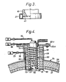
- the burner 10 can comprise an arrangement similar to that shown in Figure 2.
- manifold 37 can be provided with a plurality of discrete constricted openings 43.
- the latter as shown define a plurality of passages, each of which is communicated with the manifold chamber 37 to receive the pressurized fluid.
- the respective openings 43 are provided with a configuration such that the high velocity steam which leaves the respective openings is directed centrally toward the longitudinal axis of burner 10.
- Openings.43 can further be constructed as to provide the issuing steam with a particular configuration.
- the openings may be formed by replaceable nozzles in a wall of the manifold.
- the configuration can be substantially in the form of an fan-like flow to best provide the desired overlapping coverage across the face of burner 24.
- the plurality of streams will be directed substantially parallel to face 24 to form the barrier and achieve the above noted two functions, i.e. providing a shield, and also keeping the face clear of solid matter.
- the manifold can be provided with a single constricted opening as shown in Figure 2, or with a plurality of circularly arranged and spaced apart constricted openings as shown in Figure 3.
- the stream directing openings can be spaced downwardly from face 24 rather than positioned immediately contiguously therewith.
- the dynamic barrier or shield forming steam will be directed upwardly from the spaced apart openings and toward face 24.
- the focus of the steam jets in this instance witt be at the discharge lip 43. Fine particulate ash or slag will thereby be caught up into the steam jet and carried away from face 24. Further, any solid material that does engage or cling to lip 23 will be dislodged and swept away by the steam impinged thereagainst.
- a burner 50 is connected to a source of oxygen 51 and a source 52 of particulate hydrocarbon such as a coal slurry.
- the two components form a combustible mixture which, as it burns, forms products of combustion which are discharged into the reaction chamber 53 of a synthesis gas generator 54.
- the generator comprises a steel shell 56 constructed and lined with a refractory material 57 to withstand the harsh environment.
- the discharge end of burner 50 is positioned to introduce the resulting flame, as well as the products of combustion into chamber 53. In the latter, the hot products of the partial combustion are collected.
- the chamber 53 is provided with a neck 58 defining a refractory lined access opening 59, within which burner 10 is registered.
- the upper end of burner 50 is provided with a flange 52A which mates with a support flange 53A. The latter projects outwardly from neck 58 to hold the burner in place through bolts, and yet permit its ready removal for replacement or repair.
- Burner 50 comprises an elongate body 60 having a longitudinal passage terminating at a cylindrical opening 61 defined by a peripheral lip 62 at the burner face 63.
- a progressively narrowing wall 64 connects the passage with lip 62, to define a mixing compartment 65.
- the elongate passage through body 26 is provided with a conduit 66 disposed preferably coaxially thereof and having a discharge port 67 terminating at the mixing compartment 65.
- Conduit 66 defines an annular passage 68 between the conduit and the body 60. Annular passage 68 is communicated with source 52 of coal slurry by way of a valved conductor 69.
- the valve is operable to regulate the volume of particulate or finely ground coal mixture which is introduced from source 52 for combining with oxygen, to establish the desired combustible mixture in mixing compartment 65.
- the oxygen is introduced through conduit 66 by way of valved coolant 70.
- the lower face 63 of burner body 60 is exposed to the maximum temperature and the turbulent environment experienced within reaction chamber 53.
- the lower face 63 is normally formed of a heat resistant material such as Inconel. However, although capable of withstanding the elevated temperatures, face 63 is nonetheless susceptible to the herein noted particulate accumulations of slag.
- the latter is provided with one or more internal channels 72 arranged to circulate a coolant, preferably water.
- the cooling water channels are so arranged within burner body 60 to assure adequate heat removing capability thereby to stabilize the temperature within burner mixing compartment 65, and to protect the entire unit from excessive heating. Further cooling of the burner is achieved on body 60 by an externally positioned cooling coil 71 formed of a thermally conductive material.
- annular manifold 73 is provided.
- the manifold is disposed within reaction chamber 53 to cooperate with burner 50, and is communicated with a pressurized source 74 of fluid by way of pipe 76 and control valve 77.
- the torus-shaped, annular manifold 73 depends downwardly from generator shell 56 at the lower end of neck 58. Preferably, it extends inwardly to engage the burner face 63.
- Manifold 73 comprises a substantially closed annular chamber 78 which is formed of a series of welded plates or communicated compartments.
- the manifold can engage the lower end of burner 50, or it can be positioned sufficiently close thereto as to permit direction of the fluid flow which is projected transversely of the burner face 63.
- manifold 73 is provided with a single constricted opening 79 which communicates with fluid chamber 78 to direct a pressurized stream of fluid across the burner face 63.
- the fluid such as steam, preferably traverses burner face 63 in a substantially uninterrupted pattern.
- the stream will thus achieve at least two functions. Firstly, it will define a dynamic curtain or barrier across burner face 63. This will substantially preclude slag or ash particles from physically contacting the face. Secondly, the velocity of the steam jet or jets will be such as to dislodge any solid accumulation which might be initiated at lip 62. Thirdly, the disposition of the jet will be such as to afford a thermal radiation shield between face 63 and reaction chamber 53.
- the volume of steam which leaves constricted opening 79 is regulated to avoid adversely affecting production of the partially oxidized product in reaction chamber 53.
- Manifold 73 is suspended within the reaction chamber 53 to cooperate with the removable burner 10, and yet itself be removable from the generator 54.
- manifold 73 is removably fastened to a series of elongated support brackets 80.
- the latter are fastened to the neck 58, preferably behind the refractory brick layer which forms the inner wall of the neck.
- Said brackets 80 are so shaped to position burner 50 and also to maintain contact with the latter in spite of thermal expansion and contraction while operating.
- the brackets thus embody a transverse segment 81 that will permit the burner to expand downwardly against manifold 73 when the burner becomes heated.
- the fluid connection 76 which conducts steam into manifold 73 can also be disposed behind the refractory brick layer within the neck 58.
- the manifold 73 extends inwardly toward the discharge end of burner 50.
- the manifold upper side can be contoured or shaped that it slidably or abuttingly receives the lower edge of the burner 50.
- manifold support members 80, 81 can be conformed with neck 58 to permit the manifold to be displaced downwardly, and remain in contact with burner 10 when the latter is bolted into place at flange 53.
Landscapes
- Chemical & Material Sciences (AREA)
- Engineering & Computer Science (AREA)
- Combustion & Propulsion (AREA)
- Oil, Petroleum & Natural Gas (AREA)
- Organic Chemistry (AREA)
Claims (12)
Applications Claiming Priority (4)
| Application Number | Priority Date | Filing Date | Title |
|---|---|---|---|
| US407397 | 1982-08-12 | ||
| US407396 | 1982-08-12 | ||
| US06/407,396 US4527997A (en) | 1982-08-12 | 1982-08-12 | Coal gasification apparatus |
| US06/407,397 US4445444A (en) | 1982-08-12 | 1982-08-12 | Burner for combusting oxygen-coal mixture |
Publications (3)
| Publication Number | Publication Date |
|---|---|
| EP0101213A2 EP0101213A2 (fr) | 1984-02-22 |
| EP0101213A3 EP0101213A3 (en) | 1984-11-28 |
| EP0101213B1 true EP0101213B1 (fr) | 1987-09-30 |
Family
ID=27019874
Family Applications (1)
| Application Number | Title | Priority Date | Filing Date |
|---|---|---|---|
| EP19830304274 Expired EP0101213B1 (fr) | 1982-08-12 | 1983-07-22 | Brûleur et appareil pour la gazéification de charbon |
Country Status (3)
| Country | Link |
|---|---|
| EP (1) | EP0101213B1 (fr) |
| CA (1) | CA1207149A (fr) |
| DE (1) | DE3373915D1 (fr) |
Cited By (3)
| Publication number | Priority date | Publication date | Assignee | Title |
|---|---|---|---|---|
| US7488339B2 (en) | 2002-10-21 | 2009-02-10 | Boston Scientific Scimed, Inc. | Multilayer medical device |
| US7713047B2 (en) | 2003-01-27 | 2010-05-11 | Boston Scientific Scimed, Inc. | Extrusion apparatus for making multilayer articles |
| US7947059B2 (en) | 2000-03-02 | 2011-05-24 | Boston Scientific Scimed, Inc. | Multilayer medical device |
Families Citing this family (2)
| Publication number | Priority date | Publication date | Assignee | Title |
|---|---|---|---|---|
| DE4416037C1 (de) * | 1994-05-06 | 1995-09-07 | Noell Dbi Energie Entsorgung | Vorrichtung zum Verschluß einer Befahrungsöffnung und zur Brennerbefestigung für Druckvergasungsreaktoren |
| AU739352B2 (en) * | 1997-06-06 | 2001-10-11 | Texaco Development Corporation | Floating pressure gasifier feed injector cooling water system |
Family Cites Families (4)
| Publication number | Priority date | Publication date | Assignee | Title |
|---|---|---|---|---|
| DE968064C (de) * | 1952-01-23 | 1958-01-16 | Koppers Gmbh Heinrich | Verfahren und Vorrichtung zum Erzeugen wertvoller, Kohlenoxyd und Wasserstoff enthaltender Gase |
| FR1137874A (fr) * | 1954-11-13 | 1957-06-05 | Koppers Gmbh Heinrich | Dispositif de gazéification de combustibles finement divisés et en suspension |
| FR1442877A (fr) * | 1965-08-04 | 1966-06-17 | Urquhart S 1926 Ltd | Procédé et dispositif pour la production autothermique de combustibles gazeux |
| NL183096C (nl) * | 1979-06-13 | 1988-07-18 | Shell Int Research | Brander voor de partiele verbranding van een fijnverdeelde vaste brandstof met zuurstof en een moderatorgas. |
-
1983
- 1983-07-22 DE DE8383304274T patent/DE3373915D1/de not_active Expired
- 1983-07-22 EP EP19830304274 patent/EP0101213B1/fr not_active Expired
- 1983-07-27 CA CA000433379A patent/CA1207149A/fr not_active Expired
Cited By (4)
| Publication number | Priority date | Publication date | Assignee | Title |
|---|---|---|---|---|
| US7947059B2 (en) | 2000-03-02 | 2011-05-24 | Boston Scientific Scimed, Inc. | Multilayer medical device |
| US7488339B2 (en) | 2002-10-21 | 2009-02-10 | Boston Scientific Scimed, Inc. | Multilayer medical device |
| US7713047B2 (en) | 2003-01-27 | 2010-05-11 | Boston Scientific Scimed, Inc. | Extrusion apparatus for making multilayer articles |
| US8231374B2 (en) | 2003-01-27 | 2012-07-31 | Boston Scientific Scimed, Inc. | Extrusion apparatus for making multilayer articles |
Also Published As
| Publication number | Publication date |
|---|---|
| CA1207149A (fr) | 1986-07-08 |
| EP0101213A3 (en) | 1984-11-28 |
| DE3373915D1 (en) | 1987-11-05 |
| EP0101213A2 (fr) | 1984-02-22 |
Similar Documents
| Publication | Publication Date | Title |
|---|---|---|
| EP0973847B1 (fr) | Generateur de gaz de synthese comprenant des chambres de combustion et de refroidissement rapide | |
| SU839442A3 (ru) | Устройство дл газификации пылевидногоТОплиВА | |
| US4556384A (en) | Burner for pulverized coal | |
| JP4309257B2 (ja) | ガス吹き込みランス | |
| CN1255557C (zh) | 向冶金炉中喷吹气体的装置 | |
| JP4933442B2 (ja) | 燃料ガス化装置 | |
| US4157244A (en) | Gas-cooling method and apparatus | |
| US4527997A (en) | Coal gasification apparatus | |
| EP0730492B1 (fr) | Goulotte de gaseificateur | |
| US4445444A (en) | Burner for combusting oxygen-coal mixture | |
| EP0101213B1 (fr) | Brûleur et appareil pour la gazéification de charbon | |
| US5230868A (en) | Fluidized bed reactor with protected fluid distributor | |
| JPH0120206B2 (fr) | ||
| US5851497A (en) | Gasifier throat | |
| JP2020073674A (ja) | ガス化システム及びプロセス | |
| TWI390042B (zh) | 用以注入固態顆粒材料至一容器的裝置 | |
| EP0008847B2 (fr) | Installation de gazéification de charbon | |
| EP0078100B1 (fr) | Installation de gazéification de charbon | |
| US6422160B1 (en) | Apparatus for the combustion of vanadium-containing fuels | |
| EP0160424B1 (fr) | Assemblage d'un anneau de trempe et d'un tube d'immersion | |
| US3861859A (en) | Cooling of rotary furnace shell burner pipes and method | |
| US4195978A (en) | Coal gasification plant | |
| US5769035A (en) | Boiler furnace puff sootblower | |
| US3372917A (en) | Apparatus for recovery of converter off-gases | |
| US3912244A (en) | Apparatus for oxygen-lancing a metallurgical bath |
Legal Events
| Date | Code | Title | Description |
|---|---|---|---|
| PUAI | Public reference made under article 153(3) epc to a published international application that has entered the european phase |
Free format text: ORIGINAL CODE: 0009012 |
|
| AK | Designated contracting states |
Designated state(s): DE FR GB IT NL SE |
|
| PUAL | Search report despatched |
Free format text: ORIGINAL CODE: 0009013 |
|
| AK | Designated contracting states |
Designated state(s): DE FR GB IT NL SE |
|
| 17P | Request for examination filed |
Effective date: 19850520 |
|
| 17Q | First examination report despatched |
Effective date: 19860226 |
|
| GRAA | (expected) grant |
Free format text: ORIGINAL CODE: 0009210 |
|
| AK | Designated contracting states |
Kind code of ref document: B1 Designated state(s): DE FR GB IT NL SE |
|
| REF | Corresponds to: |
Ref document number: 3373915 Country of ref document: DE Date of ref document: 19871105 |
|
| ET | Fr: translation filed | ||
| ITF | It: translation for a ep patent filed | ||
| PLBE | No opposition filed within time limit |
Free format text: ORIGINAL CODE: 0009261 |
|
| STAA | Information on the status of an ep patent application or granted ep patent |
Free format text: STATUS: NO OPPOSITION FILED WITHIN TIME LIMIT |
|
| 26N | No opposition filed | ||
| ITTA | It: last paid annual fee | ||
| PGFP | Annual fee paid to national office [announced via postgrant information from national office to epo] |
Ref country code: FR Payment date: 19930608 Year of fee payment: 11 |
|
| PGFP | Annual fee paid to national office [announced via postgrant information from national office to epo] |
Ref country code: SE Payment date: 19930614 Year of fee payment: 11 |
|
| PGFP | Annual fee paid to national office [announced via postgrant information from national office to epo] |
Ref country code: GB Payment date: 19930621 Year of fee payment: 11 |
|
| PGFP | Annual fee paid to national office [announced via postgrant information from national office to epo] |
Ref country code: NL Payment date: 19930731 Year of fee payment: 11 |
|
| PGFP | Annual fee paid to national office [announced via postgrant information from national office to epo] |
Ref country code: DE Payment date: 19930930 Year of fee payment: 11 |
|
| PG25 | Lapsed in a contracting state [announced via postgrant information from national office to epo] |
Ref country code: GB Effective date: 19940722 |
|
| PG25 | Lapsed in a contracting state [announced via postgrant information from national office to epo] |
Ref country code: SE Effective date: 19940723 |
|
| EUG | Se: european patent has lapsed |
Ref document number: 83304274.0 Effective date: 19950210 |
|
| PG25 | Lapsed in a contracting state [announced via postgrant information from national office to epo] |
Ref country code: NL Effective date: 19950201 |
|
| NLV4 | Nl: lapsed or anulled due to non-payment of the annual fee | ||
| GBPC | Gb: european patent ceased through non-payment of renewal fee |
Effective date: 19940722 |
|
| PG25 | Lapsed in a contracting state [announced via postgrant information from national office to epo] |
Ref country code: FR Effective date: 19950331 |
|
| PG25 | Lapsed in a contracting state [announced via postgrant information from national office to epo] |
Ref country code: DE Effective date: 19950401 |
|
| EUG | Se: european patent has lapsed |
Ref document number: 83304274.0 |
|
| REG | Reference to a national code |
Ref country code: FR Ref legal event code: ST |