EP0101332B1 - Synchronisierungsanlage für ein elektronisches Zündsystem - Google Patents
Synchronisierungsanlage für ein elektronisches Zündsystem Download PDFInfo
- Publication number
- EP0101332B1 EP0101332B1 EP19830401213 EP83401213A EP0101332B1 EP 0101332 B1 EP0101332 B1 EP 0101332B1 EP 19830401213 EP19830401213 EP 19830401213 EP 83401213 A EP83401213 A EP 83401213A EP 0101332 B1 EP0101332 B1 EP 0101332B1
- Authority
- EP
- European Patent Office
- Prior art keywords
- signal
- ignition
- signals
- weights
- detectors
- Prior art date
- Legal status (The legal status is an assumption and is not a legal conclusion. Google has not performed a legal analysis and makes no representation as to the accuracy of the status listed.)
- Expired
Links
- 230000000630 rising effect Effects 0.000 claims description 13
- 230000002159 abnormal effect Effects 0.000 claims description 3
- 230000000903 blocking effect Effects 0.000 claims description 3
- 239000002184 metal Substances 0.000 claims description 3
- 238000002485 combustion reaction Methods 0.000 claims description 2
- 239000003999 initiator Substances 0.000 claims 1
- 238000010586 diagram Methods 0.000 description 13
- 230000001276 controlling effect Effects 0.000 description 2
- 125000004122 cyclic group Chemical group 0.000 description 2
- 230000007547 defect Effects 0.000 description 2
- 230000008034 disappearance Effects 0.000 description 2
- 230000000694 effects Effects 0.000 description 2
- 239000003990 capacitor Substances 0.000 description 1
- 239000000470 constituent Substances 0.000 description 1
- 238000001514 detection method Methods 0.000 description 1
- 238000001914 filtration Methods 0.000 description 1
- 230000005764 inhibitory process Effects 0.000 description 1
- 230000003071 parasitic effect Effects 0.000 description 1
- 230000001105 regulatory effect Effects 0.000 description 1
- 230000001360 synchronised effect Effects 0.000 description 1
- 230000001960 triggered effect Effects 0.000 description 1
Images





Classifications
-
- F—MECHANICAL ENGINEERING; LIGHTING; HEATING; WEAPONS; BLASTING
- F02—COMBUSTION ENGINES; HOT-GAS OR COMBUSTION-PRODUCT ENGINE PLANTS
- F02B—INTERNAL-COMBUSTION PISTON ENGINES; COMBUSTION ENGINES IN GENERAL
- F02B75/00—Other engines
- F02B75/16—Engines characterised by number of cylinders, e.g. single-cylinder engines
- F02B75/18—Multi-cylinder engines
- F02B75/22—Multi-cylinder engines with cylinders in V, fan, or star arrangement
-
- F—MECHANICAL ENGINEERING; LIGHTING; HEATING; WEAPONS; BLASTING
- F02—COMBUSTION ENGINES; HOT-GAS OR COMBUSTION-PRODUCT ENGINE PLANTS
- F02P—IGNITION, OTHER THAN COMPRESSION IGNITION, FOR INTERNAL-COMBUSTION ENGINES; TESTING OF IGNITION TIMING IN COMPRESSION-IGNITION ENGINES
- F02P3/00—Other installations
- F02P3/02—Other installations having inductive energy storage, e.g. arrangements of induction coils
- F02P3/04—Layout of circuits
- F02P3/055—Layout of circuits with protective means to prevent damage to the circuit, e.g. semiconductor devices or the ignition coil
- F02P3/0552—Opening or closing the primary coil circuit with semiconductor devices
- F02P3/0556—Protecting the coil when the engine is stopped
-
- F—MECHANICAL ENGINEERING; LIGHTING; HEATING; WEAPONS; BLASTING
- F02—COMBUSTION ENGINES; HOT-GAS OR COMBUSTION-PRODUCT ENGINE PLANTS
- F02P—IGNITION, OTHER THAN COMPRESSION IGNITION, FOR INTERNAL-COMBUSTION ENGINES; TESTING OF IGNITION TIMING IN COMPRESSION-IGNITION ENGINES
- F02P7/00—Arrangements of distributors, circuit-makers or -breakers, e.g. of distributor and circuit-breaker combinations or pick-up devices
- F02P7/06—Arrangements of distributors, circuit-makers or -breakers, e.g. of distributor and circuit-breaker combinations or pick-up devices of circuit-makers or -breakers, or pick-up devices adapted to sense particular points of the timing cycle
- F02P7/067—Electromagnetic pick-up devices, e.g. providing induced current in a coil
- F02P7/0675—Electromagnetic pick-up devices, e.g. providing induced current in a coil with variable reluctance, e.g. depending on the shape of a tooth
-
- F—MECHANICAL ENGINEERING; LIGHTING; HEATING; WEAPONS; BLASTING
- F02—COMBUSTION ENGINES; HOT-GAS OR COMBUSTION-PRODUCT ENGINE PLANTS
- F02B—INTERNAL-COMBUSTION PISTON ENGINES; COMBUSTION ENGINES IN GENERAL
- F02B75/00—Other engines
- F02B75/02—Engines characterised by their cycles, e.g. six-stroke
- F02B2075/022—Engines characterised by their cycles, e.g. six-stroke having less than six strokes per cycle
- F02B2075/027—Engines characterised by their cycles, e.g. six-stroke having less than six strokes per cycle four
-
- F—MECHANICAL ENGINEERING; LIGHTING; HEATING; WEAPONS; BLASTING
- F02—COMBUSTION ENGINES; HOT-GAS OR COMBUSTION-PRODUCT ENGINE PLANTS
- F02B—INTERNAL-COMBUSTION PISTON ENGINES; COMBUSTION ENGINES IN GENERAL
- F02B75/00—Other engines
- F02B75/16—Engines characterised by number of cylinders, e.g. single-cylinder engines
- F02B75/18—Multi-cylinder engines
- F02B2075/1804—Number of cylinders
- F02B2075/1848—Number of cylinders twelve
Definitions
- the invention relates to a synchronization device for an electronic ignition system intended for a multi-cylinder internal combustion engine and more particularly to a 4-stroke gas engine.
- a device of this type is known from French patent 7,827,923.
- this known device as many weights are provided as there are spark generators and at least one auxiliary weights angularly offset with respect to one of the main weights, at an angle equal to the angular spacing of the detectors.
- This provision is necessary when using dual-channel automatic advance circuits or the spacing of the detectors must be at least equal to the maximum advance angle of the motor but less than the angle separating the point of ignition of two successive cylinders.
- the number of weights for one engine revolution is equal to the number minus one of cylinders to be ignited during this engine revolution and that the angular spacing of the detectors is such that for each ignition point minus two of the same engine revolution the detectors are simultaneously energized while only one detector is energized for the other two ignition points and the electronic means include a coincidence circuit which receives the two signals E1 and E2 and supplies the signal SO when these signals are in different logic states and one of the signals E1 or E2 is in a predetermined logic state, and a logic circuit providing the signal S1 when at least one of the signals E1 or E2 is delivered by the detectors.
- a device applies to an ignition system comprising n generators each paired with 2 cylinders set at 360 ° to a 2n cylinder engine.
- the disc on which n - 1 weights are placed is driven directly by the crankshaft, it can however be driven by the camshaft and then have 2n - 2 weights.
- the reference signals SO and S1 can be used to control a device for sequential and cyclic distribution of the triggering signals of the spark generators comprising a programmable counter whose number of states is equal to the number of spark generators, such as example as that described in French patent 7,638,128.
- the signal S0 is not disturbed by defects in form and synchronization or by the accidental absence of one of the signals from the detectors.
- the coincidence circuit comprises means generating from the signal E1 two signals A and B, the rising edge of which coincides with the rising edge of E1 and of lengths such that B ⁇ A ⁇ E1, means supplying a pulse C including the rising edge corresponding to the falling edge of B and the falling edge to the falling edge of A, means delivering an inverse signal E2 of E2, a logic operator of type ET delivering the reference signal SO when the pulse C is in the same logic state as signal E2.
- a safety device which blocks the ignition in the event of an abnormal absence of one of these signals.
- This safety device comprising two programmable counters, one counting the pulses E1, the other the pulses E2, both reset to 0 by the reference signal SO and logic means delivering a safety signal which blocks ignition if the SO signal appears while the count is less than the normal number of pulses E1 or E2: this is explained below.
- a particularly reliable synchronization device is thus obtained which does not require great precision in the positioning of the counterweights and the detectors.
- the embodiment which will be described applies to a 12-cylinder V-shaped engine with successive ignition points of the cylinders equidistant or not.
- the invention can of course be applied to an engine with N cylinders, N being a number greater than two, even or odd.
- Each spark generator is coupled to two cylinders whose ignition point is' phase shifted by 360 ° crankshaft.
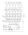
- the entire device is shown diagrammatically in FIG. 1.
- Six spark generators 21 to 26 each distribute the ignition energy simultaneously to a cylinder in the first row of cylinders (numbered 1 to 6) and to a cylinder in the second row of cylinders (numbered 7 to 12) .
- the distribution block 50 cyclically triggers the spark generators in order 21 to 26 and it can be seen by the connections to the cylinders that the ignition order carried out is 1-8-5-10-3-7-6- 11-2-9-4-12.
- the distribution block 50 prepares the triggering orders for the spark generators as a function essentially of a synchronization signal SO supplied by a synchronization signal generator 52 and a progress signal S1 supplied by a control block and trigger 53.
- the signals SO and S1 are produced from signals E1 and E2 delivered cyclically during each engine cycle by an adapter 51, an engine cycle corresponding to the sequential ignition of all the engine cylinders.
- the distribution block 50 is shown in detail in Fig. 2-11 comprises a programmable counter 100 whose reset reset input receives the synchronization signal SO and the count input C the progress signal S1.
- the counter 100 has six counting outputs (numbered 1 to 6) each connected respectively to an input of the six NAND gates 101 to 106 and a seventh output 7 looped through to the reset reset input.
- the other inputs of the doors 101 to 106 receive from the control and trigger block 53 a so-called energy-controlled EC signal.
- the outputs of doors 101 and 106 are each connected respectively to an input of NOR gates 111 to 116, the other input of which can receive an ignition inhibition IA signal from safety block 55.
- the cyclic distribution is correctly ensured if a signal S1 is supplied to the counter at each change to the top dead center of a cylinder and a synchronization signal SO of initialization for each engine revolution to the counter 100 (eg the cylinders 1 to 6).
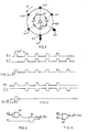
- Fig. 3 shows the electromechanical means developing them. They comprise a disc 60 integral in rotation with the engine shaft or crankshaft 59 which rotates in the opposite direction to the needles. of a watch.
- the disc 60 carries at its periphery 5 identical conductive metal weights m1 to m5 spaced consecutively by a constant angle (60 ° in the example), the weights m5 and m1 being spaced twice this angle.
- two fixed detectors 61, 62 Next to these weights are arranged two fixed detectors 61, 62.
- the constituent circuits of the detectors can for example be of the type described in the French patent 7638128 mentioned above.
- the detectors 61, 62 respectively send signals E1, E2 of logic level 1.
- the setting of the detectors is such that the signal E1 corresponds each time to a top dead center.
- the timing diagrams of the signals E1, E2, SO and S1 are shown in FIG. 4.
- a coincidence circuit receives the two signals E1 and E2 and supplies the signal SO when E1 and E2 are in logic state 1 and a logic circuit (Fig. 6) supplies the signal S1 when at least one of the signals E1 or E2 is in logic state 1.
- the coincidence circuit comprises an AND gate 63 and an inverter 64.
- the logic circuit 65 consists of an OR gate.
- the sensor described in FIG. 3 applies to an engine with equidistant ignition points (case of a 12 cylinders in V at 60 °).
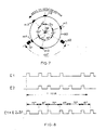
- the ignition points are not equidistant, they are alternately spaced by 75 ° and 45 °.
- the usual means of adapting and filtering the signals have not been shown.
- a sensor of this configuration is shown in FIG. 7 and the corresponding timing diagrams in FIG. 8.
- Figures 9 to 11 show the disturbances of the synchronization signal S0 due to improper calibration and / or poor relative positioning of the signals E1 and E2.
- the appearance of parasitic SO signals may disturb the order in which the cylinders are ignited and thus cause serious engine damage.
- Fig. 9 represents the case where the radial distances of the detectors with respect to the weights are unequal
- FIG. 10 the case where the angle between the detectors is not equal to the angle between two weights having to simultaneously excite them
- FIG. 11 the general case of a detection imprecision leading to a deviation of the rising or falling edges of two pulses E1, E2 simultaneous.
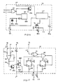
- the synchronization signal generator 52 (Fig. 12) comprises a first monostable circuit conventionally constituted by two NAND gates 66 and 67, the capacitor C1 and the resistor R1. This monostable receives the signal E1 and delivers the signal To. A second monostable (68, 69, C2, R2) delivers the signal B. The duration of the signals A and B is respectively regulated by the choice of C1 R1 and C2R2. A NAND gate 70 whose inputs receive the signals A and B delivers the pulse C. A NAND gate 71 whose inputs receive the signal E2 and the pulse C delivers the signal ⁇ . Finally, an AND gate 72 delivers the signal SO from the pulses C and D. The signals S0, C and D are delivered respectively to terminals 73, 74 and 75.
- the device functions correctly if the detectors 61, 62 indeed supply a signal E1 or E2 when each counterweight passes. If an E1 or E2 signal is absent due to the failure of a detector, an excess SO signal or no SO signal is obtained during a cycle, as the case may be (Fig. 14 and 15). This leads to a shift in the distribution of sparks which can cause serious engine damage.
- the operational amplifier 76 receives from the control and trigger block 53 a TV voltage as a function of the speed of the motor.
- the output of the operational amplifier 76 is connected to the base of a transistor T1 of the NPN type, the emitter of which is connected to ground and the collector connected to the base of a transistor T2 of the NPN type.
- the base of the transistor T2 is connected to the power supply by a resistor R7, its emitter to ground and its collector on the one hand to the power supply via a resistor R10 and on the other hand to the inputs R of the two flip-flops 77 and 78 RS type (for example a 4013) by resistors R8 and R9.
- the input S of the flip-flop 77 receives the synchronization signal SO coming from the output 73 of the synchronization signal generator 52.
- the output to of the flip-flop 77 is connected to one of the inputs of the NOR logic gate 80 , the other input of which is connected to an inverter 79 which receives the signal D taken at the output 75 of the signal generator 52.
- the output of the gate 80 is connected to the input S of the flip-flop 78 whose output Q delivers the ignition prohibition signal IA which is applied to an input of each of the doors 111 to 116 (FIG. 2) of the distribution block 50.
- the base of the transistor T2 receives the safety signal SC coming from the sensor safety block 54.
- the purpose of the safety block 55 is to prohibit ignition until a first synchronization signal SO has not appeared since the counter 100 is then not synchronized. As long as the TV signal arriving at the operational amplifier 76 is not of a sufficient level to make the transistors T1 and T2 pass, a level 1 is applied to the inputs R of the flip-flops 77 and 78 which remain insensitive to the signals that they receive. The output to flip-flop 78 then delivers a signal IA of level 1 which, applied to doors 111 to 116 prohibits ignition.
- the inputs R of flip-flops 77 and 78 receive a signal 0. This allows flip-flop 77 to switch in the presence of the first signal S0 applied to its input S and rocker 78 to switch in the presence of the first signal D arriving by the inverter 79.
- the flip-flops 77 and 78 are used in the same way to prevent ignition when a level 1 safety signal SC from the sensor safety block 54 is applied to the base of transistor T2.
- this safety block comprises two programmable counters 81 and 82 counting one the pulses E1, the other the pulses E2, the one and the other reset to 0 by the synchronization signal SO and logic means delivering the safety signal SC which blocks the ignition if the signal SO appears while the count is less than the normal number of pulses E1 or E2.
- the counting input C of the counter 81 receives the signals E1 coming from the synchronization signal generator 52 and corresponding to the calibrated signal E1.
- the counting input C of the counter 82 receives the signals E2 coming from the sensor 51.
- the counters are reset by loopback and sends the synchronization signal SO to their inputs RZ as described for the counter 100 (doors CU N ° 01, 02, 03, 04).
- the logic means comprise a first group of two flip-flops RS 83 and 84 testing the outputs A1 and D1 of the counter 81 and a second group of flip-flops RS 85 to 89 testing the outputs B2 to F2 of the counter 82.
- the R and S inputs of flip-flops 83 to 89 are connected to the outputs of the counters 81 to 82 as shown in FIG. 18.
- the Q outputs of flip-flops 83 and 84 are connected to the two inputs of a NOR gate 90 and the Q outputs of flip-flops 85 to 89 to the five inputs of a NAND gate 91 which can be produced by a circuit of the type 4068 from MOTOROLA.
- the output of the NOR gate 90 is connected to the input S of a flip-flop D 92 and the output of the NAND gate 91 to the input S of a second flip-flop D 93 through the inverter circuit 91a .
- the outputs Q of flip-flops 92 and 93 control via the transistors T3 and T4 the cut-off signal SC delivered to the output 94 of the sensor safety block 54.
- the output of the NAND gate 91 switches to state 0 which brings after inversion by the circuit 91a the input S of the flip-flop 93 to state 1 and as before the signal SC takes the value 0 which causes the blocking of the safety block 55. It will be noted that the condition is possible thanks to the fact that the rising edge of signal C is used as the end of state 0 of outputs 0 of flip-flops 85 to 89, while the start of state 0 of the next flip-flop is triggered by the rising edge of corresponding signal E2 which is ahead of the rising edge of C.
- control and trigger block 53 shown diagrammatically in FIG. 16.
- the circuit 97 receives via the transistor T7 a trigger signal at each appearance of a signal E1 or E2 and the signal-voltage TV as a function of the speed delivered by the circuit 96. It delivers at its output 98a the so-called energy signal EC controlled applied to the inputs of doors 101 to 106 of the distribution block 50 and to its output 98b via the transistor T6 the signal S1 applied to the input C of the counter 100.
- the TV signal used by the security block 55 is taken from terminal 99.
Landscapes
- Engineering & Computer Science (AREA)
- Chemical & Material Sciences (AREA)
- Combustion & Propulsion (AREA)
- Mechanical Engineering (AREA)
- General Engineering & Computer Science (AREA)
- Physics & Mathematics (AREA)
- Electromagnetism (AREA)
- Ignition Installations For Internal Combustion Engines (AREA)
Claims (6)
Applications Claiming Priority (2)
| Application Number | Priority Date | Filing Date | Title |
|---|---|---|---|
| FR8213195A FR2531146B1 (fr) | 1982-07-28 | 1982-07-28 | Dispositif de synchronisation pour un systeme d'allumage electronique |
| FR8213195 | 1982-07-28 |
Publications (2)
| Publication Number | Publication Date |
|---|---|
| EP0101332A1 EP0101332A1 (de) | 1984-02-22 |
| EP0101332B1 true EP0101332B1 (de) | 1987-01-21 |
Family
ID=9276415
Family Applications (1)
| Application Number | Title | Priority Date | Filing Date |
|---|---|---|---|
| EP19830401213 Expired EP0101332B1 (de) | 1982-07-28 | 1983-06-14 | Synchronisierungsanlage für ein elektronisches Zündsystem |
Country Status (3)
| Country | Link |
|---|---|
| EP (1) | EP0101332B1 (de) |
| DE (1) | DE3369364D1 (de) |
| FR (1) | FR2531146B1 (de) |
Families Citing this family (3)
| Publication number | Priority date | Publication date | Assignee | Title |
|---|---|---|---|---|
| DE3602292A1 (de) * | 1986-01-25 | 1987-08-06 | Audi Ag | Geberanordnung |
| WO1993009393A1 (en) * | 1991-11-06 | 1993-05-13 | Orbital Engine Company (Australia) Pty. Limited | Method and apparatus for determining position of a body in cyclic movement |
| RU2209996C1 (ru) * | 2001-12-18 | 2003-08-10 | Открытое акционерное общество "Чебоксарское научно-производственное приборостроительное предприятие "ЭЛАРА" | Устройство для системы зажигания двигателя внутреннего сгорания |
Family Cites Families (4)
| Publication number | Priority date | Publication date | Assignee | Title |
|---|---|---|---|---|
| DE2541594C3 (de) * | 1975-09-18 | 1978-09-07 | Robert Bosch Gmbh, 7000 Stuttgart | Vorrichtung zur Ruhestromabschaltung bei einer für Brennkraftmaschinen bestimmten Zündanlage |
| JPS5826339Y2 (ja) * | 1977-07-20 | 1983-06-07 | 株式会社デンソー | 回転基準位置検出装置 |
| DE2802582A1 (de) * | 1978-01-21 | 1979-07-26 | Bbc Brown Boveri & Cie | Elektronischer drehwinkelgeber |
| FR2446467A1 (fr) * | 1979-01-09 | 1980-08-08 | Renault | Procede et appareillage de reperage de la position angulaire d'une piece animee d'un mouvement de rotation |
-
1982
- 1982-07-28 FR FR8213195A patent/FR2531146B1/fr not_active Expired
-
1983
- 1983-06-14 EP EP19830401213 patent/EP0101332B1/de not_active Expired
- 1983-06-14 DE DE8383401213T patent/DE3369364D1/de not_active Expired
Also Published As
| Publication number | Publication date |
|---|---|
| FR2531146B1 (fr) | 1986-05-16 |
| FR2531146A1 (fr) | 1984-02-03 |
| DE3369364D1 (en) | 1987-02-26 |
| EP0101332A1 (de) | 1984-02-22 |
Similar Documents
| Publication | Publication Date | Title |
|---|---|---|
| CA1100174A (fr) | Systeme d'allumage electronique et moteur a combustion interne equipe d'un tel systeme | |
| EP0013846B1 (de) | Verfahren und Vorrichtung zur Bestimmung der Winkellage eines rotierenden Teiles | |
| US4378004A (en) | Engine control system with cylinder identification apparatus | |
| US4145608A (en) | Rotational reference position detecting apparatus | |
| EP0181379A1 (de) | Pulsierungsdetektor für fehlende oder zusätliche pulsierungen. | |
| EP0006367B1 (de) | Auslösungseinrichtung, insbesondere für die Zündung einer Brennkraftmaschine | |
| EP0010033B1 (de) | Winkelgeber für Brennkraftmaschine mit einer elektronischen Zündanlage | |
| CH625596A5 (de) | ||
| FR2867560A1 (fr) | Procede et dispositif pour determiner la position angulaire du vilebrequin d'un moteur a combustion interne | |
| FR2541456A1 (fr) | Dispositif pour afficher et/ou memoriser des defauts de dispositifs indicateurs sur des moteurs a combustion interne | |
| EP0101332B1 (de) | Synchronisierungsanlage für ein elektronisches Zündsystem | |
| FR2524566A1 (fr) | Dispositif de reglage de l'allumage pour moteurs a combustion interne | |
| FR2478398A1 (fr) | Controle numerique de la vitesse d'un moteur | |
| EP0032333B1 (de) | Vorrichtung zur Erkennung von Verbrennungsstörungen in einem Explosionsmotor | |
| JPH11132089A (ja) | 内燃機関のスタートの際の所定のシリンダーの燃焼サイクルの検知のための方法及び装置 | |
| JPH04219468A (ja) | 内燃機関の点火装置 | |
| CH645161A5 (fr) | Procede et dispositif de commande automatique d'un circuit d'allumage d'un moteur a combustion interne. | |
| JP2541597B2 (ja) | 内燃機関の制御のための装置 | |
| EP0029374A1 (de) | Signal-generator zur Korrektur der Einstellung der Frühzündung in Abhängigkeit vom Klopfverhalten | |
| JPH0267463A (ja) | スパーク・タイミング制御装置及び方法 | |
| FR2566839A1 (fr) | Capteur destine a detecter le passage d'un piston ou groupe de pistons d'un moteur a combustion interne par la position du point mort haut | |
| EP0033280A2 (de) | Steuerungsvorrichtung für die Zündspule eines Verbrennungsmotors mit einem elektronischen Rechner zur Zündverstellung | |
| FR2467301A1 (fr) | Systeme d'allumage de moteurs a combustion interne | |
| SU1324119A1 (ru) | Устройство дл автоматического пуска и остановки электродвигател телеграфного аппарата | |
| JP3329639B2 (ja) | 点火制御バックアップ装置 |
Legal Events
| Date | Code | Title | Description |
|---|---|---|---|
| PUAI | Public reference made under article 153(3) epc to a published international application that has entered the european phase |
Free format text: ORIGINAL CODE: 0009012 |
|
| AK | Designated contracting states |
Designated state(s): DE GB IT |
|
| 17P | Request for examination filed |
Effective date: 19840419 |
|
| 17Q | First examination report despatched |
Effective date: 19860702 |
|
| GRAA | (expected) grant |
Free format text: ORIGINAL CODE: 0009210 |
|
| AK | Designated contracting states |
Kind code of ref document: B1 Designated state(s): DE GB IT |
|
| ITF | It: translation for a ep patent filed | ||
| REF | Corresponds to: |
Ref document number: 3369364 Country of ref document: DE Date of ref document: 19870226 |
|
| PLBE | No opposition filed within time limit |
Free format text: ORIGINAL CODE: 0009261 |
|
| STAA | Information on the status of an ep patent application or granted ep patent |
Free format text: STATUS: NO OPPOSITION FILED WITHIN TIME LIMIT |
|
| 26N | No opposition filed | ||
| PGFP | Annual fee paid to national office [announced via postgrant information from national office to epo] |
Ref country code: GB Payment date: 19910611 Year of fee payment: 9 |
|
| PGFP | Annual fee paid to national office [announced via postgrant information from national office to epo] |
Ref country code: DE Payment date: 19910628 Year of fee payment: 9 |
|
| ITTA | It: last paid annual fee | ||
| PG25 | Lapsed in a contracting state [announced via postgrant information from national office to epo] |
Ref country code: GB Effective date: 19920614 |
|
| GBPC | Gb: european patent ceased through non-payment of renewal fee |
Effective date: 19920614 |
|
| PG25 | Lapsed in a contracting state [announced via postgrant information from national office to epo] |
Ref country code: DE Effective date: 19930302 |