EP0101336A2 - Generator zur Verarbeitung eines Videosignals mit Kontrast für Strahlenkunde und Verfahren für derartige Signalverarbeitung - Google Patents
Generator zur Verarbeitung eines Videosignals mit Kontrast für Strahlenkunde und Verfahren für derartige Signalverarbeitung Download PDFInfo
- Publication number
- EP0101336A2 EP0101336A2 EP83401286A EP83401286A EP0101336A2 EP 0101336 A2 EP0101336 A2 EP 0101336A2 EP 83401286 A EP83401286 A EP 83401286A EP 83401286 A EP83401286 A EP 83401286A EP 0101336 A2 EP0101336 A2 EP 0101336A2
- Authority
- EP
- European Patent Office
- Prior art keywords
- frame
- point
- values
- value
- points
- Prior art date
- Legal status (The legal status is an assumption and is not a legal conclusion. Google has not performed a legal analysis and makes no representation as to the accuracy of the status listed.)
- Granted
Links
Images


Classifications
-
- G—PHYSICS
- G06—COMPUTING OR CALCULATING; COUNTING
- G06T—IMAGE DATA PROCESSING OR GENERATION, IN GENERAL
- G06T5/00—Image enhancement or restoration
- G06T5/50—Image enhancement or restoration using two or more images, e.g. averaging or subtraction
-
- H—ELECTRICITY
- H04—ELECTRIC COMMUNICATION TECHNIQUE
- H04N—PICTORIAL COMMUNICATION, e.g. TELEVISION
- H04N23/00—Cameras or camera modules comprising electronic image sensors; Control thereof
- H04N23/30—Cameras or camera modules comprising electronic image sensors; Control thereof for generating image signals from X-rays
Definitions
- the invention relates to an apparatus for generating a processed contrast-enhanced video signal for producing radiographic images and, more particularly, to an apparatus and method for obtaining improved images of an opacified anatomy at using a fluoroscopic type device combined with a video processor.
- a typical X-ray fluoroscopy apparatus includes an X-ray source and an image intensifier used to detect X-rays.
- the output of the image enhancer is recorded by a television camera and the resulting television signal can be sent on a monitor and / or recorded.
- a body such as that of a patient
- these rays are absorbed to different degrees, depending on the thickness and composition of the different parts of the body.
- the resulting representation is a two-dimensional image which can be used, for example for the diagnosis of certain structural anomalies inside the body.
- X-ray contrast agents are used to create a large difference in X-ray absorption behavior when there was none or almost none before.
- blood vessels are virtually invisible on fluoroscopic images (with the exception of the thorax) since the behavior of X-rays in the blood, muscles, fatty and soft tissue is similar.
- Radiographic contrast agents contain materials (air, barium, iodine for example) whose absorption properties of X-rays are different from those of blood, muscles, fatty or soft tissue.
- a dose of iodized liquid contrast agent is injected into an artery or vein, the vascular structure receives artificially enhanced contrast on an x-ray image as long as the contrast agent persists in a certain vascular segment.
- the so-called mask display mode is a direct form of subtraction display, as a function of time, supplemented by digital processing.
- a patient is placed on an x-ray table and one chooses the area of interest in order to examine it, for example the carotid or the cardiac cavity.
- a simple digital image is formed on several video frames (essentially between one and four) which are recorded in a digital memory.
- the opacifier is then rapidly injected (for example between 3 and 5 seconds); it goes into the right part of the heart cavity, then in the lungs and finally in the left part of the cavity from where it is pumped into the arterial system of the human body.
- a sequence of additional images is stored in a second digital memory.
- Each of these post-opacification images is subtracted in the order of the image memorized before the injection.
- the subtraction images thus formed were synthesized at the rate of approximately one image / second so as to obtain relatively fixed arterial structures. For fast cardiac structures, this rate has been increased between 15 and 60 images / second approximately.
- the time-dependent subtraction images thus formed should ideally display only the clouded cardiovascular anatomy.
- the image contrast due to the non-opacified anatomy such as that of the bones for example, is suppressed.
- the removal of foreign image information improves the contrast of opacified structures.
- the subtraction images are reconverted into video format and then stored, for example on tape or videotape. Full treatment and external storage can be done in real time while the patient is on the table.
- serial number 342,376, assigned to the same assignee as that of the present application there is disclosed a technique by which recursive filtering is used to filter the video signals from radiography with a filtering function whose temporal frequency essentially corresponds to the expected temporal frequency of the movement of the opacifying dose in the region of the body viewed.
- the video image thus treated tends to improve the parts of the image where the opacifier has circulated while attenuating the role of the fixed tissues and those moving at a temporal speed notably higher than that of the peak of the bandwidth.
- the technique described above can be considered as a retrospective filtering which rejects most of the data (for example video frames other than those which are the subject of the subtraction).
- the recursive filtering technique in question also chooses a characteristic of the filter prospectively, the choice of the filter being based on a priori hypotheses as to the shape of the dilution curve of the opacifier.
- the techniques of the prior art represent compromises.
- the present invention essentially uses all the data acquired and also includes retrospective knowledge of the real visualization characteristics of the region of the body concerned during the passage of the opacifier dose.
- an apparatus and a method for forming a processed video signal representative of an image of a body A source of radiation can be directed onto the body and devices are provided to detect radiation received from the body and convert that detected radiation to an electronic video signal. Devices are provided for storing a series of frames of the video signal in the form of digital point values. These digital point values are generally representative of the radiation absorption characteristic of the part of the human body corresponding to the position of the elementary points of the frame, although it is understood that other characteristics, such as transmission, may be treated according to these same principles when necessary.
- a device is provided for determining for each frame, i, of the series a corresponding average point value Si of the frame.
- Means have also been provided for determining for each frame, i, of the series, an improvement value (or filter coefficient), ki, as a function of Si.
- This improvement value ki is preferably determined as the difference of Si and 5, where S is the mean of Si over the frame sequence.
- the improvement value Ki can be either positive or negative.
- Other devices have also been applied to combine the values of the points of each of the stored frames, i, with the improvement value ki of the frame, so as to obtain improved point values.
- Means are also provided for combining the improved values of the corresponding points of the frames of the sequence in order to obtain a processed value for each point location. These processed values can be converted into analog form for viewing.
- the absorption densities used to determine ki for each frame 1 are obtained in a predetermined part of the frame defined by the surface of a window. If one chooses the surface of the window so as to include most or all of the region of the body concerned that the dose of contrasting product will cross during the sequence of the frame treated, limiting the determination of ki to apply the value of the points in the window, the selective filter characteristic obtained will provide a better "adaptation" to the temporal response of the dose than if we considered the entire area of the frame for this determination.
- the technique of the present invention provided an improvement in the signal / noise ratio which made it possible, in comparison with the techniques of the prior art, very significant reductions in the dose of contrasting product necessary to obtain an image of given quality.
- FIG. 1 illustrates a simplified diagram of an apparatus 100 giving a visualized image of the internal structure of the body 20.
- the apparatus 100 comprises, conventionally, a source of radiation 100, essentially consisting of a source X-ray, a detector 120 and a video generator 130.
- the combination of the detector and the video generator may include, for example, an X-ray image enhancer as well as a television camera.
- the output of the video generator 130 is coupled to a video recorder 150 as well as to an analog-to-digital converter 151 which converts the television signal into a digital signal.
- the output of the recorder 150 is also coupled to the converter 151.
- the equipment necessary to obtain a digital television signal is well known in this sector of the art and exists commercially; as an example we can cite the model AD-96A310 manufactured by THOMSON-CSF Broadcast, Inc.
- the television signal converter At each point of the frame, the television signal converter generates an eight-bit digital signal representing 256 graduations of the luminance level (for a monochrome signal, as seen in the embodiment presently illustrated).
- the video recorder 150 can be constituted by any type of suitable recording device, video recorder or recorder on discs.
- the video generator, the video recorder and the analog-digital converter conventionally receive synchronization signals and the analog-digital converter also receives clock signals at the rate of the points.
- the output of the analog-digital converter 151 is coupled to the processing circuitry 200 which may include a general type digital computer, a microprocessor or special digital electronics. Analog converter output digital logic 151 is also coupled to an arithmetic accumulator 160 which, for its part, is controlled by the processor 200 with which it communicates. The video generator 130 and the video recorder 150 are also controlled by the processor 200. This may include, for example, a model 68000 microprocessor manufactured by Motorola Corporation or a version called a "slice microprocessor" thereof.
- the output of the digital-analog converter 151 is also coupled to a multiplier circuit 170 controlled by the processor 200.
- the output of the multiplier circuit is coupled to another accumulator 300 which includes a frame memory 305 and a totalization circuit 306.
- the output of the accumulator 300 is coupled to a digital-analog converter 195 whose output is coupled. on the screen 198 and on a video recorder, which may be constituted by the recorder 150. It is also assumed that the vertical and horizontal concordance signals, as well as the clock signals, are supplied in a conventional manner by the generation circuitry, synchronization and clock, not shown.
- any type of time filtering scheme can be represented in the frequency domain by its associated time frequency response (amplitude and phase) or in the time domain by its impulse response.
- the filter output, s' (t) is given by: where denotes convolution.
- the signal consists of a clearance of discrete samples of s (t), distributed over T seconds, the output of the filter is a discrete sum given by: where s [i] is the i-th sample of s (t) and f [i], the i-th sample of f (t).
- the nth output is: or : or :
- equation (4) ' is a weighted sum of all the input samples, ending at the N-th sample.
- the l-th sample is chosen near the maximum clouding time and the m-th sample at a time corresponding to a weak clouding.
- the other N-2 samples are rejected.
- the present filtering method which essentially uses all the acquired data and which incorporates a retrospective knowledge of (s [j] has the advantages of these two visualization approaches. If we consider the set of samples (s [j]) , the choice of k j can be done so as to optimize according to a chosen criterion. If we choose
- the signal (S) and noise (n) associated with a single point are expressed as follows in this filtering technique: where ⁇ is the standard deviation of the noise per point, in the case of each sample. Equation (7) assumes that the noise of the sample ( ⁇ ) is uncorrelated, from one sample to another and that ⁇ is independent of j. In order to ensure that the fixed bottom anatomy is canceled on the N-th exit, we impose the condition:
- equation (6) can be rewritten as follows: where c is an arbitrary constant. S / n is maximized by setting: By replacing equations (7) and (8) in (9) and solving k ; we get the following expression: and equation 10 can be rewritten as follows: where a ([k j ]) is a proportionality constant which depends on [k j ]:
- Equation (17) we can evaluate S / n from equations (7) and (8), as follows: or : and one evaluates (s [i] - s) eff only for the samples used for filtering.
- the quantity N + 1 is the number of input samples retained for processing.
- FIG. 2 is a basic flowchart which, when taken in conjunction with the corresponding flowcharts, shows how the processing circuit 200 is programmed to control the operation of the circuit of Figure 1 in the present embodiment.
- Block 201 represents the determination of the mean point value Si for each frame i.
- the routine of this operation called "pass I" is represented in FIG. 3.
- After having obtained the value S i of each frame of the sequence we take the average of the values S i as represented by block 202, in order to obtain an overall average value, designated by S.
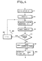
- the routine of this operation is shown in FIG. 4.
- an improvement value k is obtained. compatible with the relation (17) above, as shown in block 203.
- the pass II is applied when for each frame 1 of the sequence, the value of each point is multiplied by k i .
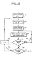
- the routine of this operation is illustrated in FIG. 5.
- the values of the improved points of each frame of the sequence are stored in the accumulator 300 (FIG. 1) and compatible with the relation (4) ' above.
- the new accumulated value is then restored to the position of the particular point of the frame memory 305.
- the memory 305 stores the desired value of the accumulated points, at each point location.
- FIG. 3 illustrates the pass routine which makes it possible to obtain the value Si of each frame i of the sequence.
- Block 211 represents the selection made by the operator of the window surface.
- the window defines the area in which the average point value, general Si of the present embodiment, is obtained.
- the operator can choose the window surface by moving, for example, a classic cursor point to the diagonally opposite angles of the window and by entering the coordinates of these angles. Alternatively, the coordinates of the angles of the surface can be entered conventionally using a keyboard.
- the operator can also enter the number of frames in the sequence to be processed (block 212).
- the accumulator 160 (FIG. 1) is reset to zero and the frame number 1 is initialized in one block (213).
- Block 214 represents the input of the following display frame of the generator 150, via the analog / digital converter 151.
- the loop 220 is then introduced. This represents the application of the procedure which gives the value Si frame average i.
- the values of the individual points are read from the analog-digital converter 151 (block 215).
- the line or elementary point number, as the case may be, is increased (block 216). It is determined (diamond 217) whether or not the current point is within the predetermined window area. In the affirmative, block 218 is introduced. This block represents an increase in the totalized figure in the accumulator of the value of the current point. If not, block 218 is skipped. The determination is then made (diamond 221) if the last point of the window has been processed.
- loop 220 is maintained until frame i is finished. Since, in this embodiment, only the points in the window enter the determination of Si, it is not necessary to continue examining the points once the point of the window located at the part lower right has been reached.
- the value of Si is then stored in combination with the frame index 1 (block 222).
- the accumulator is then reset to zero (block 223) and then it is determined (diamond 224) whether the last frame of the sequence has been processed or not. If not, the loop 230 continues by increasing the frame number (block 235) and entering the block 214. The loop 230 is maintained until all the values Si of the sequence of frames have been determined and stored.
- the flow diagram of FIG. 4 represents the routine of block 202 of FIG. 2 where the individual values Si are averaged to obtain S.
- the initialized frame number (block 411) and a variable SBAR, used for the accumulation of values Si is initialized to zero (block 412).
- the stored value Si associated with i is set up (block 413).
- SBAR is then increased by the value If set up, as represented by block 414.
- We then ask (Decision, diamond 415) if we have reached the last frame in the series. If not, the frame number is increased (block 416) and the loop 410 is maintained until all the values Si have been added to SBAR.
- Block 421 is then introduced. This represents the division of the sum SBAR by the number of frames in the series in order to obtain S, a value which is then stored (block 422).
- the flow diagram of FIG. 5 is a representation of the pass routine I of block 204 of FIG. 2 where, for each frame i of the sequence, the value of each point is multiplied by ki and the improved value of the point is added to the value of the corresponding points of the other frames of the sequence by the accumulator 300 (FIG. 1).
- the frame index is initialized (block 511) and the improvement value ki is output to the multiplier 170 (block 512).
- the raster dots 1 of the sequence are entered into the multiplier 170 (block 513), one after the other (block 514), from the analog / digital converter 151.
- the loop 520 is maintained until the last point of the grid has been processed (diamond 515).
- a determination is then made (diamond 525) to find out whether the last frame of the sequence has been processed or not. If not, the frame index is increased by one (block 526) and loop 530 is held until all the frames in the sequence have been processed.
Landscapes
- Engineering & Computer Science (AREA)
- Physics & Mathematics (AREA)
- General Physics & Mathematics (AREA)
- Theoretical Computer Science (AREA)
- Multimedia (AREA)
- Signal Processing (AREA)
- Apparatus For Radiation Diagnosis (AREA)
- Image Processing (AREA)
- Analysing Materials By The Use Of Radiation (AREA)
- Closed-Circuit Television Systems (AREA)
Applications Claiming Priority (2)
| Application Number | Priority Date | Filing Date | Title |
|---|---|---|---|
| US06/390,512 US4456926A (en) | 1982-06-21 | 1982-06-21 | Enhancement of fluroscopically generated images |
| US390512 | 1982-06-21 |
Publications (3)
| Publication Number | Publication Date |
|---|---|
| EP0101336A2 true EP0101336A2 (de) | 1984-02-22 |
| EP0101336A3 EP0101336A3 (en) | 1985-11-06 |
| EP0101336B1 EP0101336B1 (de) | 1989-08-02 |
Family
ID=23542763
Family Applications (1)
| Application Number | Title | Priority Date | Filing Date |
|---|---|---|---|
| EP83401286A Expired EP0101336B1 (de) | 1982-06-21 | 1983-06-21 | Generator zur Verarbeitung eines Videosignals mit Kontrast für Strahlenkunde und Verfahren für derartige Signalverarbeitung |
Country Status (5)
| Country | Link |
|---|---|
| US (1) | US4456926A (de) |
| EP (1) | EP0101336B1 (de) |
| JP (1) | JPS5940836A (de) |
| CA (1) | CA1205213A (de) |
| DE (1) | DE3380324D1 (de) |
Cited By (2)
| Publication number | Priority date | Publication date | Assignee | Title |
|---|---|---|---|---|
| FR2555003A1 (fr) * | 1983-11-13 | 1985-05-17 | Elscint Ltd | Procede et systeme d'amelioration du contraste d'une image |
| CN113689342A (zh) * | 2020-05-18 | 2021-11-23 | 上海联影医疗科技股份有限公司 | 一种图像质量优化的方法及系统 |
Families Citing this family (11)
| Publication number | Priority date | Publication date | Assignee | Title |
|---|---|---|---|---|
| US4792854A (en) * | 1982-09-14 | 1988-12-20 | New York Institute Of Technology | Apparatus for temporally processing a video signal |
| US4542459A (en) * | 1982-11-26 | 1985-09-17 | General Electric Company | Matched filter for x-ray hybrid subtraction |
| JPS59103648A (ja) * | 1982-12-06 | 1984-06-15 | 株式会社東芝 | X線撮像装置 |
| NL8801982A (nl) * | 1988-08-09 | 1990-03-01 | Philips Nv | Werkwijze en inrichting voor het bepalen van grootheden die kenmerkend zijn voor de stroming van een vloeistof in een vatenstelsel. |
| DE19625727C2 (de) * | 1996-06-27 | 2000-11-09 | Bernd Porr | Einrichtung zur Bestimmung der Disparität in einem Stereobildpaar |
| US6226350B1 (en) * | 1998-12-31 | 2001-05-01 | General Electric Company | Methods and apparatus for cardiac scoring with a multi-beam scanner |
| EP1090306A1 (de) * | 1999-04-20 | 2001-04-11 | Koninklijke Philips Electronics N.V. | Bildverarbeitungsmethode |
| US6256368B1 (en) * | 1999-10-15 | 2001-07-03 | General Electric Company | Methods and apparatus for scout-based cardiac calcification scoring |
| DE10238322A1 (de) * | 2002-08-21 | 2004-03-11 | Siemens Ag | Retrospektive bzw. fenstergesteuerte Filterung von Bildern zur Adaption von Schärfe und Rauschen in der Computer-Tomographie |
| DE10345073A1 (de) * | 2003-09-26 | 2005-05-04 | Siemens Ag | Betriebsverfahren für ein tomographiefähiges bildgebendes Untersuchungsgeräts und Röntgen-Computertomographiegerät |
| FR2884340B1 (fr) * | 2005-04-11 | 2012-03-02 | Gen Electric | Procede et dispositif de traitement d'images en angiographie soustraite |
-
1982
- 1982-06-21 US US06/390,512 patent/US4456926A/en not_active Expired - Fee Related
-
1983
- 1983-06-20 CA CA000430739A patent/CA1205213A/en not_active Expired
- 1983-06-21 JP JP58110285A patent/JPS5940836A/ja active Granted
- 1983-06-21 EP EP83401286A patent/EP0101336B1/de not_active Expired
- 1983-06-21 DE DE8383401286T patent/DE3380324D1/de not_active Expired
Non-Patent Citations (2)
| Title |
|---|
| IBM JOURNAL OF RESEARCH AND DEVELOPMENT, vol. 17, no. 3, mai 1973, pages 206-218, New York, US; C.K. CHOW et al.: "X-ray image subtraction by digital means" * |
| JOURNAL OF NUCLEAR MEDICINE, vol. 11, no. 11, novembre 1970, pages 680-688, New York, US; W.L. ASHBURN et al.: "Digital and analog processing of anger camera data with a dedicated computer-controlled system" * |
Cited By (3)
| Publication number | Priority date | Publication date | Assignee | Title |
|---|---|---|---|---|
| FR2555003A1 (fr) * | 1983-11-13 | 1985-05-17 | Elscint Ltd | Procede et systeme d'amelioration du contraste d'une image |
| CN113689342A (zh) * | 2020-05-18 | 2021-11-23 | 上海联影医疗科技股份有限公司 | 一种图像质量优化的方法及系统 |
| CN113689342B (zh) * | 2020-05-18 | 2024-04-02 | 上海联影医疗科技股份有限公司 | 一种图像质量优化的方法及系统 |
Also Published As
| Publication number | Publication date |
|---|---|
| JPS5940836A (ja) | 1984-03-06 |
| EP0101336A3 (en) | 1985-11-06 |
| US4456926A (en) | 1984-06-26 |
| CA1205213A (en) | 1986-05-27 |
| DE3380324D1 (en) | 1989-09-07 |
| JPH0434867B2 (de) | 1992-06-09 |
| EP0101336B1 (de) | 1989-08-02 |
Similar Documents
| Publication | Publication Date | Title |
|---|---|---|
| EP0113605B1 (de) | Verfahren und Einrichtung zur Erzeugung eines Körperröntgenbildes | |
| EP0101336B1 (de) | Generator zur Verarbeitung eines Videosignals mit Kontrast für Strahlenkunde und Verfahren für derartige Signalverarbeitung | |
| FR2505168A1 (fr) | Appareil et procede pour produire une image projetee d'une matiere de contraste administree dans une region du corps | |
| JPS59229670A (ja) | 空間分散フイルタを用いる多重測定雑音低減装置 | |
| FR2632427A1 (fr) | Procede pour ameliorer sensiblement le temps de reconstruction d'une image dans une tomographie informatisee a angle limite | |
| FR2779853A1 (fr) | Procede de reconstruction d'une image tridimensionnelle d'un objet, en particulier une image tridimensionnelle angiographique | |
| FR2602602A1 (fr) | Dispositif et procede de correction d'image vue a vue pour le mouvement d'un objet | |
| FR2741723A1 (fr) | Systeme elabore de medecine nucleaire | |
| FR2550037A1 (fr) | Correction de defauts de cadrage automatique | |
| FR2662813A1 (fr) | Procede d'acquisition d'images d'echographie. | |
| FR2498442A1 (fr) | Procede et appareil de radioscopie | |
| JP2001238870A (ja) | 器官の厚みを補償する方法および装置 | |
| JPS58109032A (ja) | 身体映像装置 | |
| FR2812741A1 (fr) | Procede et dispositif de reconstruction d'une image tridimensionnelle dynamique d'un objet parcouru par un produit de contraste | |
| FR2736181A1 (fr) | Procede de traitement d'images pour la reduction du bruit dans une image d'une sequence d'images numeriques et dispositif mettant en oeuvre ce procede | |
| EP0110787B1 (de) | Verfahren und Gerät zur Formung von Schnittbildern eines Körpers | |
| FR2482396A1 (fr) | Installation de radiodiagnostic pour l'etablissement d'images soustractrices | |
| BE897048A (fr) | Procede et dispositif pour le traitement d'images radioscopiques | |
| EP0037722A1 (de) | Verfahren und Vorrichtung für das dynamische Hervorheben von Abbildungen | |
| EP0674185A1 (de) | Verfahren und Vorrichtung zum Detektieren und Charakterisieren eines Abschnitts eines Blutgefässes mit Ultraschall-Echographie | |
| EP0055655B1 (de) | Verfahren und Vorrichtung, um mittels einer einstellbaren Strahlungsquelle einen beleuchteten Körper optisch darzustellen | |
| FR2814666A1 (fr) | Procede et appareil d'examen d'un sein par injection d'un produit de contraste | |
| FR2884341A1 (fr) | Procede et systeme d'amelioration d'une image digitale generee a partir d'un detecteur de rayons x | |
| FR2799029A1 (fr) | Procede de reconstruction d'une image tridimensionnelle d'un objet en mouvement, en particulier une image tridimensionnelle de vaisseaux du coeur humain | |
| EP3654847B1 (de) | Verfahren zur charakterisierung von knochen mittels ultraschallwellen |
Legal Events
| Date | Code | Title | Description |
|---|---|---|---|
| PUAI | Public reference made under article 153(3) epc to a published international application that has entered the european phase |
Free format text: ORIGINAL CODE: 0009012 |
|
| AK | Designated contracting states |
Designated state(s): DE FR GB IT NL |
|
| PUAL | Search report despatched |
Free format text: ORIGINAL CODE: 0009013 |
|
| AK | Designated contracting states |
Designated state(s): DE FR GB IT NL |
|
| 17P | Request for examination filed |
Effective date: 19851115 |
|
| 17Q | First examination report despatched |
Effective date: 19870126 |
|
| RAP3 | Party data changed (applicant data changed or rights of an application transferred) |
Owner name: THOMSON-CSF |
|
| GRAA | (expected) grant |
Free format text: ORIGINAL CODE: 0009210 |
|
| AK | Designated contracting states |
Kind code of ref document: B1 Designated state(s): DE FR GB IT NL |
|
| ITF | It: translation for a ep patent filed | ||
| GBT | Gb: translation of ep patent filed (gb section 77(6)(a)/1977) | ||
| REF | Corresponds to: |
Ref document number: 3380324 Country of ref document: DE Date of ref document: 19890907 |
|
| PLBE | No opposition filed within time limit |
Free format text: ORIGINAL CODE: 0009261 |
|
| STAA | Information on the status of an ep patent application or granted ep patent |
Free format text: STATUS: NO OPPOSITION FILED WITHIN TIME LIMIT |
|
| PGFP | Annual fee paid to national office [announced via postgrant information from national office to epo] |
Ref country code: GB Payment date: 19900604 Year of fee payment: 8 |
|
| ITTA | It: last paid annual fee | ||
| 26N | No opposition filed | ||
| PG25 | Lapsed in a contracting state [announced via postgrant information from national office to epo] |
Ref country code: GB Effective date: 19910621 |
|
| GBPC | Gb: european patent ceased through non-payment of renewal fee | ||
| PGFP | Annual fee paid to national office [announced via postgrant information from national office to epo] |
Ref country code: DE Payment date: 19920526 Year of fee payment: 10 |
|
| PGFP | Annual fee paid to national office [announced via postgrant information from national office to epo] |
Ref country code: NL Payment date: 19920630 Year of fee payment: 10 |
|
| PG25 | Lapsed in a contracting state [announced via postgrant information from national office to epo] |
Ref country code: NL Effective date: 19940101 |
|
| NLV4 | Nl: lapsed or anulled due to non-payment of the annual fee | ||
| PG25 | Lapsed in a contracting state [announced via postgrant information from national office to epo] |
Ref country code: DE Effective date: 19940301 |
|
| PGFP | Annual fee paid to national office [announced via postgrant information from national office to epo] |
Ref country code: FR Payment date: 20020530 Year of fee payment: 20 |