EP0101340B1 - Matériaux composites et gaines de garnissage intérieur pour conduites réalisées en ces matériaux - Google Patents
Matériaux composites et gaines de garnissage intérieur pour conduites réalisées en ces matériaux Download PDFInfo
- Publication number
- EP0101340B1 EP0101340B1 EP19830401351 EP83401351A EP0101340B1 EP 0101340 B1 EP0101340 B1 EP 0101340B1 EP 19830401351 EP19830401351 EP 19830401351 EP 83401351 A EP83401351 A EP 83401351A EP 0101340 B1 EP0101340 B1 EP 0101340B1
- Authority
- EP
- European Patent Office
- Prior art keywords
- pipe
- sheath
- layer
- reinforcement
- woven fabric
- Prior art date
- Legal status (The legal status is an assumption and is not a legal conclusion. Google has not performed a legal analysis and makes no representation as to the accuracy of the status listed.)
- Expired
Links
- 239000000463 material Substances 0.000 title claims description 53
- 239000002131 composite material Substances 0.000 title claims description 17
- 239000004745 nonwoven fabric Substances 0.000 claims description 36
- 230000002787 reinforcement Effects 0.000 claims description 31
- 239000000853 adhesive Substances 0.000 claims description 28
- 230000001070 adhesive effect Effects 0.000 claims description 28
- 239000011347 resin Substances 0.000 claims description 11
- 229920005989 resin Polymers 0.000 claims description 11
- 238000000034 method Methods 0.000 claims description 9
- 229920001187 thermosetting polymer Polymers 0.000 claims description 7
- 239000004744 fabric Substances 0.000 claims description 5
- 229920002994 synthetic fiber Polymers 0.000 claims description 4
- 230000000063 preceeding effect Effects 0.000 claims 3
- 239000011888 foil Substances 0.000 claims 1
- 239000010410 layer Substances 0.000 description 57
- 239000003365 glass fiber Substances 0.000 description 10
- 238000004519 manufacturing process Methods 0.000 description 9
- 239000002759 woven fabric Substances 0.000 description 5
- 239000000835 fiber Substances 0.000 description 4
- 239000011521 glass Substances 0.000 description 4
- 229920000728 polyester Polymers 0.000 description 4
- 239000004698 Polyethylene Substances 0.000 description 3
- 239000012530 fluid Substances 0.000 description 3
- -1 polyethylene Polymers 0.000 description 3
- 229920000573 polyethylene Polymers 0.000 description 3
- 229920000915 polyvinyl chloride Polymers 0.000 description 3
- 239000004800 polyvinyl chloride Substances 0.000 description 3
- 230000008569 process Effects 0.000 description 3
- 238000003466 welding Methods 0.000 description 3
- 230000002745 absorbent Effects 0.000 description 2
- 239000002250 absorbent Substances 0.000 description 2
- 230000000712 assembly Effects 0.000 description 2
- 238000000429 assembly Methods 0.000 description 2
- 238000003490 calendering Methods 0.000 description 2
- 238000009434 installation Methods 0.000 description 2
- 230000003014 reinforcing effect Effects 0.000 description 2
- 229920000742 Cotton Polymers 0.000 description 1
- 230000009471 action Effects 0.000 description 1
- 125000000484 butyl group Chemical group [H]C([*])([H])C([H])([H])C([H])([H])C([H])([H])[H] 0.000 description 1
- 239000011248 coating agent Substances 0.000 description 1
- 238000000576 coating method Methods 0.000 description 1
- 238000010276 construction Methods 0.000 description 1
- 230000007797 corrosion Effects 0.000 description 1
- 238000005260 corrosion Methods 0.000 description 1
- 238000005336 cracking Methods 0.000 description 1
- 230000003628 erosive effect Effects 0.000 description 1
- 238000009963 fulling Methods 0.000 description 1
- 238000010438 heat treatment Methods 0.000 description 1
- 239000007788 liquid Substances 0.000 description 1
- 239000012528 membrane Substances 0.000 description 1
- 230000004048 modification Effects 0.000 description 1
- 238000012986 modification Methods 0.000 description 1
- 229920003023 plastic Polymers 0.000 description 1
- 239000004033 plastic Substances 0.000 description 1
- 230000001681 protective effect Effects 0.000 description 1
- 230000009467 reduction Effects 0.000 description 1
- 238000009958 sewing Methods 0.000 description 1
- 239000002356 single layer Substances 0.000 description 1
- 238000005507 spraying Methods 0.000 description 1
- 239000012209 synthetic fiber Substances 0.000 description 1
- 125000000391 vinyl group Chemical group [H]C([*])=C([H])[H] 0.000 description 1
- 229920002554 vinyl polymer Polymers 0.000 description 1
- 210000002268 wool Anatomy 0.000 description 1
Images


Classifications
-
- F—MECHANICAL ENGINEERING; LIGHTING; HEATING; WEAPONS; BLASTING
- F16—ENGINEERING ELEMENTS AND UNITS; GENERAL MEASURES FOR PRODUCING AND MAINTAINING EFFECTIVE FUNCTIONING OF MACHINES OR INSTALLATIONS; THERMAL INSULATION IN GENERAL
- F16L—PIPES; JOINTS OR FITTINGS FOR PIPES; SUPPORTS FOR PIPES, CABLES OR PROTECTIVE TUBING; MEANS FOR THERMAL INSULATION IN GENERAL
- F16L55/00—Devices or appurtenances for use in, or in connection with, pipes or pipe systems
- F16L55/16—Devices for covering leaks in pipes or hoses, e.g. hose-menders
- F16L55/162—Devices for covering leaks in pipes or hoses, e.g. hose-menders from inside the pipe
-
- B—PERFORMING OPERATIONS; TRANSPORTING
- B32—LAYERED PRODUCTS
- B32B—LAYERED PRODUCTS, i.e. PRODUCTS BUILT-UP OF STRATA OF FLAT OR NON-FLAT, e.g. CELLULAR OR HONEYCOMB, FORM
- B32B5/00—Layered products characterised by the non- homogeneity or physical structure, i.e. comprising a fibrous, filamentary, particulate or foam layer; Layered products characterised by having a layer differing constitutionally or physically in different parts
- B32B5/02—Layered products characterised by the non- homogeneity or physical structure, i.e. comprising a fibrous, filamentary, particulate or foam layer; Layered products characterised by having a layer differing constitutionally or physically in different parts characterised by structural features of a fibrous or filamentary layer
- B32B5/10—Layered products characterised by the non- homogeneity or physical structure, i.e. comprising a fibrous, filamentary, particulate or foam layer; Layered products characterised by having a layer differing constitutionally or physically in different parts characterised by structural features of a fibrous or filamentary layer characterised by a fibrous or filamentary layer reinforced with filaments
-
- B—PERFORMING OPERATIONS; TRANSPORTING
- B32—LAYERED PRODUCTS
- B32B—LAYERED PRODUCTS, i.e. PRODUCTS BUILT-UP OF STRATA OF FLAT OR NON-FLAT, e.g. CELLULAR OR HONEYCOMB, FORM
- B32B5/00—Layered products characterised by the non- homogeneity or physical structure, i.e. comprising a fibrous, filamentary, particulate or foam layer; Layered products characterised by having a layer differing constitutionally or physically in different parts
- B32B5/22—Layered products characterised by the non- homogeneity or physical structure, i.e. comprising a fibrous, filamentary, particulate or foam layer; Layered products characterised by having a layer differing constitutionally or physically in different parts characterised by the presence of two or more layers which are next to each other and are fibrous, filamentary, formed of particles or foamed
- B32B5/24—Layered products characterised by the non- homogeneity or physical structure, i.e. comprising a fibrous, filamentary, particulate or foam layer; Layered products characterised by having a layer differing constitutionally or physically in different parts characterised by the presence of two or more layers which are next to each other and are fibrous, filamentary, formed of particles or foamed one layer being a fibrous or filamentary layer
- B32B5/26—Layered products characterised by the non- homogeneity or physical structure, i.e. comprising a fibrous, filamentary, particulate or foam layer; Layered products characterised by having a layer differing constitutionally or physically in different parts characterised by the presence of two or more layers which are next to each other and are fibrous, filamentary, formed of particles or foamed one layer being a fibrous or filamentary layer another layer next to it also being fibrous or filamentary
-
- F—MECHANICAL ENGINEERING; LIGHTING; HEATING; WEAPONS; BLASTING
- F16—ENGINEERING ELEMENTS AND UNITS; GENERAL MEASURES FOR PRODUCING AND MAINTAINING EFFECTIVE FUNCTIONING OF MACHINES OR INSTALLATIONS; THERMAL INSULATION IN GENERAL
- F16L—PIPES; JOINTS OR FITTINGS FOR PIPES; SUPPORTS FOR PIPES, CABLES OR PROTECTIVE TUBING; MEANS FOR THERMAL INSULATION IN GENERAL
- F16L55/00—Devices or appurtenances for use in, or in connection with, pipes or pipe systems
- F16L55/16—Devices for covering leaks in pipes or hoses, e.g. hose-menders
- F16L55/162—Devices for covering leaks in pipes or hoses, e.g. hose-menders from inside the pipe
- F16L55/165—Devices for covering leaks in pipes or hoses, e.g. hose-menders from inside the pipe a pipe or flexible liner being inserted in the damaged section
- F16L55/1656—Devices for covering leaks in pipes or hoses, e.g. hose-menders from inside the pipe a pipe or flexible liner being inserted in the damaged section materials for flexible liners
Definitions
- the present invention relates to a flexible integral composite material constituted by at least one assembly comprising a layer of nonwoven fabric and a flexible reinforcement disposed under said nonwoven fabric, which can in particular be used for the production of internal lining sheaths for damaged pipes, by example.
- This invention also relates to a sleeving sheath and to a method of lining the interior of a pipe by means of a sheath made of said composite material.
- a flexible integral composite material is known for the manufacture of wool felt hats from French patent 664 743 which comprises, interposed in the thickness of the felt, a “network” of woven fabric, this network being able to be assimilated to a frame.
- the material described in this French patent therefore comprises a felt layer and a frame embedded in the thickness of this layer, the outer and inner faces of this material always being those of a felt, even if several assemblies are assembled.
- the material, according to this French patent is shaped by fulling only.
- this composite material must, in order to be able to be used for a pipe lining sheath, include an outer layer or the like capable of absorbing an adhesive, the outside face of this layer being applied against the inside face of the pipe up to hardening of this adhesive; the pipe then being provided with a protective sheath.
- the thickness of the sheath necessarily increasing as a function of the section of the pipe to be filled, the thickness of the external absorbent layer also increases and, consequently, the quantity of adhesive to be supplied to ensure the adhesion of the sheath to the pipe increases not only as a function of the external surface of the sheath (therefore of the section of the pipe), but also, in a disproportionate manner, as a function of the thickness of the layer absorbing the adhesive of the sheath.
- the sheath becomes excessively heavy, the pressures for applying the sheath against the pipe become increasingly high, which makes it very difficult to introduce the sheath into the pipe, its application against the inner face of the pipe and maintaining the application pressure until the adhesive hardens.
- the cost of the equipment and the filling operation becomes excessive.
- the integral flexible composite material constituted by at least one assembly comprising a layer of nonwoven fabric and a flexible reinforcement disposed under said nonwoven fabric is characterized in that a second nonwoven fabric is disposed on the underside of said frame of the last assembly and in that a flexible and waterproof sheet having a substantially smooth outer face is fixedly connected to the underside of said second nonwoven fabric.
- Said first nonwoven fabric may be the same as said second nonwoven fabric.
- Nonwoven fabrics can be made of natural or synthetic fibers.
- the frame can be made in the form of a non-woven fabric or a mesh.
- the warp of said mesh may have dimensions greater than those of the weft.
- the present invention also relates to the inner sleeving sheaths of a pipe made with a flexible integral composite material as described above.
- the invention relates to a method of lining the interior of a pipe produced with a sheath as specified above, characterized in that the interior face of the pipe and / or the second layer provided with a coating is coated. reinforcement with an adhesive material, such as a thermosetting resin; in that one applies, thereafter, the sheath against the inner face of the pipe by exerting a pressure on the inner face of the sheath while possibly increasing the temperature inside the sheath until hardening of the adhesive and in that the said pressure for applying the sheath to the pipe is then reduced.
- an adhesive material such as a thermosetting resin
- the material (10) shown in Figure 1 comprises at least one assembly comprising a first layer (1) of a nonwoven fabric, such as natural or artificial felt.
- this layer (1) is made of polyester fibers.
- This layer (1) is followed by at least one flexible and resistant reinforcement (2), for example in glass fiber fabric or in a glass fiber mesh.
- reinforcements (2) can be placed one on the other: for example, a fabric reinforcement can be combined with a reinforcement having the configuration of a mesh, etc. If the material comprises only one together (1, 2), a layer (3) of a nonwoven fabric is fixedly connected to the underside of the layer (2) comprising at least one frame.
- the thickness (e l ) of the layer (1) can, in this case, be equal to that (e 3 ) of the layer (3); however, this is not compulsory: the thicknesses (e i ) and (e 3 ) can be chosen so as to allow the most advantageous production of a material (10) for the execution of a sheath (G i ) for example.
- the thickness (e i ) of the layer comprising at least one reinforcement is chosen as a function of the number of reinforcements used and of the flexibility and the mechanical resistance which it is desired to impart to the material (10) to be used. to make a sheath (G i ).
- the material (10) can comprise several assemblies: layer of nonwoven fabric - layer of reinforcements.
- the example shown in Figure 1 has two sets: layer (1, 2) and layers (3, 4); however, the last layer (5) is preferably made of a nonwoven fabric; it is fixedly connected to the lower part of the last layer comprising at least one reinforcement.
- the thicknesses of the layers of nonwoven fabric (e i ), (e 3 ), (e s ) and the thicknesses of the layers - reinforcements (e 2 ), (e4) are chosen so as to confer the best possible qualities for the constitution. a sheath (G i ), for example.
- G i a sheath
- All the layers (1, 2, 3, 4, 5) are permeable to an adhesive such as a thermosetting resin.
- These qualities allow the advantageous use of this material (10) for the production of sheaths (G i ) of interior lining for pipes.
- a sheet of the material (10) is rolled to form a tubular element whose outside diameter (D) is slightly smaller than the inside diameter of the pipe.
- the ends (10 1. 10 2 ) of the sheet produced in the material (10) form a lap joint, which facilitates the determination of the diameter (D) most advantageous for the introduction of the sheath (G i ) into the pipe (See Fig. 3).
- the sheath is coated with the adhesive which penetrates all the layers of the material (10).
- the ends (10 1 , 10 2 ) of the sheet can then slide relative to each other as long as the adhesive remains liquid.
- a bag or the like having at least the length of the sheath.
- This bag is made of a sheet of polyethylene, polyvinyl chloride or the like. This sheet cannot therefore adhere to the sheath by the action of the adhesive.
- the bag is inflated; the temperature is possibly increased.
- the sheet of polyethylene, polyvinyl chloride or the like is then applied firmly against the underside of the sheath (layer 3 or layer 5) and the sheath (G i ) is applied firmly against the interior face of the pipe.
- the adhesive cannot flow on the underside of the sheath (layer 3 or layer 5) and the latter remains smooth and airtight after the adhesive has hardened and after the bag will have been deflated and removed.
- the diameter (D) of the sheath (G i ) increases without the material (10) being subjected to forces. This is made possible by sliding the ends (10 1 ), (10 2 ) of the lap joint relative to each other before the adhesive has hardened.
- the material (10) impregnated with hard polymerized resin allows the constitution of a sheath (G i ) light, resistant and tight and whose interior face is smooth.
- the material (11) shown in Figure 2 is similar to that shown in Figure 1 except that it comprises as a lower layer a flexible and waterproof sheet (6) fixedly connected to the layer (5) of nonwoven fabric.
- This sheet (6) can be made of polyethylene, polyvinyl chloride, etc., as is already known from patent application No. 8,200,933 of January 21, 1982, in the name of the applicant.
- This material (11) can be used to constitute sheaths (G 2 ) of interior lining for pipes (C) (see FIG. 4). At least one of the ends of the sheath (G 2 ) is extended in the bottom of the well (P) for access to the ground pipe (S) so as to exceed the end of the pipe (C).
- the edges of the end of the sheath (G 2 ) are then pressed against each other and joined by welding, for example.
- the tightness of the sheath (G 2 ) at one of its ends is thus ensured.
- the layers (1, 2, 3, 4, 5) of the material (11) constituting the sheath (G 1 ) are impregnated with an adhesive such as a thermosetting resin.
- the adhesive cannot penetrate into the layer (6), nor pass through the layer (6).
- the sheath (G 2 ) thus being prepared and introduced into the pipe (C), a pressurized and possibly heated fluid acts directly or indirectly on the inner face of the sheath (G 2 ). This is applied firmly by its outer face to the inner face of the pipe (C) until the adhesive hardens.
- the part of the sheath (G 2 ), the edges of which are welded, which exceeds the end of the pipe (C) is cut flush with the wall (20) of the well (P), for example.
- the sheath (G 2 )
- Figure 4 shows, in section, an embodiment of the material according to the invention
- Figure 5 shows, in perspective, on a larger scale, an embodiment of a reinforcing reinforcement of the material to the invention.
- the material (M) shown in FIG. 5 has a thickness equal to (e) and comprises a first layer (100) which may consist of a flexible and waterproof sheet of a natural or synthetic material, such as rubber, butyl, polychloride vinyl, plyethylene, etc., the thickness of the layer (100) is equal to (e 20 ).
- this sheet (100) constitutes the inner layer of the composite material; its free underside is therefore preferably smooth in order to reduce, as much as possible, the friction between the fluid flowing in the duct and the lining.
- a second layer (110) having a thickness (e io ) is fixed on the first layer (100).
- This second layer (110) consists of a natural or synthetic felt provided with a flexible frame (120) disposed substantially at mid-thickness ( 010/2 ) of this layer.
- the felt is made up of cotton fibers, for example, or preferably, polyester fibers which are, for example, flocked or applied under hot pressure (by calendering for example) on the upper face of the sheet (or layer) (100), the reinforcement (120) being put in place prior to flocking or hot calendering, for example.
- the method of manufacturing the material (M) not forming part of the invention is not described.
- This felt is intended to absorb and retain an adhesive during the pressure application of the lining sheath against the interior face of the pipe; it is, in the context of the invention, that the adhesive can be applied to the layer (110), to the inner face of the pipe or to both (layer and pipe).
- the frame (120) is preferably, but not exclusively, constituted by a grid made of glass fibers, for example.
- the grid shown in Figure 6 has chains (122) and wefts (121) arranged perpendicular to each other.
- the chains (122) can have dimensions larger than those of the frames (121), for example.
- the chains (122) are arranged in the direction of the longitudinal axis of the sheath. But it is also possible to drown the reinforcement (120) in the layer (110) so that, during the manufacture of the material (M), the wefts (121) are arranged in the direction of the longitudinal axis of the sheath formed in said material (M).
- the chains (122) and wefts (121) of the frame (120) can be arranged diagonally with respect to the longitudinal axis of the sheath.
- the reinforcement (120) gives increased resistance to all of the material (M) whose total thickness (e) will only vary in comparatively small proportions as a function of the increase in diameter (or section) of the pipe to be provided with an inner lining sheath formed in said material (M). Also, the amount of adhesive will only increase by a comparatively small amount, since the thickness (e 10 ) of the layer (110) will only increase slightly. The total weight of the lining sheath comprising the adhesive always remains comparatively low; consequently, the pressure necessary to apply the sheath against the inner face of the pipe increases only slightly as a function of the diameters (or of the section) of the pipe.
- the consumption of adhesive is lower than in known methods; and the quantity of material (M) is less than that necessary in processes practiced until now.
- the equipment to create the pressure to apply the sheath against the pipe and to apply the adhesive may be lighter than that used on existing construction sites. There is therefore a gain in energy, in the quantity of materials, and a reduction in the cost of the process.
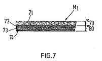
- the material (M i ), according to said fourth embodiment, shown in Figure 7 comprises a first layer (e io ) in a first non-woven fabric (71), such as a felt, for example.
- This nonwoven fabric (71) can be made of polyester fibers, for example; but other natural or artificial fibers can be used.
- This layer (e 70 ) is followed by at least a second layer (e ao ) comprising a first frame (72), a second nonwoven fabric (73) and a second frame (74).
- the first frame (72) and / or the second frame (74) are made of a woven fabric or a glass fiber mesh; said second nonwoven fabric disposed between the two frames (72) and (74) is advantageously made of glass fibers or glass mat.
- the thickness of the layer (e 7o ) in a first nonwoven fabric (71) is, in general, greater than the thickness of each of the reinforcements (72, 74) and of the nonwoven fabric (73) in glass mat ; the thicknesses of the reinforcements (72, 74) can be equal or different; in general, the thickness of each of the frames (72, 74) is greater than or at most equal to the thickness of the nonwoven fabric (73) made of glass mat.
- the material (M i ) can be constituted solely by the layer (e ao ) comprising said first reinforcement (72), a nonwoven fabric (73) and a second reinforcement (74) (not shown in the drawings).
- the reinforcements (72, 74) are made, for example, of a woven fabric of glass fibers and the non-woven fabric woven (73) of glass fiber or glass mat.
- the thicknesses of the reinforcements (72, 74) and of the nonwoven fabric (73) can be equal or different.
- the material (M i ) consists only of two frames (72, 74) of a woven fabric made of glass fibers, for example.
- the composite material thus obtained has a very small total thickness, but an extremely high mechanical strength and resistance to erosion. The material also resists all corrosions.
- This material can advantageously be used for the production of internal lining sheaths for pipes of all shapes and which may have considerable lengths, and very small sections (for example circular sections having a diameter of approximately 80 m / m) up to very large sections (for example circular sections having a diameter of approximately 3000 m / m).
- the sheaths are made so that the nonwoven fabric (71) or said first reinforcement (72) constitutes the outer layer of the sheath, while the reinforcement (74) in a woven fabric of glass fibers - in the in the case of a single layer (e 80 ), for example - constitutes the internal face of the sheath all the layers can absorb an adhesive material such as a thermosetting resin.
- the edges of the sheath, when formed, are joined by means of an expandable joint, or by welding or by sewing.
- the sheaths are prepared in the workshop and transported to the site where - after being coated with a thermosetting resin either at the workshop or at the work site - they are introduced into the pipe.
- An inflatable mold made of a material which does not adhere to the sheath coated with said resin is introduced into the sheath either at the workshop, evening on site before the introduction of the sheath into the pipe, or even in the sheath after this is introduced into the pipeline.
- the mold is then inflated and, optionally, heated by means of heating devices which can be incorporated or shown in said mold, or even by the introduction of a hot fluid into the mold.
- the sheath is thus applied against the inner face of the pipe and held in position until the resin has hardened (polymerized). With the sheath in place, the mold is deflated and removed.
- the reinforcement can, for example, have a configuration different from that of a grid, the thickness of the absorbent layer can be very small and the flexible and waterproof sheet can be produced in the form of a thin membrane. It is also within the framework of the invention to use the material according to the invention for the production of sheaths having square, octagonal, oval, etc. sections to be applied against pipes having the same sections.
Landscapes
- Engineering & Computer Science (AREA)
- General Engineering & Computer Science (AREA)
- Mechanical Engineering (AREA)
- Laminated Bodies (AREA)
- Rigid Pipes And Flexible Pipes (AREA)
Description
- La présente invention concerne une matière composite intégrale souple constituée par au moins un ensemble comprenant une couche en un tissu non tissé et une armature souple disposée sous ledit tissu non tissé, pouvant notamment servir pour la réalisation de gaines de garnissage intérieur pour conduites avariées, par exemple. Cette invention concerne également une gaine de manchonnage ainsi qu'un procédé de garnissage intérieur d'une conduite au moyen d'une gaine réalisée dans ladite matière composite.
- On connaît une matière composite intégrale souple pour la fabrication des chapeaux de feutre en laine du brevet français 664 743 qui comprend, intercalé dans l'épaisseur du feutre un «réseau» en un tissu tissé, ce réseau pouvant être assimilé à une armature. La matière décrite dans ce brevet français comporte donc une couche en feutre et une armature noyée dans l'épaisseur de cette couche, les faces extérieure et intérieure de cette matière étant toujours celles d'un feutre, même si plusieurs ensembles sont assemblés. La matière, selon ce brevet français, est mise en forme par foulage uniquement.
- Ces matières, pour pouvoir être utilisées comme gaines de garnissage intérieur de conduite avariée, ne sont donc pourvues que d'une seule armature de renfort, ce qui est souvent insuffisant. Ainsi, pour des conduites de diamètres importants, même en superposant plusieurs matières, l'épaisseur de la gaine deviendrait considérable pour avoir la résistance nécessaire à la fissuration et éventuelle rupture. En outre, cette matière composite doit, pour pouvoir être utilisée pour une gaine de garnissage de conduite, comporter une couche ou similaire extérieure capable d'absorber un adhésif, la face extérieure de cette couche étant appliquée contre la face intérieure de la conduite jusqu'au durcissement de cet adhésif; la conduite étant alors pourvue d'une gaine protectrice. Or, l'épaisseur de la gaine augmentant nécessairement en fonction de la section de la conduite à garnir, l'épaisseur de la couche absorbante extérieure augmente également et, par conséquent, la quantité d'adhésif à fournir pour assurer l'adhésion de la gaine à la conduite croît non seulement en fonction de la surface extérieure de la gaine (donc de la section de la conduite), mais encore, de façon démesurée, en fonction de l'épaisseur de la couche absorbant l'adhésif de la gaine. Ainsi la gaine devient excessivement lourde, les pressions d'application de la gaine contre la conduite deviennent de plus en plus importantes, ce qui rend très difficile l'introduction de la gaine dans la conduite, son application contre la face intérieure de la conduite et le maintien de la pression d'application jusqu'au durcissement de l'adhésif. Enfin, le coût de l'équipement et de l'opération de garnissage deviennent excessifs.
- La matière décrite dans le brevet français 664 743 ne possède pas les qualités nécessaires pour pouvoir être utilisée pour la fabrication de gaines de garnissage.
- On connaît également le certificat d'addition no 78 3204 (No de publication 2 441 788) au brevet français 7 810 017 qui concerne un procédé de garnissage d'une conduite dans lequel la jonction définitive des bords longitudinaux de la gaine de manchonnage est effectuée par les moyens connus de collage ou soudage. Cette gaine ne peut donc pas agrandir sa section pendant son application contre la face intérieure de la conduite pour la conformer à la section de la conduite sans que la matière composite constitutive de ladite gaine subisse une déformation élastique et/ou plastique.
- La présente invention a pour objet de pallier ces inconvénients. Conformément à la présente invention, la matière composite intégrale souple constituée par au moins un ensemble comprenant une couche en un tissu non tissé et une armature souple disposée sous ledit tissu non tissé est caractérisée en ce qu'un deuxième tissu non tissé est disposé sur la face inférieure de ladite armature du dernier ensemble et en ce qu'une feuille souple et étanche ayant une face extérieure sensiblement lisse est reliée fixe à la face inférieure dudit deuxième tissu non tissé.
- Ledit premier tissu non tissé peut être le même que ledit deuxième tissu non tissé.
- Les tissus non tissés peuvent être réalisés en fibres naturelles ou synthétiques.
- L'armature peut être réalisée sous forme d'une tissu non tissé ou d'un grillage.
- La chaîne dudit grillage peut avoir des dimensions supérieures à celles de la trame.
- Un ensemble: premier tissu non tissé - armature, et ledit deuxième tissu, sont perméables à une résine thermodurcissable.
- La présente invention concerne aussi les gaines de manchonnage intérieur d'une conduite réalisées avec une matière composite intégrale souple telle que décrite ci-dessus.
- Enfin, l'invention concerne un procédé de garnissage intérieur d'une conduite réalisé avec une gaine telle que précisée ci-dessus, caractérisée en ce que l'on enduit la face intérieure de la conduite et/ou la deuxième couche pourvue d'une armature avec un matériau adhésif, tel qu'une résine thermodurcissable; en ce que l'on applique, par la suite, la gaine contre la face intérieure de la conduite en exerçant une pression sur la face intérieure de la gaine tout en augmentant, éventuellement, la température à l'intérieur de la gaine jusqu'au durcissement de l'adhésif et en ce que l'on réduit alors ladite pression d'application de la gaine sur la conduite.
- D'autres avantages et caractéristiques ressortiront du texte suivant, donné à titre d'exemple, et des figures y afférentes.
- La figure 1 montre, en coupe et agrandi, un premier mode de réalisation de la matière composite.
- La figure 2 montre, en coupe et agrandi, un deuxième mode de réalisation de la matière composite.
- La figure 3 montre, en coupe, à petite échelle, une gaine réalisée avec la matière montrée dans la figure 1.
- La figure 4 montre, en coupe, à petite échelle, l'installation d'une gaine réalisée avec une matière montrée dans la figure 2 dans une conduite.
- La figure 5 montre, en coupe, un quatrième mode de réalisation de la matière composite.
- La matière (10) montrée dans la figure 1 comporte au moins un ensemble comprenant une première couche (1) en un tissu non tissé, tel que le feutre naturel ou artificiel. De préférence, cette couche (1) est réalisée en fibres de polyester. Cette couche (1) est suivie d'au moins une armature (2) souple et résistante, par exemple en tissu de fibres de verre ou en un grillage en fibres de verre. Plusieurs armatures (2) peuvent être disposées l'une sur l'autre: par exemple, une armature en tissu peut être combinée avec une armature ayant la configuration d'un grillage, etc... Si le matériau ne comporte qu'un seul ensemble (1, 2), une couche (3) en un tissu non tissé est reliée fixe à la face inférieure de la couche (2) comportant au moins une armature. L'épaisseur (el) de la couche (1) peut, dans ce cas, être égale à celle (e3) de la couche (3); toutefois, ceci n'est pas obligatoire: les épaisseurs (ei) et (e3) peuvent être choisies de façon à permettre la réalisation la plus avantageuse d'une matière (10) pour l'exécution d'une gaine (Gi) par exemple. De même, l'épaisseur (ei) de la couche comportant au moins une armature est choisie en fonction du nombre des armatures utilisées et de la souplesse et de la résistance mécanique que l'on veut conférer à la matière (10) devant servir pour réaliser une gaine (Gi). La matière (10) peut comporter plusieurs ensembles: couche en tissu non tissé - couche armatures. L'exemple montré dans la figure 1 comporte deux ensembles: couche (1, 2) et couches (3, 4); toutefois, la dernière couche (5) est, de préférence, en un tissu non tissé; elle est reliée fixe à la partie inférieure de la dernière couche comportant au moins une armature.
- Les épaisseurs des couches en tissu non tissé (ei), (e3), (es) et les épaisseurs des couches - armatures (e2), (e4) sont choisies de façon à conférer les meilleures qualités possibles pour la constitution d'une gaine (Gi), par exemple. Ainsi, peut- on admettre pour la matière (10) montrée, à titre d'exemple dans la figure 1, que e1 = es, que e3 > e1, et que e2 = e4. Le mode d'assemblage des couches les unes sur les autres ne fait pas partie de l'invention. On peut, toutefois, par exemple, imaginer qu'une matière intégrale et résistante peut être obtenue par projection des fibres de polyester sur le tissu en fibres de verre. Toutes les couches (1, 2, 3, 4, 5) sont perméables à un adhésif tel qu'une résine thermodurcissable. On obtient ainsi une matière (10) intégrale légère, facilement maniable et résistante. Ces qualités permettent l'utilisation avantageuse de cette matière (10) pour la réalisation de gaines (Gi) de garnissage intérieur pour conduites. Une feuille de la matière (10) est roulée pour constituer un élément tubulaire dont le diamètre extérieur (D) est légèrement inférieur au diamètre intérieur de la conduite. Les extrémités (101. 102) de la feuille réalisée dans la matière (10) forment un joint à recouvrement, ce qui facilite la détermination du diamètre (D) le plus avantageux pour l'introduction de la gaine (Gi) dans la conduite (Voir Fig. 3). Avant son introduction dans la conduite, la gaine est enduite avec l'adhésif qui pénètre toutes les couches de la matière (10). Les extrémités (101, 102) de la feuille peuvent alors glisser l'une par rapport à l'autre aussi longtemps que l'adhésif reste liquide.
- Lorsque la gaine (Gi) enduite d'adhésif est introduite dans la conduite, on introduit dans la gaine également un sac ou similaire ayant au moins la longueur de la gaine. Ce sac est réalisé en une feuille de polyéthylène, polychlorure de vinyle ou similaire. Cette feuille ne peut donc pas adhérer à la gaine par l'action de l'adhésif. Le sac est gonflé; la température est, éventuellement, augmentée. La feuille en polyéthylène, polychlorure de vinyle ou similaire est alors appliquée fermement contre la face inférieure de la gaine (la couche 3 ou la couche 5) et la gaine (Gi) est appliquée fermement contre la face intérieure de la conduite. La feuille constituant le sac gonflable étant lisse, l'adhésif ne peut pas s'écouler sur la face inférieure de la gaine (couche 3 ou couche 5) et celle-ci reste lisse et étanche après le durcissement de l'adhésif et après que le sac aura été dégonflé et retiré. Lors de l'application sous pression de la gaine contre la conduite, le diamètre (D) de la gaine (Gi) augmente sans que le matériau (10) soit soumis à des efforts. Ceci est rendu possible par le glissement des extrémités (101), (102) du joint à recouvrement l'une par rapport à l'autre avant le durcissement de l'adhésif.
- Après durcissement de l'adhésif, le diamètre (D) correspondant alors sensiblement au diamètre intérieur de la conduite, la matière (10) imprégnée de résine polymérisée et dure permet la constitution d'une gaine (Gi) légère, résistante et étanche et dont la face intérieure est lisse.
- La matière (11) montrée dans la figure 2 est similaire à celle montrée dans la figure 1 sauf qu'elle comprend comme couche inférieure une feuille souple et étanche (6) reliée fixe à la couche (5) en tissu non tissé. Cette feuille (6) peut être en polyéthylène, polychlorure de vinyle, etc..., comme c'est déjà connu de la demande de brevet no 8 200 933 du 21 janvier 1982, au nom de la demanderesse. Cette matière (11) peut servir pour constituer des gaines (G2) de garnissage intérieur pour conduites (C) (voir figure 4). Au moins l'une des extrémités de la gaine (G2) est prolongée dans le fond du puits (P) d'accès à la conduite du sol (S) de façon à dépasser l'extrémité de la conduite (C). Les bords de l'extrémité de la gaine (G2) sont alors pressés l'un contre l'autre et joints par soudage, par exemple. L'étanchéité de la gaine (G2) à l'une de ses extrémités est ainsi assurée. Les couches (1, 2, 3, 4, 5) de la matière (11) constituant la gaine (G1) sont imprégnées d'un adhésif tel qu'une résine thermodurcissable. L'adhésif ne peut pas pénétrer dans la couche (6), ni passer à travers la couche (6). La gaine (G2) étant ainsi préparée et introduite dans la conduite (C), un fluide sous pression et, éventuellement, chauffé agit directement ou indirectement sur la face intérieure de la gaine (G2). Celle-ci est appliquée fermement par sa face extérieure sur la face intérieure de la conduite (C) jusqu'au durcissement de l'adhésif. La partie de la gaine (G2), dont les bords sont soudés, qui dépasse l'extrémité de la conduite (C) est coupée au ras de la paroi (20) du puits (P), par exemple. La gaine (G2) est en place.
- La figure 4 montre, en coupe, un mode de réalisation de la matière conforme à l'invention, et la figure 5 montre, en perspective, à une plus grande échelle, un mode de réalisation d'une armature de renfort de la matière conforme à l'invention.
- La matière (M) montrée dans la figure 5 a une épaisseur égale à (e) et comporte une première couche (100) pouvant être constituée par une feuille souple et étanche en un matériau naturel ou synthétique, tel que le caoutchouc, butyle, polychlorure de vinyle, plyéthylène, etc.. , L'épaisseur de la couche (100) est égale à (e20).
- Dans le cas d'une gaine de garnissage intérieur de conduite, cette feuille (100) constitue la couche intérieure de la matière composite; sa face inférieure libre est donc, de préférence, lisse pour diminuer, autant que possible, le frottement entre le fluide s'écoulant dans le conduit et le garnissage. Une deuxième couche (110) ayant une épaisseur (eio) est fixée sur la première couche (100). Cette deuxième couche (110) est constituée par un feutre naturel ou synthétique pourvu d'une armature (120) souple disposée sensiblement à mi-épaisseur (010/2) de cette couche. Le feutre est constitué par des fibres en coton, par exemple, ou de préférence, par des fibres en polyester qui sont, par exemple, floquées ou appliquées sous pression à chaud (par calandrage par exemple) sur la face supérieure de la feuille (ou couche) (100), l'armature (120) étant mise en place préalablement au floquage ou calandrage à chaud, par exemple. Le mode de fabrication de la matière (M) ne faisant pas partie de l'invention n'est pas décrit. Ce feutre est destiné à absorber et retenir un adhésif lors de l'application sous pression de la gaine de garnissage contre la face intérieure de la conduite; il est, dans le cadre de l'invention, que l'adhésif peut être appliqué sur la couche (110), sur la face intérieure de la conduite ou sur les deux (couche et conduite). L'armature (120) est, de préférence, mais non exclusivement constituée par une grille en fribres de verre, par exemple. La grille montrée dans la figure 6 a des chaînes (122) et des trames (121) disposées perpendiculairement les unes par rapport aux autres. Les chaînes (122) peuvent avoir des dimensions supérieures à celles des trames (121), par exemple. Selon un mode de réalisation de la gaine, les chaînes (122) sont disposées dans le sens de l'axe longitudinal de la gaine. Mais on peut aussi noyer l'armature (120) dans la couche (110) de façon à ce que, lors de la fabrication de la matière (M), les trames (121) soient disposées dans le sens de l'axe longitudinal de la gaine formée dans ladite matière (M). Selon un autre mode de réalisation, les chaînes (122) et trames (121) de l'armature (120) peuvent être disposées diagonalement par rapport à l'axe longitudinal de la gaine.
- Comme déjà mentionné ci-dessus, l'armature (120) confère une résistance accrue à l'ensemble de la matière (M) dont l'épaisseur (e) totale variera seulement dans des proportions comparativement faibles en fonction de l'augmentation du diamètre (ou de la section) de la conduite devant être pourvue d'une gaine de garnissage intérieur formée dans ladite matière (M). Egalement, la quantité d'adhésif n'augmentera que d'une quantité comparativement faible, étant donné que l'épaisseur (e10) de la couche (110) ne croîtra que de peu. Le poids total de la gaine de garnissage comprenant l'adhésif reste toujours comparativement faible; par conséquent, la pression nécessaire pour appliquer la gaine contre la face intérieure de la conduite ne croît que faiblement en fonction des diamètres (ou de la section) de la conduite. Il y a donc un gain d'énergie par rapport aux procédés de garnissage connus; la consommation d'adhésif est plus faible que dans les procédés connus; et la quantité de matière (M) est inférieure à celle nécessaire dans des procédés pratiqués jusqu'à présent. Egalement, l'équipement pour créer la pression d'application de la gaine contre la conduite et pour appliquer l'adhésif peut être plus léger que celui utilisé sur les chantiers existants. Il y a donc un gain d'énergie, de la quantité des matériaux, et une réduction du coût du procédé.
- La matière (Mi), selon ledit quatrième mode de réalisation, montrée dans la figure 7 comporte une première couche (eio) en un premier tissu non tissé (71), tel qu'un feutre, par exemple. Ce tissu non tissé (71) peut être réalisé en fibres de polyester, par exemple; mais d'autres fibres naturelles ou artificielles peuvent être utilisées. Cette couche (e70) est suivie d'au moins une deuxième couche (eao) comprenant une première armature (72), une deuxième tissu non tissé (73) et une deuxième armature (74). La première armature (72) et/ou la deuxième armature (74) sont réalisées en un tissu tissé ou un grillage en fibres de verre; ledit deuxième tissu non tissé disposé entre les deux armatures (72) et (74) est réalisé avantageusement en fibres de verre ou mat de verre. L'épaisseur de la couche (e7o) en un premier tissu non tissé (71) est, en général, supérieure à l'épaisseur de chacune des armatures (72, 74) et du tissu non tissé (73) en mat de verre; les épaisseurs des armatures (72, 74) peuvent être égales ou différentes; en général, l'épaisseur de chacune des armatures (72, 74) est supérieure ou au maximum égale à l'épaisseur du tissu non tissé (73) en mat de verre.
- Selon un autre mode de réalisation, la matière (Mi) peut être constituée uniquement par la couche (eao) comprenant ladite première armature (72), un tissu non tissé (73) et une deuxième armature (74) (non montrés dans les dessins). Les armatures (72, 74) sont réalisées, par exemple, en un tissu tissé en fibres de verre et le tissu non tissé (73) en fibres de verre ou mat de verre. Les épaisseurs des armatures (72, 74) et du tissu non tissé (73) peuvent être égales ou différentes.
- Selon encore un autre mode de réalisation, la matière (Mi) est constituée uniquement par deux armatures (72, 74) en un tissu tissé en fibres de verre, par exemple.
- La matière composite ainsi obtenue a une épaisseur totale très faible, mais une résistance mécanique et une résistance contre l'érosion extrêmement élevée. La matière résiste également à toutes corrosions.
- Cette matière peut être avantageusement utilisée pour la réalisation des gaines de garnissage intérieur pour conduites de toutes formes et pouvant avoir des longueurs considérables, et des sections très faibles (par exemple des sections circulaires ayant un diamètre de 80 m/m environ) jusqu'à des sections très importantes (par exemple des sections circulaires ayant un diamètre de 3000 m/m environ). Les gaines sont réalisées de façon à ce que le tissu non tissé (71) ou ladite première armature (72) constitue la couche extérieure de la gaine, tandis que l'armature (74) en un tissu tissé en fibres de verre - dans le cas d'une seule couche (e80), par exemple - constitue la face intérieure de la gaine toutes les couches peuvent absorber un matériau adhésif tel qu'une résine thermodurcissable. Les bords de la gaine, lors de sa constitution, sont joints par l'intermédiaire d'un joint expansible, ou encore par soudage ou par couture. En général, les gaines sont préparées à l'atelier et transportées sur le chantier où - après avoir été enduites avec une résine thermodurcissable soit à l'atelier, soit sur le site du travail - elles sont introduites dans la conduite. Un moule gonflable réalisé en un matériau qui n'adhère pas à la gaine enduite avec ladite résine est introduit dans la gaine soit à l'atelier, soir sur le chantier avant l'introduction de la gaine dans la conduite, soit encore dans la gaine après que celle-ci soit introduite dans la conduite. Le moule est alors gonflé et, éventuellement, chauffé au moyen de dispositifs de chauffage pouvant être incorporés ou montrés dans ledit moule, ou encore par l'introduction d'un fluide chaud dans le moule. La gaine est ainsi appliquée contre la face intérieure de la conduite et maintenue en position jusqu'au durcissement (la polymérisation) de la résine. La gaine étant en place, le moule est dégonflé et retiré.
- De nombreuses améliorations et modifications peuvent être apportées sans pour autant sortir du cadre de l'invention. L'armature peut, par exemple, avoir une configuration différente de celle d'une grille, l'épaisseur de la couche absorbante peut être très faible et la feuille souple et étanche peut être réalisée sous forme d'une membrane mince. Il est également dans le cadre de l'invention d'utiliser la matière conforme à l'invention pour la réalisation des gaines ayant des sections carrées, octogonales, ovales, etc... pour être appliquées contre des conduites ayant les mêmes sections.
Claims (8)
Applications Claiming Priority (4)
| Application Number | Priority Date | Filing Date | Title |
|---|---|---|---|
| FR8212732A FR2537056B1 (fr) | 1982-07-21 | 1982-07-21 | Materiaux composites et gaines de garnissage interieur pour conduites realisees en ces materiaux |
| FR8212732 | 1982-07-21 | ||
| FR8308918 | 1983-05-30 | ||
| FR8308918A FR2546817B1 (fr) | 1983-05-30 | 1983-05-30 | Materiaux composites et gaines de garnissage interieur pour conduites realisees en ces materiaux |
Publications (2)
| Publication Number | Publication Date |
|---|---|
| EP0101340A1 EP0101340A1 (fr) | 1984-02-22 |
| EP0101340B1 true EP0101340B1 (fr) | 1988-11-17 |
Family
ID=26223002
Family Applications (1)
| Application Number | Title | Priority Date | Filing Date |
|---|---|---|---|
| EP19830401351 Expired EP0101340B1 (fr) | 1982-07-21 | 1983-06-30 | Matériaux composites et gaines de garnissage intérieur pour conduites réalisées en ces matériaux |
Country Status (5)
| Country | Link |
|---|---|
| EP (1) | EP0101340B1 (fr) |
| DE (1) | DE3378490D1 (fr) |
| DK (1) | DK305683A (fr) |
| FI (1) | FI84995C (fr) |
| NO (1) | NO162110C (fr) |
Families Citing this family (9)
| Publication number | Priority date | Publication date | Assignee | Title |
|---|---|---|---|---|
| US4836715A (en) * | 1987-02-11 | 1989-06-06 | Insituform International N.V. | Passageway lining material |
| DE3906057A1 (de) * | 1988-07-21 | 1990-01-25 | Hans Mueller | Verfahren zum auskleiden eines im erdreich verlegten leitungsrohres |
| DE3937478C2 (de) * | 1989-02-27 | 1994-02-03 | Hans Mueller | Verfahren zum Auskleiden eines im Erdreich verlegten Leitungsrohres |
| IT1254646B (it) * | 1992-02-27 | 1995-09-28 | Procedimento per effettuare riparazioni di manufatti gia' in opera per il convogliamento e/o il contenimento di fluidi,quali tubazioni, settori di tubazioni, serbatoi,colonne di reazione e simili e relativaattrezzatura | |
| FR2764935B1 (fr) * | 1997-06-24 | 1999-09-10 | Drillflex | Preforme tubulaire souple durcissable in situ, comportant une armature filamentaire, pour le tubage d'un puits ou d'une canalisation |
| DE19924251A1 (de) * | 1999-05-27 | 2000-11-30 | Joachim Brandenburger | Auskleidungsschlauch mit auf Folienschlauch aufkaschierter Vliesschicht |
| US6360780B1 (en) | 2000-08-30 | 2002-03-26 | Owens Corning Fiberglas Technology, Inc. | Liner for reinforcing a pipe and method of making the same |
| US7070841B2 (en) | 2001-04-11 | 2006-07-04 | E. I. Du Pont De Nemours And Company | Insulating label stock |
| US7170040B1 (en) | 2001-04-11 | 2007-01-30 | E. I. Du Pont De Nemours And Company | Microwave susceptible insulated label and packaging material |
Family Cites Families (6)
| Publication number | Priority date | Publication date | Assignee | Title |
|---|---|---|---|---|
| FR664743A (fr) * | 1928-11-14 | 1929-09-06 | Perfectionnements à la fabrication et à l'ornementation des chapeaux de feutre de laine, de poils, du feutre en pièce, des bérets basques, des fez, des casquettes, etc. et du feutre en général | |
| FR1464557A (fr) * | 1963-05-21 | 1967-01-06 | Produit absorbant servant à des fins hygiéniques ou médicales et procédé pour sa fabrication | |
| GB1340068A (en) * | 1970-09-22 | 1973-12-05 | Insituform Pipes & Structures | Lining of surfaces defining passageways |
| GB1512035A (en) * | 1976-08-05 | 1978-05-24 | Ready Seal Ltd | Lining of pipelines and passageways |
| GB1569675A (en) * | 1977-02-08 | 1980-06-18 | Insituform Ltd | Methods of producing flexible tubular structures for use in lining passageways |
| FR2441788A2 (fr) * | 1978-11-14 | 1980-06-13 | Muscianese Giuseppe | Gaine de manchonnage interieur pour conduite avariee et procede de mise en oeuvre de cette gaine |
-
1983
- 1983-06-30 EP EP19830401351 patent/EP0101340B1/fr not_active Expired
- 1983-06-30 DE DE8383401351T patent/DE3378490D1/de not_active Expired
- 1983-07-01 DK DK305683A patent/DK305683A/da not_active Application Discontinuation
- 1983-07-05 NO NO832447A patent/NO162110C/no unknown
- 1983-07-11 FI FI832527A patent/FI84995C/fi not_active IP Right Cessation
Also Published As
| Publication number | Publication date |
|---|---|
| DK305683D0 (da) | 1983-07-01 |
| FI84995C (fi) | 1992-02-25 |
| FI832527L (fi) | 1984-01-22 |
| FI832527A0 (fi) | 1983-07-11 |
| NO832447L (no) | 1984-02-01 |
| DE3378490D1 (en) | 1988-12-22 |
| DK305683A (da) | 1984-01-22 |
| EP0101340A1 (fr) | 1984-02-22 |
| FI84995B (fi) | 1991-11-15 |
| NO162110B (no) | 1989-07-31 |
| NO162110C (no) | 1989-11-08 |
Similar Documents
| Publication | Publication Date | Title |
|---|---|---|
| CH656093A5 (fr) | Materiau composite compact souple. | |
| EP0115993B1 (fr) | Procédé de garnissage interne d'une conduite. | |
| EP0234142B1 (fr) | Procédé de garnissage interne de conduites | |
| BE1006244A5 (fr) | Support de liaison et son procede de fabrication. | |
| EP0101340B1 (fr) | Matériaux composites et gaines de garnissage intérieur pour conduites réalisées en ces matériaux | |
| WO1991018180A1 (fr) | Preforme, dispositif et procedes pour tuber et/ou chemiser un volume cylindrique | |
| JP2003500268A (ja) | 管状フィルムをフリース層で覆ったライニング管 | |
| FR2594521A1 (fr) | Profile creux | |
| RU2008124831A (ru) | Продольно армированная отверждаемая на месте футеровка и армированное покрытие | |
| EP3625041A1 (fr) | Structure de conformation, pièce composite comprenant une telle structure de conformation, procédé de fabrication d'une telle pièce composite | |
| BE1009396A5 (fr) | Element de construction a plusieurs couches, procede de fabrication de celui-ci et dispositif pour la mise en oeuvre du procede. | |
| FR2546817A1 (fr) | Materiaux composites et gaines de garnissage interieur pour conduites realisees en ces materiaux | |
| EP1224346B1 (fr) | Materiau textile en nappe pour usages techniques | |
| JP2013018148A (ja) | 枝管ライニング材、その製造方法及び枝管ライニング工法 | |
| BE1004649A3 (fr) | Gaine tubulaire adaptee au garnissage interieur des conduites tubulaires. | |
| FR2537056A1 (fr) | Materiaux composites et gaines de garnissage interieur pour conduites realisees en ces materiaux | |
| EP0221982B1 (fr) | Materiau stratifie a base de resine thermoplastique et procede pour sa fabrication | |
| FR2520021A1 (fr) | Materiau composite et gaine de garnissage interieur pour conduite realisee en ce materiau | |
| EP4385881B1 (fr) | Procédé de fabrication d'un cadre de hublot d'aéronef comportant une couche barrière, cadre de hublot obtenu à partir de ce procédé et aéronef comprenant au moins un tel cadre de hublot | |
| CA2529221A1 (fr) | Procede de fabrication en continu d'une gaine en tissu enduit et gaine en tissu enduit obtenue par un tel procede | |
| FR2584018A1 (fr) | Procede de fabrication d'un tube composite et produit obtenu | |
| FR2772301A1 (fr) | Element en materiau composite a surface de glissement, et procede de fabrication | |
| BE1011500A3 (fr) | Gaine pour conduite tubulaire et conduite garnie d'une telle gaine. | |
| WO2007033965A2 (fr) | Piece de vehicule automobile comprenant une ame alveolaire et une peau | |
| JP3973427B2 (ja) | プラスチックパイプの接続方法及び接続構造 |
Legal Events
| Date | Code | Title | Description |
|---|---|---|---|
| PUAI | Public reference made under article 153(3) epc to a published international application that has entered the european phase |
Free format text: ORIGINAL CODE: 0009012 |
|
| AK | Designated contracting states |
Designated state(s): DE SE |
|
| 17P | Request for examination filed |
Effective date: 19840307 |
|
| 17Q | First examination report despatched |
Effective date: 19860324 |
|
| GRAA | (expected) grant |
Free format text: ORIGINAL CODE: 0009210 |
|
| AK | Designated contracting states |
Kind code of ref document: B1 Designated state(s): DE SE |
|
| REF | Corresponds to: |
Ref document number: 3378490 Country of ref document: DE Date of ref document: 19881222 |
|
| PLBE | No opposition filed within time limit |
Free format text: ORIGINAL CODE: 0009261 |
|
| STAA | Information on the status of an ep patent application or granted ep patent |
Free format text: STATUS: NO OPPOSITION FILED WITHIN TIME LIMIT |
|
| 26N | No opposition filed | ||
| PGFP | Annual fee paid to national office [announced via postgrant information from national office to epo] |
Ref country code: SE Payment date: 19940608 Year of fee payment: 12 |
|
| EAL | Se: european patent in force in sweden |
Ref document number: 83401351.8 |
|
| PGFP | Annual fee paid to national office [announced via postgrant information from national office to epo] |
Ref country code: DE Payment date: 19950629 Year of fee payment: 13 |
|
| PG25 | Lapsed in a contracting state [announced via postgrant information from national office to epo] |
Ref country code: SE Effective date: 19950701 |
|
| EUG | Se: european patent has lapsed |
Ref document number: 83401351.8 |
|
| PG25 | Lapsed in a contracting state [announced via postgrant information from national office to epo] |
Ref country code: DE Effective date: 19970301 |