EP0101358A1 - Hydrostatisches leistungsverzweigtes Getriebe - Google Patents
Hydrostatisches leistungsverzweigtes Getriebe Download PDFInfo
- Publication number
- EP0101358A1 EP0101358A1 EP83401544A EP83401544A EP0101358A1 EP 0101358 A1 EP0101358 A1 EP 0101358A1 EP 83401544 A EP83401544 A EP 83401544A EP 83401544 A EP83401544 A EP 83401544A EP 0101358 A1 EP0101358 A1 EP 0101358A1
- Authority
- EP
- European Patent Office
- Prior art keywords
- pinions
- hydrostatic
- transmission according
- shafts
- sets
- Prior art date
- Legal status (The legal status is an assumption and is not a legal conclusion. Google has not performed a legal analysis and makes no representation as to the accuracy of the status listed.)
- Granted
Links
- 230000005540 biological transmission Effects 0.000 claims abstract description 70
- 230000002706 hydrostatic effect Effects 0.000 claims abstract description 69
- 238000006073 displacement reaction Methods 0.000 claims abstract description 33
- 230000009471 action Effects 0.000 claims description 3
- 230000002441 reversible effect Effects 0.000 claims description 2
- 230000006978 adaptation Effects 0.000 description 19
- 230000008859 change Effects 0.000 description 11
- 230000006870 function Effects 0.000 description 4
- 230000000903 blocking effect Effects 0.000 description 3
- 230000007246 mechanism Effects 0.000 description 3
- 230000006641 stabilisation Effects 0.000 description 3
- 238000011105 stabilization Methods 0.000 description 3
- 230000008901 benefit Effects 0.000 description 2
- 230000033228 biological regulation Effects 0.000 description 2
- 230000009467 reduction Effects 0.000 description 2
- 239000002689 soil Substances 0.000 description 2
- 230000000712 assembly Effects 0.000 description 1
- 238000000429 assembly Methods 0.000 description 1
- 230000002860 competitive effect Effects 0.000 description 1
- 230000002844 continuous effect Effects 0.000 description 1
- 238000009795 derivation Methods 0.000 description 1
- 238000010586 diagram Methods 0.000 description 1
- YSSSPARMOAYJTE-UHFFFAOYSA-N dibenzo-18-crown-6 Chemical compound O1CCOCCOC2=CC=CC=C2OCCOCCOC2=CC=CC=C21 YSSSPARMOAYJTE-UHFFFAOYSA-N 0.000 description 1
- 238000005265 energy consumption Methods 0.000 description 1
- 238000003306 harvesting Methods 0.000 description 1
- 238000002955 isolation Methods 0.000 description 1
- 230000004048 modification Effects 0.000 description 1
- 238000012986 modification Methods 0.000 description 1
- 210000000056 organ Anatomy 0.000 description 1
- 230000000750 progressive effect Effects 0.000 description 1
- 230000001360 synchronised effect Effects 0.000 description 1
Images


Classifications
-
- F—MECHANICAL ENGINEERING; LIGHTING; HEATING; WEAPONS; BLASTING
- F16—ENGINEERING ELEMENTS AND UNITS; GENERAL MEASURES FOR PRODUCING AND MAINTAINING EFFECTIVE FUNCTIONING OF MACHINES OR INSTALLATIONS; THERMAL INSULATION IN GENERAL
- F16H—GEARING
- F16H47/00—Combinations of mechanical gearing with fluid clutches or fluid gearing
- F16H47/02—Combinations of mechanical gearing with fluid clutches or fluid gearing the fluid gearing being of the volumetric type
- F16H47/04—Combinations of mechanical gearing with fluid clutches or fluid gearing the fluid gearing being of the volumetric type the mechanical gearing being of the type with members having orbital motion
-
- F—MECHANICAL ENGINEERING; LIGHTING; HEATING; WEAPONS; BLASTING
- F16—ENGINEERING ELEMENTS AND UNITS; GENERAL MEASURES FOR PRODUCING AND MAINTAINING EFFECTIVE FUNCTIONING OF MACHINES OR INSTALLATIONS; THERMAL INSULATION IN GENERAL
- F16H—GEARING
- F16H37/00—Combinations of mechanical gearings, not provided for in groups F16H1/00 - F16H35/00
- F16H37/02—Combinations of mechanical gearings, not provided for in groups F16H1/00 - F16H35/00 comprising essentially only toothed or friction gearings
- F16H37/06—Combinations of mechanical gearings, not provided for in groups F16H1/00 - F16H35/00 comprising essentially only toothed or friction gearings with a plurality of driving or driven shafts; with arrangements for dividing torque between two or more intermediate shafts
- F16H37/08—Combinations of mechanical gearings, not provided for in groups F16H1/00 - F16H35/00 comprising essentially only toothed or friction gearings with a plurality of driving or driven shafts; with arrangements for dividing torque between two or more intermediate shafts with differential gearing
- F16H37/10—Combinations of mechanical gearings, not provided for in groups F16H1/00 - F16H35/00 comprising essentially only toothed or friction gearings with a plurality of driving or driven shafts; with arrangements for dividing torque between two or more intermediate shafts with differential gearing at both ends of intermediate shafts
- F16H2037/102—Combinations of mechanical gearings, not provided for in groups F16H1/00 - F16H35/00 comprising essentially only toothed or friction gearings with a plurality of driving or driven shafts; with arrangements for dividing torque between two or more intermediate shafts with differential gearing at both ends of intermediate shafts the input or output shaft of the transmission is connected or connectable to two or more differentials
Definitions
- the subject of the present invention is a transmission for a vehicle and in particular for a utility vehicle such as an agricultural tractor, in which part of the power is transmitted by a bypass comprising hydraulic means.
- gearbox In utility vehicles in general and in vehicles such as agricultural or forestry tractors, there is generally used for the transmission of engine torque, a gearbox associated with a device called “range box” which has the function main reversal of the direction of rotation of the output shaft allowing reverse as well as the selection between a slow speed range and a faster speed range (range "field” and range “road” in the case of an agricultural tractor).
- the gearboxes used are usually conventional mechanical gearboxes having four to eight gear ratios, synchronized or not.
- Mechanical gearboxes of this type are also used, fitted with a range doubler or tripler device using in particular multidisk brakes and clutches cooperating with planetary gear trains. This gives automatic passage and under torque between two close speed ratios generally in a ratio of 1.2.
- the present invention relates to a transmission adapted to the power of machines of this type and in particular to agricultural or forestry tractors, using an economic regulation of the power of the engine and allowing the obtaining of a yield comparable to that of '' a classic type mechanical gearbox while significantly improving the pleasure of driving.
- the present invention also relates to a transmission which is relatively simple in principle and very compact in its arrangement so that it can be easily associated with a range gearbox inside a transmission housing of an agricultural tractor.
- the hydraulic power bypass transmission comprises two epicyclic gear trains comprising two parallel output shafts.
- a hydrostatic variator comprising two hydrostatic elements with variable displacement which can alternatively act as pump or motor and mounted in a closed hydraulic circuit, is arranged in the transmission so that each of the hydrostatic elements is mechanically linked to the planetary pinion of one of the planetary gear trains.
- the transmission further comprises two sets of pinions having two different meshing ratios which can cooperate alternately, under the action of synchronization control means in order to define two rotational speed ratios for the respective output shafts of the two gear trains.
- epicyclic gears which make it possible to obtain two ranges of continuous variation of speed ratios.
- the hydrostatic elements are preferably coupled directly at the end of the planetary gear trains to their respective planetary pinion.
- the two respective output shafts of the planetary gear trains are advantageously mounted substantially in a triangle with the input shaft of the movement of the transmission, said shafts being parallel to each other.
- the power derivation transmission of the invention therefore uses a hydrostatic variator placed in parallel with a main mechanism of conventional type by means of planetary gear trains, while retaining the usual range gearbox.
- This gives a possibility of continuous and automatic variation of the speed ratio by simultaneously controlling the displacement of the two hydrostatic elements, one of which plays the role of a pump, while the other plays the role of a motor.
- Such a transmission associated for example with a microprocessor comprising in memory specific consumption data of the engine, allows the user to economically control the choices of the gear ratios so as to obtain a forward speed or an engine speed. and adapt these choices to the work done by the agricultural tractor.
- Such a transmission also has the advantage of passing only a fraction, which can for example be of the order of 20%, of the total power in the hydrostatic part.
- the transmission comprises an input shaft provided with an input pinion meshing with a ring gear linked to an element of one of the epicyclic gear trains.
- This element which can be the crown or the planet carrier of the gear train, in turn meshes with the corresponding element of the other epicyclic gear train.
- the transmission therefore uses three main axes which are parallel to each other, preferably arranged in the longitudinal direction of the tractor and which can advantageously be mounted in a triangle.
- the output element of each of the planetary gear trains is integral with a shaft on which are respectively mounted the pinions of the two sets of pinions with different meshing ratios.
- a controlled clutch device is also provided on one of the shafts in order to select one or the other of the two sets of pinions.
- the input pinion meshes simultaneously with two toothed rings each linked to an element of one of the epicyclic gear trains.
- the transmission then comprises an additional fourth shaft or output shaft, driven both by an output shaft of one of the planetary gear trains by means of a set of additional pinions and by the output shaft of the 'another epicyclic gear train by means of two sets of pinions with different meshing ratios.
- the selection of one or the other of the two sets of pinions is done by means of a controlled clutch device mounted on one of the output shafts.
- one of the output shafts associated with the planetary gear train and not comprising a control clutch device consists of two coaxial half-shafts each carrying one of the pinions of the two sets of pinions with different gear ratios mentioned above.
- the two half-trees are connected to each other by a controlled attachment and detachment device.
- the clutch device is then controlled so that the two aforementioned sets of pinions are simultaneously meshed when the two half-shafts are separated. Thanks to such an arrangement it is possible to obtain an additional range of continuous variation of speed ratios.
- the control of a transmission will generally comprise hydraulic cylinders for adjusting the displacement of the two hydrostatic elements and a clutch device with hydraulic control, preferably multi-disc, for the choice of a gear ratio of the output shafts of planetary gear trains.
- the combination of these two commands will allow in each case the choice of a determined gear ratio.
- the transmission comprises automatic synchronization control means.
- These means mounted in the hydraulic circuit of the hydrostatic variator include means for interrupting the closed hydraulic circuit of the hydrostatic elements and an auxiliary hydraulic pump mounted in an auxiliary hydraulic circuit so as to be able to supply one of the hydrostatic elements.
- a controlled locking device is also mounted on at least one of the output shafts of a planetary gear train in order to select one or the other of the two sets of pinions with different gear ratios.
- a four-way distributor is also preferably mounted in the auxiliary circuit in order to allow the reversal of the direction of supply of the hydrostatic element considered.
- the hydrostatic element with variable displacement is thus used which is available at the time of the passage from one speed variation range to another, by supplying it with an auxiliary pump and by adjusting its displacement to a predetermined value so as to obtain synchronization of the rotary members before their locking by the locking device.
- This device can be a dog clutch system possibly equipped with synchronization elements.
- the auxiliary pump is driven by the vehicle engine, the displacement of said hydrostatic element being adjusted, during synchronization, to a predetermined value independent of the engine speed.
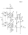
- the transmission according to the invention comprises three parallel shafts 1, 2 and 3.
- the three parallel shafts 1, 2 and 3 are arranged in the longitudinal direction of the agricultural tractor equipped with the transmission and can advantageously be mounted in a triangle.
- the shaft 1 corresponds to the clutch shaft of the powertrain and to the input of the movement. It carries a pinion 4 which is integral therewith.
- the second shaft 2 carries a planetary gear train 5.
- a hydrostatic variator referenced 7 as a whole is arranged in parallel with the main mechanism.
- the hydrostatic variator 7 comprises two hydrostatic elements with variable displacements 8, 9 which, depending on the operating point, can play the role of pump or motor.
- the two hydrostatic elements 8 and 9 are mounted in a closed hydraulic circuit 10.
- the hydrostatic element 8 is mechanically linked to the planetary pinion 11 of the epicyclic gear train 5 via a gear train 12 secured to the shaft 13 of the planetary gear 11.
- the hydrostatic element 9 is mechanically linked to the planetary pinion 14 of the planetary gear train 6 by means of the pinion train 15 secured to the shaft 16 of the planetary pinion 14.
- toothed crown 17 The entry of the movement on each of the planetary gear trains 5 and 6 is done by a toothed crown 17, 18.
- the toothed crown 17 meshes with the pinion 4 secured to the input shaft 1.
- the two toothed crowns 17 and 18 mesh together.
- Each of the toothed rings 17, 18 is linked to the planet carrier 19, 20 of the corresponding planetary gear train 5, 6.
- the toothed rings 17, 18 on the contrary it would be possible for the toothed rings 17, 18 on the contrary to be linked to the rings - exterior 21, 22.
- the output elements of the planetary gear trains 5, 6 are constituted by the rings 21, 22 which mesh with the planet gears 23, 24.
- the rings 21, 22 are therefore secured respectively to the output shafts 2 and 3.
- the transmission movement is output by the shaft 3.
- the power transmitted to the intermediate shaft 2 is transferred to the output shaft 3 by two sets of pinions 25, 26 having two different gear ratios.
- the first set of pinions 25 comprises a pinion 27 mounted freely on the shaft 2 and which can be secured to the latter via of a multi-plate clutch 28.
- the pinion 27 meshes with a pinion 29 of larger diameter secured to the output shaft 3.
- the pinion assembly 26 comprises a pinion 30 mounted freely on the shaft 2 and which can be secured to the latter by means of a multi-plate clutch 31.
- the pinion 30 meshes with a pinion 32 integral with the output shaft 3 and having a diameter less than the pinion 30.
- Either of the two meshing ratios defined by the two sets of pinions 25, 26 between the two shafts 2, 3 can be selected according to the operating point by the multi-plate clutches 28, 31 which can be hydraulically controlled. conventionally by means not shown.
- the embodiment illustrated in FIG. 2 on which the identical parts have the same references differs from the embodiment of FIG. 1 by the following features.
- the input pinion 4 meshes here both with the crowns 17 and 18 of the two planetary gear trains 5 and 6, the input shaft 1 being suitably arranged for this purpose between the shafts 2 and 3.
- the crowns teeth 17 and 18 no longer mesh together.
- the power transmitted by the shafts 2 and 3 is transferred to an additional shaft 3a acting as the output shaft of the movement and which is here arranged coaxially with the input shaft 1.
- a single gear train 33 comprising a pinion 34 secured to the output shaft 3a and a pinion 35 secured to the shaft 3 allows the transfer of power from the shaft 3.
- the transfer of power from the shaft 2 is done by the two sets of pinions 25 , 26 whose pinions 29 and 32 are integral with the output shaft 3a.
- the selection device comprises, as in the previous embodiment, the two multidisk clutches 28 and 31 which make it possible to define two different engagement ratios between the shaft 2 and the output shaft 3a.
- the hydrostatic element 9, whether it plays the role of pump or motor, has zero displacement, the hydrostatic element 8 being at zero speed due to the equal flow rates, to leaks closely, in the hydraulic circuit 10.
- the planetary pinion 11 of the planetary gear train 5 is therefore blocked.
- the speed ratio between the shaft 2 and the input shaft 1 is determined by the characteristics of the gear train 5 and the speed of rotation of the output shaft 3 depends on the choice of the gear ratio by l one or the other of the sets of pinions 25, 26 between the shafts 2 and 3.
- the meshing ratios of the two sets of pinions 25, 26 are equal to 1.95 and 1 / 1.95 respectively.
- the output speeds obtained for these two engagement ratios, in the case where the hydrostatic element 8 is blocked, are the extreme output speeds that it is possible to obtain for the transmission. They are therefore in a ratio of (1.95) 2 or approximately 3.8.
- the two corresponding operating points are called "adaptation points". These two adaptation points A and B are shown on the scale referenced "speed ratio" on the abscissa of the graphs of FIGS. 7 and 8.
- FIGS. 7 and 8 Another particular operating point called “middle adaptation point” and referenced C in FIGS. 7 and 8 is obtained in the case where it is the hydrostatic element 8 which is at zero displacement and the hydrostatic element 9 at zero speed thus blocking the planet wheel 14 of the planetary gear train 6.
- the speed ratio of l output shaft 3 to input shaft 1 is determined, taking into account the blocking of the planet 14 by the characteristics of the planetary gear train 6.
- An output speed is obtained which is located between the output speeds obtained previously for points A and B.
- the speed obtained at point C is actually the geometric mean of the speeds obtained for points A and B.
- the power passing through the hydrostatic variator 7-which includes the hydrostatic elements 8 and 9 is theoretically zero. All of the engine power is found on the output shaft of the gear train 5 or of the gear train 6, the respective planetary pinion 11 or 14 is blocked.
- Figs. 3 and 4 show the circuit of the powers involved for these particular cases.
- FIGS. 5 and 6 there are shown the three parallel shafts 1, 2 and 3 and, in dashed lines schematically, the main elements of the transmission which bear the same references as in the other figures.
- Fig. 3 corresponds to the operation of the adaptation points A and B where the power is transmitted in full by the shaft 2. More specifically illustrated in FIG. 3 the particular case of point B where the power transmission is done by the pinion assembly 25. For point A, the power transmission would be done in the same way by the shaft 2 then by the pinion assembly 26 .
- the transmission according to the invention therefore makes it possible to obtain two operating modes contiguous to the medium adaptation point C.
- the ratio of the extreme speeds which is called the "reason" is for each of the two modes of 1.95, the whole thus having a reason of 3.8.
- the exact speed ratio in the transmission is determined by adjusting the displacement of the hydrostatic elements 8 and 9.
- the gradual increase in the displacement of the hydrostatic element 9 causes the aug progressive mentation of the speed of rotation of the hydrostatic element 8 which in this mode plays the role of hydrostatic motor.
- the speed of rotation of the shaft 2 increases.
- This continuous effect is obtained up to the medium adaptation point C by correspondingly reducing the displacement of the motor 8 which causes a reduction in the speed of rotation of the pump 9 until the planetary pinion 14 of the second planetary gear train 6 is blocked.
- the straight line 36 shows the speed variation of the hydrostatic element 9 while the straight line segments 37 in a finer line show the speed variations of the hydrostatic element 8.
- the parts of the straight lines 36 and 37 in solid line correspond to the operation of the respective hydrostatic elements in hydraulic motor while the dotted parts correspond to the operation in hydraulic pump. It can be seen that the speed of the hydrostatic element 9 (straight line 36) is zero at the middle adaptation point C and maximum for the adaptation points A and B. On the contrary, the speed of rotation of the hydrostatic element 8 ( right 37) is zero at the ends A and B of the two modes and maximum for the middle adaptation point C which corresponds to the change of mode.
- FIGS. 1 and 2 make it possible to obtain, as we have just seen, two contiguous modes. Thanks to the particular arrangement of the various elements of the transmission and in particular the use of three parallel shafts, it is possible to directly couple the hydrostatic elements 8 and 9 at the end of the planetary gear trains 5 and 6. The change of mode is done by changing the meshing ratio between the output shafts 2 and 3 of the two epicyclic gear trains thus allowing two contiguous operating modes to be obtained directly.
- FIG. 9 shows a modification of the transmission illustrated in FIGS. 1 and 2 allowing a third mode to be obtained.
- the output shaft is constituted by two half-shafts 38 and 39 which can be secured and disengaged by a dog clutch 40.
- the half-shaft 38 is secured to the output gear 22 of the train epicyclic gears 6 and pinion 32 of the pinion assembly 26.
- the half-shaft 38 has a toothing of dog clutch 41 which can mesh, when dog clutch device 40 is actuated, with dog clutch teeth 42 fixed to the end of the half-shaft 39 by which the output of the transmission movement takes place.
- the pinion 29 of the second set of pinions 25 is also integral with the half-shaft 39.
- the half-shafts 38 and 39 are made integral by the device 40 and the operation is identical to that previously described.
- the two half-shafts 38 and 39 are separated by means of the dog clutch 40 and the two sets of pinions 25 and 26 are simultaneously engaged by clutches 28 and 31.
- the power supplied to the output of the planetary gear train 6 on the half-shaft 38 is thus first retransmitted on the shaft 1 as can be seen in the diagram of the fig. 6.
- An additional speed range is thus obtained, the control of which is effected by manual engagement of the dog clutch device 40.
- the complete automation of a transmission such as that illustrated in FIGS. 1, 2 and 9 can be obtained using a microprocessor ensuring for example a minimum consumption as a function of a choice made by the user relating to the character. Constant of the forward speed or the speed of the vehicle engine.
- a hydraulic system can then automatically carry out the control of the jacks for adjusting the displacements of the two hydraulic elements 8 and 9 as well as the control of the multi-plate clutches 28 and 31 allowing the effective adjustment of the speed ratio.
- FIG. 10 there is illustrated a device allowing the selection and the automatic change of the gear ratio between the two output shafts 2 and 3 of the planetary gear trains 5 and 6.
- This device comprises , as illustrated, a double dog clutch 43 mounted on the output shaft 2 of the planetary gear train 5 ensuring the mechanical locking of one or other of the engagement ratios defined by the pinion assemblies 25 and 26.
- the input pinion 4 meshes directly with the toothed crown 17 which is integral with the crown 21 of the epicyclic gear train 5, the output being here by the planet carrier 19.
- the output of power of the planetary gear train 6 is made by the planet carrier 20 while the crown 22 is integral with the toothed crown 18 which meshes with the toothed crown 17.
- the device further comprises an auxiliary pump 44, driven by the engine of the vehicle not shown in the figure, said pump 44 being mounted in an auxiliary hydraulic circuit comprising a supply branch 45 and a return branch 46.
- the auxiliary circuit is mounted as a bypass on the hydraulic element 8.
- a two-way, four-way shut-off solenoid valve 47 is mounted in the hydraulic circuit 10 between the two hydrostatic elements 8 and 9 so as to be able to isolate the hydrostatic element 9 when the valve 47 is placed in the opposite position to that which is shown in fig. 10.
- a distributor 48 for example with electric control, with four channels and three positions, is mounted in the auxiliary circuit comprising the pipes 45 and 46 in order to allow the reversal of the direction of supply by the pump 44. In this way it is possible to obtain the desired synchronization both to switch from the first mode to the second and to switch from the second mode to the first.
- a relief valve 49 completes the auxiliary circuit and allows the circuit to be discharged through line 45 in the tank 50.
- the auxiliary pump 44 is preferably a positive displacement pump, generally with gears, which delivers at zero pressure when it is not used. In one or other of the transmission's operating modes, the double dog clutch 43 is locked on the gear ratio corresponding to one of the two sets of pinions 25 or 26.
- the final displacement of the element 8 is such that the ratio of the displacement of the element 8 to the displacement of the auxiliary pump 44 is the inverse of the value of the relative speed which is wishes to obtain for element 8 (in the example considered 2.1 or 1.05).
- the speed synchronism necessary to select the new mode selected is obtained using the double clutch 43.
- the valve 49 ensures the discharge of the auxiliary circuit until stabilization has taken place. We can then engage the gear ratio of the other set of gears corresponding to the chosen mode and start the continuous variation of the speed ratio inside said mode.
- the double dog 43 can be replaced by simple dog devices arranged on each of the shafts 2 or 3. It is also possible to replace the double dog 43 by a double synchronization system, that is to say a dog device provided with cones friction and a device for preventing the dog from passing in the absence of synchronization of the parts to be dogged. In this case, the support force of the actuating cylinder of the synchronization device only results in the interlocking by clutching of the members corresponding to the desired engagement ratio only when the exact synchronism of these members has been obtained by the variation of the displacement of the hydrostatic element 8.
- the transmission according to the invention can be used on an agricultural or forestry tractor and in general in any type of work which, because of the poor soil resistance, requires a flexibility of use almost comparable to that of a public works machine.
- a continuous variation of the tractor speed is obtained from 3 to 11 km / h and in the road range, a variation continuous speed from 8 to 30 km / h for nominal engine speed.
Landscapes
- Engineering & Computer Science (AREA)
- General Engineering & Computer Science (AREA)
- Mechanical Engineering (AREA)
- Structure Of Transmissions (AREA)
Applications Claiming Priority (2)
| Application Number | Priority Date | Filing Date | Title |
|---|---|---|---|
| FR8213377 | 1982-07-30 | ||
| FR8213377A FR2531173B1 (fr) | 1982-07-30 | 1982-07-30 | Transmission a derivation de puissance hydraulique |
Publications (2)
| Publication Number | Publication Date |
|---|---|
| EP0101358A1 true EP0101358A1 (de) | 1984-02-22 |
| EP0101358B1 EP0101358B1 (de) | 1987-12-09 |
Family
ID=9276505
Family Applications (1)
| Application Number | Title | Priority Date | Filing Date |
|---|---|---|---|
| EP19830401544 Expired EP0101358B1 (de) | 1982-07-30 | 1983-07-27 | Hydrostatisches leistungsverzweigtes Getriebe |
Country Status (4)
| Country | Link |
|---|---|
| EP (1) | EP0101358B1 (de) |
| DE (1) | DE3374895D1 (de) |
| ES (1) | ES524595A0 (de) |
| FR (1) | FR2531173B1 (de) |
Cited By (7)
| Publication number | Priority date | Publication date | Assignee | Title |
|---|---|---|---|---|
| EP0153612B1 (de) * | 1984-03-01 | 1988-04-20 | Schweizerische Lokomotiv- und Maschinenfabrik | Antriebseinrichtung mit variabler Gesamtübersetzung und Langsam-Dreheinrichtung |
| FR2634850A1 (fr) * | 1988-07-27 | 1990-02-02 | Man Nutzfahrzeuge Ag | Ensemble d'entrainement, notamment pour un vehicule a roues, tout terrain |
| GB2268237A (en) * | 1992-06-27 | 1994-01-05 | Massey Ferguson Sa | Continuously variable transmission has two epicyclic trains and hydrostatic shunt loop |
| EP1522491A3 (de) * | 2003-09-22 | 2005-06-22 | Kanzaki Kokyukoki Mfg. Co., Ltd. | Schiffsantriebssystem |
| EP1342937A3 (de) * | 2002-03-06 | 2008-03-19 | CNH Belgium N.V. | Stufenlos regelbares Getriebe |
| WO2008015549A3 (en) * | 2006-08-03 | 2008-04-17 | Toyota Motor Co Ltd | Power split dual input shaft transmission for vehicle |
| WO2016046730A1 (en) * | 2014-09-22 | 2016-03-31 | Rostamlou Alireza | Geared continuously variable transmission |
Citations (2)
| Publication number | Priority date | Publication date | Assignee | Title |
|---|---|---|---|---|
| GB2014671A (en) * | 1978-02-16 | 1979-08-30 | Dana Corp | Hydromechanical Transmission |
| GB2016098A (en) * | 1978-03-08 | 1979-09-19 | Maschf Augsburg Nuernberg Ag | Power division transmission |
-
1982
- 1982-07-30 FR FR8213377A patent/FR2531173B1/fr not_active Expired
-
1983
- 1983-07-27 DE DE8383401544T patent/DE3374895D1/de not_active Expired
- 1983-07-27 EP EP19830401544 patent/EP0101358B1/de not_active Expired
- 1983-07-29 ES ES524595A patent/ES524595A0/es active Granted
Patent Citations (2)
| Publication number | Priority date | Publication date | Assignee | Title |
|---|---|---|---|---|
| GB2014671A (en) * | 1978-02-16 | 1979-08-30 | Dana Corp | Hydromechanical Transmission |
| GB2016098A (en) * | 1978-03-08 | 1979-09-19 | Maschf Augsburg Nuernberg Ag | Power division transmission |
Cited By (14)
| Publication number | Priority date | Publication date | Assignee | Title |
|---|---|---|---|---|
| EP0153612B1 (de) * | 1984-03-01 | 1988-04-20 | Schweizerische Lokomotiv- und Maschinenfabrik | Antriebseinrichtung mit variabler Gesamtübersetzung und Langsam-Dreheinrichtung |
| FR2634850A1 (fr) * | 1988-07-27 | 1990-02-02 | Man Nutzfahrzeuge Ag | Ensemble d'entrainement, notamment pour un vehicule a roues, tout terrain |
| GB2268237A (en) * | 1992-06-27 | 1994-01-05 | Massey Ferguson Sa | Continuously variable transmission has two epicyclic trains and hydrostatic shunt loop |
| GB2268237B (en) * | 1992-06-27 | 1995-04-05 | Massey Ferguson Sa | Transmissions |
| US5421790A (en) * | 1992-06-27 | 1995-06-06 | Massey-Ferguson S.A. | Continuously variable transmission |
| EP1342937A3 (de) * | 2002-03-06 | 2008-03-19 | CNH Belgium N.V. | Stufenlos regelbares Getriebe |
| US6988917B2 (en) | 2003-09-22 | 2006-01-24 | Kazuhiko Ohtsuki | Boat propulsion system |
| US7168997B2 (en) | 2003-09-22 | 2007-01-30 | Kazuhiko Ohtsuki | Boat propulsion system |
| EP1762486A1 (de) * | 2003-09-22 | 2007-03-14 | Kanzaki Kokyukoki Mfg. Co., Ltd. | Schiffsantriebssystem |
| EP1522491A3 (de) * | 2003-09-22 | 2005-06-22 | Kanzaki Kokyukoki Mfg. Co., Ltd. | Schiffsantriebssystem |
| WO2008015549A3 (en) * | 2006-08-03 | 2008-04-17 | Toyota Motor Co Ltd | Power split dual input shaft transmission for vehicle |
| US8251848B2 (en) | 2006-08-03 | 2012-08-28 | Toyota Jidosha Kabushiki Kaisha | Power split dual input shaft transmission for vehicle |
| DE112007000539B4 (de) * | 2006-08-03 | 2016-08-04 | Toyota Jidosha Kabushiki Kaisha | Getriebe für ein Fahrzeug |
| WO2016046730A1 (en) * | 2014-09-22 | 2016-03-31 | Rostamlou Alireza | Geared continuously variable transmission |
Also Published As
| Publication number | Publication date |
|---|---|
| FR2531173A1 (fr) | 1984-02-03 |
| FR2531173B1 (fr) | 1988-09-23 |
| EP0101358B1 (de) | 1987-12-09 |
| ES8404487A1 (es) | 1984-05-01 |
| ES524595A0 (es) | 1984-05-01 |
| DE3374895D1 (en) | 1988-01-21 |
Similar Documents
| Publication | Publication Date | Title |
|---|---|---|
| FR2805587A1 (fr) | Dispositif de transmission automatise a engrenages, en particulier pour vehicule automobile | |
| FR2521078A1 (fr) | Mecanisme de changement de vitesse pour vehicule motorise | |
| FR2971572A1 (fr) | Boite de vitesses a double embrayage comportant une liaison de transfert | |
| FR2634850A1 (fr) | Ensemble d'entrainement, notamment pour un vehicule a roues, tout terrain | |
| FR2723777A1 (fr) | Train de transmission de puissance d'une transmission automatique pour vehicule | |
| FR2598195A1 (fr) | Boite de vitesses automatique a trains planetaires. | |
| EP0101358B1 (de) | Hydrostatisches leistungsverzweigtes Getriebe | |
| WO2005119101A1 (fr) | Transmission infiniment variable a derivation de puissance a deux modes de fonctionnement commandee par un baladeur a crabot, pour vehicule automobile | |
| FR2862363A1 (fr) | Dispositif de transmission a rapports multiples, notamment pour l'automobile | |
| EP4192725B1 (de) | Getriebevorrichtung für ein durch menschenkraft angetriebenes fahrzeug | |
| EP0014122B1 (de) | Hydromechanische Rutsch-Lenkungsvorrichtung | |
| FR2531515A1 (en) | Gearbox with integrated range doubler. | |
| FR2524954A1 (fr) | Dispositif de transmission automatique a variation continue | |
| FR2702814A1 (fr) | Transmission automatique à vitesse variable. | |
| EP1627163A1 (de) | Doppelkupplungsgetriebe mit zwei vorgelegewellen | |
| EP1801455A1 (de) | Manuelles oder automatisiertes Lastschaltgetriebe mit drei parallelen Wellen | |
| FR2801010A1 (fr) | Dispositif de transmission et de conversion de couple utilisant une boite de vitesses et deux embrayages | |
| FR2608246A1 (fr) | Dispositif de transmission | |
| EP0017993B1 (de) | Epizykloidalzahnradschaltgetriebe und Drehmomentwandler mit vier Vorwärtsgängen und Drehmomentwandlerüberbrückung | |
| FR2597184A1 (fr) | Convertisseur de couple a etage-multiple et trois-elements | |
| FR2679975A1 (fr) | Transmission hydromecanique pour vehicules automobiles. | |
| FR2853705A1 (fr) | Boite de vitesses pour vehicule automobile | |
| FR2651292A1 (fr) | Transmission combinant une transmission a boite de vitesses et une transmission hydraulique pour vehicule. | |
| FR2861447A1 (fr) | Boite de vitesse pour vehicule automobile. | |
| EP1249361B1 (de) | Getriebe für Kraftfahrzeug mit zusätzlicher, am Differential angeordneter und von Hand geschalteter Untersetzung |
Legal Events
| Date | Code | Title | Description |
|---|---|---|---|
| PUAI | Public reference made under article 153(3) epc to a published international application that has entered the european phase |
Free format text: ORIGINAL CODE: 0009012 |
|
| 17P | Request for examination filed |
Effective date: 19830730 |
|
| AK | Designated contracting states |
Designated state(s): BE DE GB IT NL |
|
| GRAA | (expected) grant |
Free format text: ORIGINAL CODE: 0009210 |
|
| AK | Designated contracting states |
Kind code of ref document: B1 Designated state(s): BE DE GB IT NL |
|
| ITF | It: translation for a ep patent filed | ||
| GBT | Gb: translation of ep patent filed (gb section 77(6)(a)/1977) | ||
| REF | Corresponds to: |
Ref document number: 3374895 Country of ref document: DE Date of ref document: 19880121 |
|
| PLBE | No opposition filed within time limit |
Free format text: ORIGINAL CODE: 0009261 |
|
| STAA | Information on the status of an ep patent application or granted ep patent |
Free format text: STATUS: NO OPPOSITION FILED WITHIN TIME LIMIT |
|
| 26N | No opposition filed | ||
| PG25 | Lapsed in a contracting state [announced via postgrant information from national office to epo] |
Ref country code: BE Effective date: 19890731 |
|
| BERE | Be: lapsed |
Owner name: REGIE NATIONALE DES USINES RENAULT Effective date: 19890731 |
|
| PG25 | Lapsed in a contracting state [announced via postgrant information from national office to epo] |
Ref country code: NL Effective date: 19900201 |
|
| NLV4 | Nl: lapsed or anulled due to non-payment of the annual fee | ||
| PGFP | Annual fee paid to national office [announced via postgrant information from national office to epo] |
Ref country code: GB Payment date: 19900618 Year of fee payment: 8 |
|
| PGFP | Annual fee paid to national office [announced via postgrant information from national office to epo] |
Ref country code: DE Payment date: 19900622 Year of fee payment: 8 |
|
| ITTA | It: last paid annual fee | ||
| PG25 | Lapsed in a contracting state [announced via postgrant information from national office to epo] |
Ref country code: GB Effective date: 19910727 |
|
| GBPC | Gb: european patent ceased through non-payment of renewal fee | ||
| PG25 | Lapsed in a contracting state [announced via postgrant information from national office to epo] |
Ref country code: DE Effective date: 19920401 |