EP0101361A1 - Vorrichtung für die Umlenkung einer zeitweise auftretenden Kraft und zum Halten eines faltbaren Auslegers in der Ruhestellung für ein Raumfahrzeug - Google Patents
Vorrichtung für die Umlenkung einer zeitweise auftretenden Kraft und zum Halten eines faltbaren Auslegers in der Ruhestellung für ein Raumfahrzeug Download PDFInfo
- Publication number
- EP0101361A1 EP0101361A1 EP83401565A EP83401565A EP0101361A1 EP 0101361 A1 EP0101361 A1 EP 0101361A1 EP 83401565 A EP83401565 A EP 83401565A EP 83401565 A EP83401565 A EP 83401565A EP 0101361 A1 EP0101361 A1 EP 0101361A1
- Authority
- EP
- European Patent Office
- Prior art keywords
- stops
- axis
- diversion device
- appendix
- force diversion
- Prior art date
- Legal status (The legal status is an assumption and is not a legal conclusion. Google has not performed a legal analysis and makes no representation as to the accuracy of the status listed.)
- Granted
Links
Images

Classifications
-
- B—PERFORMING OPERATIONS; TRANSPORTING
- B64—AIRCRAFT; AVIATION; COSMONAUTICS
- B64G—COSMONAUTICS; VEHICLES OR EQUIPMENT THEREFOR
- B64G1/00—Cosmonautic vehicles
- B64G1/22—Parts of, or equipment specially adapted for fitting in or to, cosmonautic vehicles
- B64G1/222—Parts of, or equipment specially adapted for fitting in or to, cosmonautic vehicles for deploying structures between a stowed and deployed state
- B64G1/2228—Parts of, or equipment specially adapted for fitting in or to, cosmonautic vehicles for deploying structures between a stowed and deployed state characterised by the hold-down or release mechanisms
-
- B—PERFORMING OPERATIONS; TRANSPORTING
- B64—AIRCRAFT; AVIATION; COSMONAUTICS
- B64G—COSMONAUTICS; VEHICLES OR EQUIPMENT THEREFOR
- B64G1/00—Cosmonautic vehicles
- B64G1/22—Parts of, or equipment specially adapted for fitting in or to, cosmonautic vehicles
- B64G1/42—Arrangements or adaptations of power supply systems
- B64G1/44—Arrangements or adaptations of power supply systems using radiation, e.g. deployable solar arrays
- B64G1/443—Photovoltaic cell arrays
-
- B—PERFORMING OPERATIONS; TRANSPORTING
- B64—AIRCRAFT; AVIATION; COSMONAUTICS
- B64G—COSMONAUTICS; VEHICLES OR EQUIPMENT THEREFOR
- B64G1/00—Cosmonautic vehicles
- B64G1/22—Parts of, or equipment specially adapted for fitting in or to, cosmonautic vehicles
- B64G1/66—Arrangements or adaptations of apparatus or instruments, not otherwise provided for
Definitions
- the invention relates to devices for holding, in the storage position on a structure, an extendable appendage around a hinge axis. It is particularly applicable to deployable appendages mounted on spacecraft. Such vehicles use appendages (solar generators, reflectors, masts, telecommunications elements, etc.) which should be stored on the body of the vehicles during the launch phase.
- appendages solar generators, reflectors, masts, telecommunications elements, etc.
- these objects are held on the body of the vehicle by several temporary fixing points, to which are added the point or points of connection of the appendix to the vehicle which remain after the deployment of these appendages.
- These permanent connection points generally include mechanisms for orienting or positioning the appendages to enable them to fulfill their mission in orbit.
- the purpose of the rigidity requirement is to ensure frequency decoupling between the launcher, the satellite and the appendages, this in order to limit the loads and therefore allow the production of elements of minimum mass.
- the permanent link point of the appendix on the satellite is a holding point capable of supporting the loads induced by the launch.
- Container holding devices for deployable and orientable solar panels are also known; for example, a solution described in patent FR No. 2,470,727 (79 / 29,681) of the applicant consists in locking each articulation with a deployable arm, which multiplies the number of orders to be given to release the deployment device and does not provide optimal rigidity.
- the invention aims to overcome these drawbacks and aims in particular to preserve as much as possible the control mechanisms (orientation and / or positioning) by deriving all or part of the temporary forces undergone by the appendages during the launch phases, directly in the structure of the vehicle, without passing them through the control mechanism as in the prior art.
- the invention thus provides a device for deriving temporary force for maintaining in the storage position on a structure of a space vehicle an appendage deployable around an axis of articulation under the action of '' a control mechanism, intended to mechanically relieve the latter, characterized in that it comprises holding means, external to the control mechanism, adapted to apply to the appendage, in said storage position, longitudinal bending preloads , reducing at the level of the articulation axis to a pure prestressing torque tending to cause the deployment of the appendix.
- the invention more particularly provides a temporary force diversion device of the aforementioned kind, characterized in that the means for holding the appendage comprise a first group of stops, integral with the structure, a second group of stops, integral with the appendix, and at least one temporary locking means connecting the appendix and the structure at a distance from the hinge pin, these stops being arranged so that in the appendage storage position, during locking of said means, each of the stops of the first group, divided into two sub-groups arranged along the articulation axis on either side of the control mechanism, is pressed against one of the stops of the second group, distributed in the same way in two sub-groups arranged along the hinge axis on either side of the control mechanism.
- such a device comprises two stops in each sub-group, diametrically opposite with respect to the axis of articulation.
- the confrontation surfaces between stops are for example planar and coplanar, transmitting the tangential forces from the appendage towards the structure, either by dry friction, either by shearing or partial embedding of these, the centering of the stops relative to the articulation axis can be provided by flanges, or elements of revolution integral with the stops, symmetrical with respect to the said articulation axis.
- the holding means are external to the control mechanism and that they only cause pure torque in the supports of the fixed stops, they lead to a great reduction, if not a elimination, of the forces undergone by the latter during the launch phase.
- the great simplicity of the device since it is essentially static, gives it high reliability; there is no unlocking control to be provided at the level of the stops, therefore of the articulation axis, since the facing stops separate when the appendix is deployed and leave the appendix an angular movement of all the more important as the number of stops is low. Unlocking can now be obtained in response to a single order given to the aforementioned additional locking means, for example by a pyrotechnic phenomenon.
- the stops are all located in one plane, the deployment of the appendix authorizes the operation of the orientation control mechanism.
- the invention makes it possible to better "standardize” the control mechanisms, the choice of the latter no longer requiring the prior study of the temporary loads that these would have to undergo during launching.
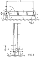
- a deployable appendage 1 is articulated around a hinge pin 10 under the action of a control mechanism 2 covered by a yoke.
- the hinge axis 10 is, in the appendage storage position, parallel to the axis Z.
- This hinge axis is, moreover , but this is not necessarily the case for all the appendices to which the invention may apply, mounted rotating around an axis of rotation 11, substantially parallel to the pivot axis of orientation Y, under the control of the control mechanism 2.
- Stops 4 (represented by arrows), forming a first group, are integral with a structure 5, parallel to which the appendix 1 is folded into the storage position, by means of uprights 8. These stops 4 are distributed in two sub-groups arranged along the hinge axis 10 on either side of the control mechanism 2.
- Movable stops 3 forming a second group, are integral with the appendix 1 and are arranged on both sides 'other of the latter, and of the control mechanism, along the axis of articulation 10.
- the stops of each sub-group are two in number, are more planar, and, moreover, radial, coplanar and diametrically opposite. We will see later that this is not necessarily always the case, despite the advantages of such a configuration.
- the fixed stops 4 and mobile 3 are applied against each other.
- the positioning of these stops is adapted to cause, during the implementation of the additional temporary locking means 9 ensuring the temporary fixing of the appendix 1 on a base 6 secured to the structure 5 of the vehicle, the appearance of preloads of longitudinal flexion, in the XY plane, which are reduced, at the level of the articulation axis 10, to a pure torque of prestressing tending to cause the deployment of the appendix.
- most of the stresses existing in appendix 1 in the vicinity of the articulation axis are tension-compression stresses which are balanced by the reactions of the fixed stops 4.
- the shear stress is transmitted to the fixed stops 4 by contact with the movable stops 3. It therefore does not induce, for the axis, any radial force.
- the articulation axis therefore does not run the risk of being distorted or of distorting the control mechanism 2 to which it is linked.
- the locking means 9 is not detailed, its nature not being the subject of the present request.
- These are for example conventional pyrotechnic means arranged parallel to the axis Z between the appendix 1 and the base em 6, the latter then having sides rising on either side of the appendage to serve as support for said means.
- the firing of such pyrotechnic means or the unlocking of the member 9 automatically ensures the separation of the fixed and mobile stops which therefore do not require specific unlocking elements.
- Figure 2 shows Appendix 1 in the unfolded position. It has undergone, relative to its position in Figure 2, a 90 ° rotation and is parallel to the Y axis of the reference trihedron. Although advantageous since it brings the free end 1a of the appendix to a maximum distance from the structure 5, it is obvious that this configuration does not correspond to the only average service position that an appendage can adopt in the frame. of the invention.
- the pressure of confrontation (face to face joining) between stops must correspond to the maximum forces which are likely to appear, under penalty of decreasing the quality of the derivations of forces parallel to the plane YZ, which are carried out in the plane of confrontation of stops. If P is the force applied to the appendix at the complementary temporary locking member 9, if L is the distance between the base 6 and the hinge pin 10, and if d is the average distance between stops of the same sub-group, the confrontation pressure between stops is linked to .
- the derivation of the forces F YZ parallel to the plane YZ can be ensured in several ways, most often by dry friction or by reciprocal embedding of the thrust faces, as is indicated below with regard to the exemplary embodiments illustrated by FIGS. 3 to 10.
- the fixed stops 4 are carried by two uprights 8 arranged on either side of the control mechanism 2, but it is recalled that this number is arbitrary.
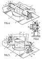
- FIG. 3 corresponds to a derivation of the temporary forces F YZ parallel to the plane YZ by dry friction. If Cf is the coefficient of friction between stops, these forces are correctly derived towards the structure provided that they check the inequality:
- the stops are represented as simple protrusions of the uprights 8 and of the appendix 1 parallel to the articulation axis 10. It should be noted that the movable stops 3 on the same side of the appendix are not differentiated, being formed of a portion of plate, perpendicular to the longitudinal axis of the appendage, and extending the axis of articulation 10.
- Figures 4 and 5 illustrate a hand structure your appendix quite similar to the previous one. Many variations of form have been made. It should be noted in particular that the fixed stops 4 are here formed by the flat head of attached members, such as screws 7, passing through protuberances 4a parallel to the axis Z , similar to those which constitute the fixed stops of the figure 3.
- FIG. 6 illustrates, by way of example, some optional peripheral means, adapted to ensure that the stops are wedged together, without inadvertent sliding of one with respect to the other.
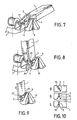
- Figures 7 and 8 illustrate an embodiment of bypass according to the invention which differs essentially from that of Figures 4 and 5 in that the adjustment of the surfaces of confrontation of associated stops is ensured by means of screws 17 reported not to the fixed uprights 8, but to appendix 1.
- the facing surfaces are the flat heads 3a of the screws 17 and the stops 4.
- FIG. 9 illustrates an embodiment according to the invention where the derivation of the forces parallel to the plane YZ is ensured, no longer solely by phenomena of dry friction, but also thanks to the shear strength of pins 27 carried by one stops, movable in the proposed example, adapted to be temporarily embedded in cavities or channels 37 of complementary shape; a position adjustment of the pin 27, or of the cavity 37 in a plan parallel to YZ is of course advantageous for making the most of these built-in elements.
- FIG. 10 shows diagrammatically some possible variants of the arrangement of the mobile stops 3 linked to the appendix 1.
- FIG. 10a there are two stops; their confrontation surfaces with fixed stops 4 are coplanar with the hinge axis 10 along a plane whose inclination relative to the plane YZ is advantageously chosen so that the maximum temporary forces to be derived are perpendicular to said surfaces of confrontation.
- Figure 10b shows an arrangement with at least 3 radial stops per subgroup; the derivation of the forces is also obtained by dry friction, the confrontation surfaces not being coplanar; this bypass is further facilitated due to the increased number of stops.
- FIG. 10c proposes an arrangement with two non-radial but parallel stops.
- stops does not facilitate obtaining a rotation of the appendage around its axis after deployment without limitation by contact with fixed and mobile stops.
- confrontation surfaces could thus not be flat, for example having complementary reliefs (such as pyramids etc.) distributed periodically or not. They can be tilted in relation to each of the three axes. They can have curved shapes such as portions of surfaces of revolution (spheres, cones) whose axes are parallel to the bearing reactions on the stops.
- the number of fixing bases is arbitrary.
Landscapes
- Engineering & Computer Science (AREA)
- Remote Sensing (AREA)
- Aviation & Aerospace Engineering (AREA)
- Pivots And Pivotal Connections (AREA)
- Details Of Aerials (AREA)
- Tents Or Canopies (AREA)
- Orthopedics, Nursing, And Contraception (AREA)
- Prostheses (AREA)
Applications Claiming Priority (2)
| Application Number | Priority Date | Filing Date | Title |
|---|---|---|---|
| FR8213361A FR2531032A1 (fr) | 1982-07-30 | 1982-07-30 | Dispositif de derivation d'effort temporaire pour maintien en position de stockage d'un appendice deployable pour vehicule spatial |
| FR8213361 | 1982-07-30 |
Publications (2)
| Publication Number | Publication Date |
|---|---|
| EP0101361A1 true EP0101361A1 (de) | 1984-02-22 |
| EP0101361B1 EP0101361B1 (de) | 1985-12-11 |
Family
ID=9276499
Family Applications (1)
| Application Number | Title | Priority Date | Filing Date |
|---|---|---|---|
| EP83401565A Expired EP0101361B1 (de) | 1982-07-30 | 1983-07-28 | Vorrichtung für die Umlenkung einer zeitweise auftretenden Kraft und zum Halten eines faltbaren Auslegers in der Ruhestellung für ein Raumfahrzeug |
Country Status (6)
| Country | Link |
|---|---|
| US (1) | US4529154A (de) |
| EP (1) | EP0101361B1 (de) |
| JP (1) | JPS5941000A (de) |
| CA (1) | CA1259594A (de) |
| DE (1) | DE3361493D1 (de) |
| FR (1) | FR2531032A1 (de) |
Cited By (4)
| Publication number | Priority date | Publication date | Assignee | Title |
|---|---|---|---|---|
| DE3615264A1 (de) * | 1986-05-06 | 1987-11-12 | Messerschmitt Boelkow Blohm | Vorrichtung fuer die teilentfaltung von solargeneratoren |
| EP0751066A1 (de) * | 1995-06-27 | 1997-01-02 | DORNIER GmbH | Gelenk für einen Auslegerarm an einem Satelliten |
| EP0776826A3 (de) * | 1994-09-28 | 1997-08-27 | Loral Space Systems Inc | Entfaltungsgelenksvorrichtung |
| US6010096A (en) * | 1998-07-22 | 2000-01-04 | Space Systems/Loral, Inc. | Deployment restraint and sequencing device |
Families Citing this family (4)
| Publication number | Priority date | Publication date | Assignee | Title |
|---|---|---|---|---|
| US5864320A (en) * | 1996-08-06 | 1999-01-26 | Space Systems/Loral, Inc. | Synchronous rotation dual-axis mechanical hinge assemblies |
| DE10061773B4 (de) * | 2000-12-12 | 2005-08-18 | Eads Astrium Gmbh | Separationsrahmen zur Trennung mehrerer axial angeordneter Satelliten |
| US7010834B2 (en) * | 2002-09-10 | 2006-03-14 | Nokia Corporation | Hinge assembly, and associated method, providing multiple axes of rotation |
| JP4093038B2 (ja) * | 2002-12-06 | 2008-05-28 | 日本電気株式会社 | 折り畳み式携帯装置およびそのヒンジ機構 |
Family Cites Families (11)
| Publication number | Priority date | Publication date | Assignee | Title |
|---|---|---|---|---|
| US167576A (en) * | 1875-09-07 | Improvement in hinges | ||
| US1246246A (en) * | 1916-09-27 | 1917-11-13 | Augustus W Dickerson | Automobile-hood. |
| US1612656A (en) * | 1923-11-30 | 1926-12-28 | Salin Rachel | Hinge attachment |
| GB269005A (en) * | 1926-06-14 | 1927-04-14 | Heeley And Peart Ltd | Improvements relating to hinges |
| US2498558A (en) * | 1945-04-21 | 1950-02-21 | Lantz Alpha Perry | Pivotal mounting and brace for ironing boards |
| GB844290A (en) * | 1957-03-11 | 1960-08-10 | Felix Brannock Power | Improvements in and relating to hinges |
| US3175081A (en) * | 1963-04-02 | 1965-03-23 | Mcphilben Mfg Co Inc | Luminaire |
| US4133501A (en) * | 1975-09-30 | 1979-01-09 | Communications Satellite Corporation | Self-deployable solar cell panel |
| FR2452693A1 (fr) * | 1979-03-30 | 1980-10-24 | Aerospatiale | Dispositif de verrouillage temporaire pour volant d'inertie |
| FR2470727A1 (fr) * | 1979-12-03 | 1981-06-12 | Aerospatiale | Dispositif de deploiement des elements d'un bras d'eloignement d'un equipement pour engin spatial |
| DE3215432C2 (de) * | 1982-04-24 | 1986-10-30 | Messerschmitt-Bölkow-Blohm GmbH, 8000 München | Niederhaltevorrichtung für entfaltbare Solargeneratoren |
-
1982
- 1982-07-30 FR FR8213361A patent/FR2531032A1/fr active Granted
-
1983
- 1983-07-28 US US06/518,269 patent/US4529154A/en not_active Expired - Fee Related
- 1983-07-28 CA CA000433431A patent/CA1259594A/en not_active Expired
- 1983-07-28 EP EP83401565A patent/EP0101361B1/de not_active Expired
- 1983-07-28 DE DE8383401565T patent/DE3361493D1/de not_active Expired
- 1983-07-29 JP JP58140455A patent/JPS5941000A/ja active Granted
Cited By (6)
| Publication number | Priority date | Publication date | Assignee | Title |
|---|---|---|---|---|
| DE3615264A1 (de) * | 1986-05-06 | 1987-11-12 | Messerschmitt Boelkow Blohm | Vorrichtung fuer die teilentfaltung von solargeneratoren |
| FR2598382A1 (fr) * | 1986-05-06 | 1987-11-13 | Messerschmitt Boelkow Blohm | Dispositif pour le deploiement partiel de generateurs solaires |
| EP0776826A3 (de) * | 1994-09-28 | 1997-08-27 | Loral Space Systems Inc | Entfaltungsgelenksvorrichtung |
| EP0751066A1 (de) * | 1995-06-27 | 1997-01-02 | DORNIER GmbH | Gelenk für einen Auslegerarm an einem Satelliten |
| US5779194A (en) * | 1995-06-27 | 1998-07-14 | Dornier Gmbh | Joint for a cantilever arm on a satellite |
| US6010096A (en) * | 1998-07-22 | 2000-01-04 | Space Systems/Loral, Inc. | Deployment restraint and sequencing device |
Also Published As
| Publication number | Publication date |
|---|---|
| FR2531032A1 (fr) | 1984-02-03 |
| EP0101361B1 (de) | 1985-12-11 |
| JPS5941000A (ja) | 1984-03-06 |
| US4529154A (en) | 1985-07-16 |
| CA1259594A (en) | 1989-09-19 |
| DE3361493D1 (en) | 1986-01-23 |
| JPH0474240B2 (de) | 1992-11-25 |
| FR2531032B1 (de) | 1985-03-01 |
Similar Documents
| Publication | Publication Date | Title |
|---|---|---|
| EP1676776B1 (de) | Verbindungsvorrichtung für Elemente einer Raumfahrtausrüstung mit flexiblen ausbringbaren Blättern | |
| EP2468629B1 (de) | Entfaltbare starre Großstrukturen | |
| EP1415909B1 (de) | Gelenkige Sonnenzellenpanelanordnung und Raumfahrzeug | |
| EP0441669B1 (de) | Niederhaltersystem für entklappbare Elemente an einem Raumflugkörper | |
| FR2781454A1 (fr) | Dispositif de retenue et de mise en sequence de deploiement | |
| EP3003860B1 (de) | Raumfahrzeug mit mindestens einem paar von tragarmen mit einem hohlen montagemodul und verfahren zur anwendung solch eines fahrzeugs | |
| FR2742220A1 (fr) | Appareil pour deplier et fixer les ailettes d'un engin | |
| FR2651843A1 (fr) | Systeme de verrouillage a came. | |
| EP0101361B1 (de) | Vorrichtung für die Umlenkung einer zeitweise auftretenden Kraft und zum Halten eines faltbaren Auslegers in der Ruhestellung für ein Raumfahrzeug | |
| WO1996002418A1 (fr) | Systeme pour deployer/replier deux elements, avec verrouillage par came desdits elements deployes | |
| FR2776984A1 (fr) | Dispositif de commande d'une rotation relative entre deux elements articules et structure mecanique deployable, notamment pour vehicule spatial, utilisant au moins un dispositif de ce type | |
| FR2778028A1 (fr) | Reflecteur et element de reflecteur pour des antennes d'application spatiales ainsi que procede pour deployer un reflecteur | |
| FR2818239A1 (fr) | Structure d'assemblage sur un vehicule spatial | |
| EP0444996B1 (de) | Vorrichtung für die Befestigung einer Lenksäule an den Aufbau eines Kraftfahrzeuges | |
| FR2707250A1 (fr) | Mécanisme de verrouillage à angle variable pour spationef. | |
| EP0003478B1 (de) | Sonnenenergiekollektor | |
| EP1692428B1 (de) | Befestigungsvorrichtung für feuerdetektionssystem | |
| EP0738656A1 (de) | Einziehsteuervorrichtung einer bewegbaren Struktur | |
| EP0330550B1 (de) | Niederhalter-System für entklappbare Elemente an Raumflugkörpern | |
| EP0126671A1 (de) | Vorrichtung zur flexiblen Befestigung einer Nutzlast auf einer Auflagefläche, namentlich eines Präzisionsinstrumentes auf einem Raumfahrzeug | |
| EP0458677B1 (de) | Drehmomentbegrenzungseinrichtung und entfaltbares Verlängerungsstück eines, mit einer solchen Einrichtung ausgerüsteten, Raumflugkörpers | |
| CA2931924A1 (fr) | Structure segmentee, en particulier pour reflecteur d'antenne de satellite, pourvue d'au moins un dispositif de deploiement a rotation et translation | |
| FR2641344A1 (fr) | Dispositif de fixation d'un objet fragile tel qu'un miroir | |
| EP0239454B1 (de) | Bewegungsmechanismus für ein Teil und seine Bestimmung für einen entfaltbaren Solarzellengenerator | |
| FR2768400A1 (fr) | Dispositif de verrouillage temporaire de panneaux d'un generateur solaire l'un a l'autre pour le sequencement du deploiement de ces panneaux |
Legal Events
| Date | Code | Title | Description |
|---|---|---|---|
| PUAI | Public reference made under article 153(3) epc to a published international application that has entered the european phase |
Free format text: ORIGINAL CODE: 0009012 |
|
| AK | Designated contracting states |
Designated state(s): DE GB IT NL SE |
|
| 17P | Request for examination filed |
Effective date: 19840316 |
|
| GRAA | (expected) grant |
Free format text: ORIGINAL CODE: 0009210 |
|
| ITF | It: translation for a ep patent filed | ||
| AK | Designated contracting states |
Designated state(s): DE GB IT NL SE |
|
| REF | Corresponds to: |
Ref document number: 3361493 Country of ref document: DE Date of ref document: 19860123 |
|
| PLBE | No opposition filed within time limit |
Free format text: ORIGINAL CODE: 0009261 |
|
| STAA | Information on the status of an ep patent application or granted ep patent |
Free format text: STATUS: NO OPPOSITION FILED WITHIN TIME LIMIT |
|
| 26N | No opposition filed | ||
| PGFP | Annual fee paid to national office [announced via postgrant information from national office to epo] |
Ref country code: GB Payment date: 19910712 Year of fee payment: 9 |
|
| PGFP | Annual fee paid to national office [announced via postgrant information from national office to epo] |
Ref country code: SE Payment date: 19910723 Year of fee payment: 9 |
|
| ITTA | It: last paid annual fee | ||
| PGFP | Annual fee paid to national office [announced via postgrant information from national office to epo] |
Ref country code: NL Payment date: 19910731 Year of fee payment: 9 |
|
| PGFP | Annual fee paid to national office [announced via postgrant information from national office to epo] |
Ref country code: DE Payment date: 19910910 Year of fee payment: 9 |
|
| PG25 | Lapsed in a contracting state [announced via postgrant information from national office to epo] |
Ref country code: GB Effective date: 19920728 |
|
| PG25 | Lapsed in a contracting state [announced via postgrant information from national office to epo] |
Ref country code: SE Effective date: 19920729 |
|
| PG25 | Lapsed in a contracting state [announced via postgrant information from national office to epo] |
Ref country code: NL Effective date: 19930201 |
|
| NLV4 | Nl: lapsed or anulled due to non-payment of the annual fee | ||
| GBPC | Gb: european patent ceased through non-payment of renewal fee |
Effective date: 19920728 |
|
| PG25 | Lapsed in a contracting state [announced via postgrant information from national office to epo] |
Ref country code: DE Effective date: 19930401 |
|
| EUG | Se: european patent has lapsed |
Ref document number: 83401565.3 Effective date: 19930204 |