EP0101532B1 - Débitmètre avec interrupteur de contact de fin de course, libre de potentiel - Google Patents
Débitmètre avec interrupteur de contact de fin de course, libre de potentiel Download PDFInfo
- Publication number
- EP0101532B1 EP0101532B1 EP83104534A EP83104534A EP0101532B1 EP 0101532 B1 EP0101532 B1 EP 0101532B1 EP 83104534 A EP83104534 A EP 83104534A EP 83104534 A EP83104534 A EP 83104534A EP 0101532 B1 EP0101532 B1 EP 0101532B1
- Authority
- EP
- European Patent Office
- Prior art keywords
- measuring tube
- protective gas
- diameter
- gas contact
- contact switch
- Prior art date
- Legal status (The legal status is an assumption and is not a legal conclusion. Google has not performed a legal analysis and makes no representation as to the accuracy of the status listed.)
- Expired
Links
- 239000007789 gas Substances 0.000 claims abstract description 45
- 230000001681 protective effect Effects 0.000 claims abstract description 39
- 230000035945 sensitivity Effects 0.000 claims abstract description 7
- 239000007788 liquid Substances 0.000 claims abstract description 6
- 238000005259 measurement Methods 0.000 claims abstract description 5
- 239000000463 material Substances 0.000 claims description 15
- 239000010941 cobalt Substances 0.000 claims description 8
- GUTLYIVDDKVIGB-UHFFFAOYSA-N cobalt atom Chemical compound [Co] GUTLYIVDDKVIGB-UHFFFAOYSA-N 0.000 claims description 8
- 229910017052 cobalt Inorganic materials 0.000 claims description 7
- 239000011521 glass Substances 0.000 claims description 7
- PXHVJJICTQNCMI-UHFFFAOYSA-N Nickel Chemical compound [Ni] PXHVJJICTQNCMI-UHFFFAOYSA-N 0.000 claims description 4
- 229910045601 alloy Inorganic materials 0.000 claims description 4
- 239000000956 alloy Substances 0.000 claims description 4
- VYZAMTAEIAYCRO-UHFFFAOYSA-N Chromium Chemical compound [Cr] VYZAMTAEIAYCRO-UHFFFAOYSA-N 0.000 claims description 2
- 229910052772 Samarium Inorganic materials 0.000 claims description 2
- 229910052782 aluminium Inorganic materials 0.000 claims description 2
- XAGFODPZIPBFFR-UHFFFAOYSA-N aluminium Chemical compound [Al] XAGFODPZIPBFFR-UHFFFAOYSA-N 0.000 claims description 2
- 229910052804 chromium Inorganic materials 0.000 claims description 2
- 239000011651 chromium Substances 0.000 claims description 2
- 229910052761 rare earth metal Inorganic materials 0.000 claims description 2
- 150000002910 rare earth metals Chemical class 0.000 claims description 2
- KZUNJOHGWZRPMI-UHFFFAOYSA-N samarium atom Chemical compound [Sm] KZUNJOHGWZRPMI-UHFFFAOYSA-N 0.000 claims description 2
- 229910000531 Co alloy Inorganic materials 0.000 claims 2
- 229910000640 Fe alloy Inorganic materials 0.000 claims 1
- 229910000990 Ni alloy Inorganic materials 0.000 claims 1
- 230000015572 biosynthetic process Effects 0.000 claims 1
- 235000014676 Phragmites communis Nutrition 0.000 description 6
- 229920003023 plastic Polymers 0.000 description 6
- 239000004033 plastic Substances 0.000 description 5
- 230000000694 effects Effects 0.000 description 4
- 150000001875 compounds Chemical class 0.000 description 3
- 230000007274 generation of a signal involved in cell-cell signaling Effects 0.000 description 3
- XLYOFNOQVPJJNP-UHFFFAOYSA-N water Substances O XLYOFNOQVPJJNP-UHFFFAOYSA-N 0.000 description 3
- XEEYBQQBJWHFJM-UHFFFAOYSA-N Iron Chemical compound [Fe] XEEYBQQBJWHFJM-UHFFFAOYSA-N 0.000 description 2
- 239000002033 PVDF binder Substances 0.000 description 2
- 238000000034 method Methods 0.000 description 2
- 239000006223 plastic coating Substances 0.000 description 2
- BASFCYQUMIYNBI-UHFFFAOYSA-N platinum Chemical compound [Pt] BASFCYQUMIYNBI-UHFFFAOYSA-N 0.000 description 2
- -1 polytetrafluoroethylene Polymers 0.000 description 2
- 229920002981 polyvinylidene fluoride Polymers 0.000 description 2
- 239000011253 protective coating Substances 0.000 description 2
- 229920005989 resin Polymers 0.000 description 2
- 239000011347 resin Substances 0.000 description 2
- 239000010948 rhodium Substances 0.000 description 2
- 230000006641 stabilisation Effects 0.000 description 2
- 238000011105 stabilization Methods 0.000 description 2
- 210000002105 tongue Anatomy 0.000 description 2
- RYGMFSIKBFXOCR-UHFFFAOYSA-N Copper Chemical compound [Cu] RYGMFSIKBFXOCR-UHFFFAOYSA-N 0.000 description 1
- 239000004952 Polyamide Substances 0.000 description 1
- 239000004698 Polyethylene Substances 0.000 description 1
- 238000010521 absorption reaction Methods 0.000 description 1
- 239000000853 adhesive Substances 0.000 description 1
- 230000001070 adhesive effect Effects 0.000 description 1
- 238000005266 casting Methods 0.000 description 1
- 239000011248 coating agent Substances 0.000 description 1
- 238000000576 coating method Methods 0.000 description 1
- 229910052802 copper Inorganic materials 0.000 description 1
- 239000010949 copper Substances 0.000 description 1
- 230000001419 dependent effect Effects 0.000 description 1
- 230000006698 induction Effects 0.000 description 1
- 238000009434 installation Methods 0.000 description 1
- 229910052742 iron Inorganic materials 0.000 description 1
- 230000000670 limiting effect Effects 0.000 description 1
- 230000005415 magnetization Effects 0.000 description 1
- 238000004519 manufacturing process Methods 0.000 description 1
- 229910001092 metal group alloy Inorganic materials 0.000 description 1
- 229910052759 nickel Inorganic materials 0.000 description 1
- 230000003287 optical effect Effects 0.000 description 1
- 230000036961 partial effect Effects 0.000 description 1
- 229910052697 platinum Inorganic materials 0.000 description 1
- 230000010287 polarization Effects 0.000 description 1
- 229920002647 polyamide Polymers 0.000 description 1
- 229920000573 polyethylene Polymers 0.000 description 1
- 229920001296 polysiloxane Polymers 0.000 description 1
- 229920001343 polytetrafluoroethylene Polymers 0.000 description 1
- 239000004810 polytetrafluoroethylene Substances 0.000 description 1
- 229920000915 polyvinyl chloride Polymers 0.000 description 1
- 239000004800 polyvinyl chloride Substances 0.000 description 1
- 238000004382 potting Methods 0.000 description 1
- 230000002829 reductive effect Effects 0.000 description 1
- 230000000717 retained effect Effects 0.000 description 1
- 229910052703 rhodium Inorganic materials 0.000 description 1
- MHOVAHRLVXNVSD-UHFFFAOYSA-N rhodium atom Chemical compound [Rh] MHOVAHRLVXNVSD-UHFFFAOYSA-N 0.000 description 1
- 238000007789 sealing Methods 0.000 description 1
- 238000005507 spraying Methods 0.000 description 1
- 238000003860 storage Methods 0.000 description 1
- 229920003002 synthetic resin Polymers 0.000 description 1
- 239000000057 synthetic resin Substances 0.000 description 1
Images


Classifications
-
- G—PHYSICS
- G01—MEASURING; TESTING
- G01F—MEASURING VOLUME, VOLUME FLOW, MASS FLOW OR LIQUID LEVEL; METERING BY VOLUME
- G01F1/00—Measuring the volume flow or mass flow of fluid or fluent solid material wherein the fluid passes through a meter in a continuous flow
- G01F1/05—Measuring the volume flow or mass flow of fluid or fluent solid material wherein the fluid passes through a meter in a continuous flow by using mechanical effects
- G01F1/20—Measuring the volume flow or mass flow of fluid or fluent solid material wherein the fluid passes through a meter in a continuous flow by using mechanical effects by detection of dynamic effects of the flow
- G01F1/22—Measuring the volume flow or mass flow of fluid or fluent solid material wherein the fluid passes through a meter in a continuous flow by using mechanical effects by detection of dynamic effects of the flow by variable-area meters, e.g. rotameters
- G01F1/24—Measuring the volume flow or mass flow of fluid or fluent solid material wherein the fluid passes through a meter in a continuous flow by using mechanical effects by detection of dynamic effects of the flow by variable-area meters, e.g. rotameters with magnetic or electric coupling to the indicating device
Definitions
- the invention relates to a device for flow rate measurement according to the variable area principle, with which very small amounts of gases or liquids can be measured and which has a switch with a potential-free end contact.
- Flowmeters based on the float principle in which a measuring body with an axially magnetized magnet is arranged in a tube with a measuring section and which contain a longitudinally displaceable protective gas contact switch outside the measuring tube, are known (cf. e.g. DE-A-2 546 303! .
- the object of the invention is to provide a structural design of a flow meter for flow measurement of very small quantities, which has a switch with a potential-free end contact.
- a device for flow measurement of gases or liquids according to the float principle, with a float arranged in a narrow measuring tube, which contains an axially magnetized magnet and a protective gas contact switch arranged to the side of the measuring tube, which is characterized in that the measuring tube has a Has an inner diameter of 3.0-7 mm, the float has a diameter to length ratio of 1: to 1: 3 and the magnet contained in it has a diameter of at least 1 mm and a diameter to length ratio of 1: to 1: 2 and the protective gas contact switch is a subminiature switch with a glass tube diameter of 1 to 3.5 mm and a response sensitivity of 5 to 60 AW.
- the device consists of a measuring tube with an inner diameter of 3.0 to 7 mm, and an outer diameter of 7 mm to 16 mm, the measuring tube being equipped at the ends with a connection option for a pipeline.
- the inside diameter of the measuring tube is 6.0 to 6.5 mm.
- the measuring tube length is preferably 150 mm or 100 mm, it can also be shorter or longer, z. B. from 30 mm to 500 mm and more, or 30 to 100 mm or 30 to 150 mm.
- the float arranged in the measuring section within the tube has a diameter-length ratio of 1: to 1 3, preferably 1 1.5 to 1: 3, in which an axially magnetized miniature magnet is contained. This can be encapsulated in the float. It is also possible to provide the miniature magnet with a plastic coating made of polytetrafluoroethylene, polyvinylidene fluoride or polyamide in the form of a coating or a shrink tube for the purpose of reducing the weight of the float. Limiting devices for the float are provided in the measuring tube at the ends of the measuring section. The preferably transparent tube allows an optical reading of the position of the float, which is raised by the medium flowing through in the vertically arranged measuring instrument.
- the magnet has a diameter-length ratio of 1: 1 to 1: 2 with a length of 1 mm to 8 mm and a diameter of at least 1 mm, preferably the length and diameter are 1 to 5 mm.
- It preferably consists of a deformable permanent magnet material, for example sintered materials based on chromium / cobalt / iron or aluminum / nickel / cobalt or cobalt / samarium (Co s Sm) or cobalt / rare earth or platinum / cobalt-containing Alloys. They are anisotropic alloys with high remanence from 0.55 to 1.05 Tesla. However, isotropic alloys can also be used to manufacture the magnets.
- the magnets used have a maximum energy product (WxH) 1T18X of 60 to 220 kJ / m 3.
- the coercive field strength of the induction is about 500 to 800 kA / m, that of the polarization is 1,500 to 2,500 kA / m.
- the measuring tube is made of glass or correspondingly stable, transparent plastics, which is inserted tightly into a mounting frame in order to enable installation in pipelines. If the measuring device according to the invention is to be used only as a flow monitor, the tube in which the float moves can also be made from an opaque antimagnetic material, for example plastics or antimagnetic metal alloys.
- a protective gas contact switch with a correspondingly low response sensitivity is required next to the measuring tube.
- Such subminiature contact switches with response sensitivity of 5 to 120 AW (ampere turns) or 5-60 AW or 5-32.5 AW or 5-20 AW, a response sensitivity of 7.0 to 12 AW is very particularly preferred, show a narrow range Glass tubes melted contacts, which have a switching capacity up to 10 watts enable at 220 volts, for example a switching power of 3 watts at 28 volts switching DC voltage or at 0.11 A switching DC current.
- the glass tubes have a diameter of 1 mm to 3.5 mm and a glass body length of 15 mm to 30 mm.
- the switching time including bounce time is max. 0.5 ms, preferably 0.3 ms.
- the contact material is rhodium (Rh), the resonance frequency is 4,000 Hz.
- This holding device or this contact carrier for the contact switch can be made of a square material that is not electrically conductive. Since the material also has a low water or Plastic should be the preferred material for moisture absorption. Polyvinyl chloride, polyethylene or polyfluorinated materials such as PVDF are particularly suitable.
- the block of material for receiving the switch can be a cube or a cuboid with an edge length of approximately 20 to 30 mm, preferably a cuboid with 20 mm edge length of the square cross section and 25 mm length.
- the square block has a preferably asymmetrically arranged bore, the inside diameter of which is the same or slightly smaller than the outside diameter of the measuring tube.
- the wall material of the asymmetrical hole near the outer edge is cut out to form a narrow, approximately 1 to 5 mm wide gap at the thinnest point in the longitudinal direction of the hole.
- the elasticity of the materials used, such as plastics, results in a clamp holder for the inserted measuring tube, which holds itself independently on the measuring tube due to the elastic tension and is also freely displaceable in the longitudinal direction. There is thus a stable self-holding effect, so that a further locking device, as is customary, does not have to be provided.
- the holding block can be designed to be longitudinally displaceable with respect to the measuring tube or can be firmly fixed in one position.
- the elongated opening in the wall of the block ensures that the measuring scale underneath can be read unhindered, i. H. there is a significant advantage compared to a closed holder, for example a ring. In addition, the relatively small float is visible at all times.
- Holding block designed so that it only partially covers the measuring tube. This is achieved by a correspondingly strongly asymmetrical arrangement of the longitudinal bore for the measuring tube. For example, up to half or more of the circumference of the measuring tube can already lie outside the holding block. Because the block does not have a self-holding effect in this design, it is necessary to fix the holding block to the measuring tube in a suitable manner, for example by inserting it into a housing or fastening it by means of clips.
- the block Opposite the opening on the visible side, the block has a continuous longitudinal groove in the bore wall with a groove width greater than or equal to the outer diameter of the protective gas contact.
- the groove depth is such that when the holder is pushed on or fixed, the reed contact is in direct contact with the measuring tube, but no compressive stress in the measuring tube is yet transmitted to the reed contact glass tube.
- Two horizontal, outward bores in the holding block accommodate the angled contact lugs of the reed contact, which in turn are connected to two insulated, suitable copper wires or strands, which enables the electrical connection to be made to a switch housing to be connected.
- the diameter of the horizontal bores is larger than the diameter of the two connecting lines, so that after assembly, pouring or spraying out can be carried out with an insulating synthetic resin or silicone compound.
- the holding device or the holding block can also be formed by enclosing the protective gas contact switch in a cast resin compound while maintaining the required external shape.
- the switching tongues are closed as a result of the magnetic field when the closing contact is made. Any height of the float position within the measuring tube section can be displayed by moving the clamp holding device. In this way, signal generation is ensured as soon as a certain flow quantity has been reached and opposite signal generation as soon as this quantity is undershot or exceeded.
- two miniature contacts arranged in the holding block are required, which are connected in a certain way in the circuit for signal generation.
- the holding device with two switching contacts arranged one behind the other in the longitudinal direction can be infinitely adjusted to any point in the display area.
- the float raised from its rest position by flow through the measuring tube magnetically actuates contact 1 (lower contact) and thus triggers the resetting of a digital switching element.
- the float With increasing flow rate, the float moves on and closes contact 2 (upper contact), whereby contact 1 previously opened; this triggers the setting of the digital switching element and triggers a relay by the electronically amplified signal.
- this signal is retained, even if the float can no longer keep the contact 2 closed because of too large a distance between the magnets, since z. B. the flow has increased further. Only after the float sinks due to lower flow rates and actuates contact 1, the digital switching element is reset and the output relay drops out.
- the advantage of the constructive design according to the invention is that its extraordinarily low flow rates can still be measured in a reproducible manner and a potential-free contact switch is present which triggers a signal when the desired amount is desired.
- a bistable switching behavior can also be achieved by an appropriate configuration of the circuit and with two protective gas contacts.
- FIG. 1 shows how the flow measuring device according to the invention is principally installed in a pipe 1 in a vertical position.
- the device consists of a housing 2 with a measuring tube 3 arranged therein, in which in turn the floating body 4 is located.
- a miniature magnet is enclosed in the float 4.
- the miniature magnet can also have a shape that is largely approximated to the shape of the measuring body and is then provided with a plastic coating. This design with a direct protective coating enables the weight of the float to be reduced, so that even smaller flow rates can be detected.
- a miniature protective gas contact switch 5 is arranged to be longitudinally displaceable or fixed and its height can be determined. In the figure, the contact switch 5 is shown greatly enlarged in order to make the structure more recognizable.
- a voltage is applied to the contacts of the protective gas contact switch 5 via a signal device S.
- the signal device which can be a lamp or a relay or the like, for example.
- the protective gas contact switch can also be connected directly to circuits, for example an analog computer or the like.
- the asymmetrical position of the longitudinal bore 8 in the block-shaped holding device 7 for the measuring tube 3 and the groove 9 emanating therefrom for the protective gas contact switch 5 can be seen from FIG.
- the longitudinal bore 8 need not be arranged asymmetrically, but this arrangement improves the clamping effect of the block 7 for the measuring tube 3 inserted into the longitudinal bore 8.
- the floating body 4 is arranged within the measuring tube.
- the diameter of the longitudinal bore 8 is the same or slightly smaller than the outer diameter of the measuring tube 3; for example 1 / 10-1 / 13 mm smaller in order to achieve a good clamping effect. With 10 the longitudinal gap on the front of the holding device 7 is designated.
- the block With a 10 mm diameter of the longitudinal bore 8, the block has, for example, an edge length of approximately 20 mm.
- Wall material for the longitudinal gap 10 is cut out on one side of the longitudinal bore 8.
- the longitudinal gap 10 can be 1 to 5 mm wide, but is preferably narrower, but always so wide that the measuring body 4 remains visible when it reaches this area of the measuring tube 3.
- the groove 9 for receiving the protective gas contact switch 5 is arranged on the wall side of the longitudinal bore 8 opposite the longitudinal gap 10. This is cemented into the groove 9, and its connecting wires are led out laterally through holes not shown in the figure.
- FIG. 3 shows the same arrangement in longitudinal section along the line 111-111 from FIG. 2 with the measuring tube 3 passed through the bore 8.
- the longitudinal gap 10 is formed on one side of the bore and the groove 9 on the opposite side for receiving the protective gas contact switch 5.
- the horizontal holes in the assembled state in block 7 for carrying out the connecting wires of the contact switch 5 are shown.
- Figure 4 shows the holding device 7 from the front in section along the line IV-IV of Fig. 2 with the protective gas contact switch 5 arranged in the groove 9. Above and below the protective gas contact switch 5, the laterally extending bores for carrying out the connections of the contact switch 5 are arranged.
- the block 7 is shown as a cuboid with a square cross section as in Figure 2.
- the cuboid length can be, for example, 25 to 30 mm with a side edge length of 20 mm.
- the protective gas contact switch in this case has an outer diameter of approximately 2 mm, so that the groove 9 must be approximately 2.5 mm wide and deep.
- the cementing into the groove is carried out using suitable adhesives or potting compounds.
- the holding device can also be formed in that the protective gas contact switch 5 is embedded in a casting resin, the outer shape of the resulting body of the holding device at least partially encompassing the measuring tube 3 or lying outside of the field of view on the front side of the measuring tube 3.
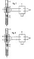
- FIGS. 5 and 6 show the design of the holding device 7 with two protective gas contact switches 5 in order to enable a bistable switching behavior of the device.
- Figure 5 is a longitudinal section comparable to Figure 4 from the front
- Figure 6 is a longitudinal section comparable to Figure 3 from the side.
- FIG. 5 shows the groove 9 for receiving the two protective gas contacts 5 and the longitudinal gap 10 running on the end face of the block 7.
- the cross holes for making the connection wires to the contact switches 5 are shown, their implementation to the rear can be clearly seen in Figure 6.
- 8 denotes the longitudinal bore, which has the longitudinal gap 10 on the front side and the groove on the opposite side.
- FIG. 7 shows the arrangement and circuit for monostable switching behavior of the measuring device according to the invention.
- a medium flows through the measuring tube 3 from bottom to top and the flow lifts the float 4 with the miniature magnet 6 arranged therein.
- the holding device 7 is clamped to the measuring tube 3 in a stroke height corresponding to the desired flow rate.
- the contact protection relay 11 As soon as the float 4 has reached the height of the protective gas contact 5, its contacts are closed by the magnetic force and the contact protection relay 11 is excited. This relay in turn actuates the potential-free switching contact 12 as a relay output.
- a direct or alternating voltage as shown, can be applied to the contact protection relay 11.
- FIG. 8 shows the design for bistable switching behavior with two protective gas contact switches 5 within the block-shaped holding device 7, which is pushed over the measuring tube 3.
- the float 4 although raised by the flow, is still below the switching point. It contains an axially magnetized miniature magnet 6, cemented in.
- Both protective gas contacts so-called reed contacts, are connected to an electronic switching element 13.
- Contact a is connected to the first contact switch and contact b is connected to the second contact switch.
- the electronic switching element 13 is supplied with a control pulse which resets the switching element or leads to the zero position.
- the measuring body 4 reaches the second protective gas contact 5 and triggers a second signal in the electronic switching element. This switches the potential-free contact 12.
- the electronic switching element is designed so that this state is maintained until the electronic switching element is returned to the zero position by actuation of the first contact.
- the electronic switching element is supplied with a suitable voltage from a direct voltage or alternating current source.
- the contacts 12 of the switching element are designed as a potential-free switching contact.
- Figure 9 shows the float 4 in longitudinal section with the inserted magnet 6. This is inserted into a corresponding bore of the float 4 and secured by a plug 14.
- the float 4 has a cylindrical cross section and is tapered conically at the lower end. At the other end, an extended outer edge is provided for stabilization.
- the float has a diameter of 6 mm and is 10 mm long, the upper edge being 1 mm thick and the conical piece 5 mm long.
- the float 4 can also have a cylindrical cross section, each with an enlarged outer edge at both ends for stabilization. Such shapes are preferred if the magnet is only provided with a protective coating made of plastic.
- the encapsulated magnet in the case shown has a diameter of 3 mm and is 3 mm long.
- the magnetization of the magnets is axial in order to be able to exert a force on the protective gas contacts on the side in the assembled state.
- the measuring tube provided with a scale is not inserted into a special frame, but instead has ends for line connections, the cross section of the floating body being only slightly changing at the ends of the measuring body at both ends of the measuring section.
- the block-shaped holding device is pushed onto the measuring tube. It is longitudinally displaceable and encompasses the measuring tube like a spring clip due to the elastic properties of the plastic block.
- the measuring tube and the block are connected to one another in a suitable manner, for example by common arrangement within a housing or frame or by holding clips. This attachment fixes the position of the protective gas contact switch or the two switches on the measuring tube.
- a longitudinally displaceable design for the holding block is also possible with this design.
Landscapes
- Physics & Mathematics (AREA)
- Fluid Mechanics (AREA)
- General Physics & Mathematics (AREA)
- Measuring Volume Flow (AREA)
- Level Indicators Using A Float (AREA)
- Measurement Of Current Or Voltage (AREA)
Claims (10)
Priority Applications (1)
| Application Number | Priority Date | Filing Date | Title |
|---|---|---|---|
| AT83104534T ATE22617T1 (de) | 1982-08-11 | 1983-05-09 | Vorrichtung zur durchflussmessung mit potentialfreiem endkontaktschalter. |
Applications Claiming Priority (2)
| Application Number | Priority Date | Filing Date | Title |
|---|---|---|---|
| DE8222641U | 1982-08-11 | ||
| DE19828222641U DE8222641U1 (de) | 1982-08-11 | 1982-08-11 | Vorrichtung zur durchflussmessung mit potentialfreiem endkontaktschalter |
Publications (2)
| Publication Number | Publication Date |
|---|---|
| EP0101532A1 EP0101532A1 (fr) | 1984-02-29 |
| EP0101532B1 true EP0101532B1 (fr) | 1986-10-01 |
Family
ID=6742661
Family Applications (1)
| Application Number | Title | Priority Date | Filing Date |
|---|---|---|---|
| EP83104534A Expired EP0101532B1 (fr) | 1982-08-11 | 1983-05-09 | Débitmètre avec interrupteur de contact de fin de course, libre de potentiel |
Country Status (4)
| Country | Link |
|---|---|
| US (1) | US4611105A (fr) |
| EP (1) | EP0101532B1 (fr) |
| AT (1) | ATE22617T1 (fr) |
| DE (2) | DE8222641U1 (fr) |
Families Citing this family (8)
| Publication number | Priority date | Publication date | Assignee | Title |
|---|---|---|---|---|
| DE8710768U1 (de) * | 1987-08-06 | 1987-09-24 | Meister Strömungstechnik GmbH, 6464 Linsengericht | Schwebekörperdurchflußmesser |
| US5327789A (en) * | 1992-04-03 | 1994-07-12 | Rosemount, Inc. | Electromagnetic detection system for variable area flowmeter |
| DE19620699C1 (de) * | 1996-05-23 | 1997-11-20 | Hanno Dipl Ing Schmitz | Strömungswächter mit Warnvorrichtung |
| US6214239B1 (en) * | 1996-12-09 | 2001-04-10 | Renau Corporation | Water filter usage monitoring apparatus |
| RU2137093C1 (ru) * | 1997-02-05 | 1999-09-10 | Российский Федеральный Ядерный Центр - Всероссийский Научно-Исследовательский Институт Экспериментальной Физики | Ротаметр |
| ITMI20010632A1 (it) | 2001-03-23 | 2002-09-23 | Pettinaroli Flii Spa | Misuratore ottico di portata |
| US8627728B2 (en) | 2012-01-31 | 2014-01-14 | Hammonds Technical Services, Inc. | System for determining the flow rate in a fluid with liquid additives using reciprocating positive-displacement flow meter |
| JP2015155845A (ja) * | 2014-02-20 | 2015-08-27 | サーパス工業株式会社 | 差圧式流量計およびそれを備えた流量コントローラ |
Family Cites Families (6)
| Publication number | Priority date | Publication date | Assignee | Title |
|---|---|---|---|---|
| DE1071359B (fr) * | 1959-12-17 | |||
| US3224270A (en) * | 1963-02-12 | 1965-12-21 | Rca Corp | Flow gauges |
| ES431609A1 (es) * | 1974-11-04 | 1976-10-16 | Wenderoth | Sensor magnetico de flujo de fluidos. |
| DE2546303A1 (de) * | 1975-10-16 | 1977-04-21 | Willi Tiefenbach | Vorrichtung zur durchflussmessung von fluessigkeiten |
| GB1604247A (en) * | 1978-05-26 | 1981-12-02 | Morgan G | Switch assembly responsive to fluid flow |
| CA1167132A (fr) * | 1980-10-16 | 1984-05-08 | Aaron V. Farr | Detecteur de vitesse de descente |
-
1982
- 1982-08-11 DE DE19828222641U patent/DE8222641U1/de not_active Expired
-
1983
- 1983-05-09 EP EP83104534A patent/EP0101532B1/fr not_active Expired
- 1983-05-09 AT AT83104534T patent/ATE22617T1/de not_active IP Right Cessation
- 1983-05-09 DE DE8383104534T patent/DE3366543D1/de not_active Expired
-
1985
- 1985-08-08 US US06/763,632 patent/US4611105A/en not_active Expired - Lifetime
Non-Patent Citations (1)
| Title |
|---|
| E. BARTHOLOME et al. "Ullmanns Encyklopädie der technischen Chemie", 4. Auflage, Band 16, 1978, VER LAG CHEMIE, Weinheim, New York, Seiten 386-395 * |
Also Published As
| Publication number | Publication date |
|---|---|
| DE8222641U1 (de) | 1982-11-18 |
| ATE22617T1 (de) | 1986-10-15 |
| US4611105A (en) | 1986-09-09 |
| EP0101532A1 (fr) | 1984-02-29 |
| DE3366543D1 (en) | 1986-11-06 |
Similar Documents
| Publication | Publication Date | Title |
|---|---|---|
| EP0101532B1 (fr) | Débitmètre avec interrupteur de contact de fin de course, libre de potentiel | |
| DE1175745B (de) | Elektromagnetischer Wandler | |
| DE2826247A1 (de) | Kurzschlussanzeiger fuer elektrische leitungen | |
| DE3447312A1 (de) | Magnetfeldsensor | |
| DE1909940B2 (de) | Elektromagnetisches umschaltrelais mit geschuetztem kontakt system | |
| DE4303403A1 (en) | Linear displacement position detector - has encapsulated magnetoresistive sensor element in electromagnetically screened chamber with bar magnet activation | |
| DE1243271B (de) | Elektromagnetisches Umschaltrelais mit geschuetztem Kontaktsystem | |
| DE4107279C1 (fr) | ||
| DE3628400A1 (de) | Kurzschlussanzeiger | |
| DE10119939A1 (de) | Magnetspulenanordnung | |
| EP0438616A1 (fr) | Transformateur courant-tension pour des compteurs domestiques électroniques | |
| DE3401488C1 (de) | Meßsonde | |
| DE8226199U1 (de) | Vorrichtung zur durchflussmessung von fluessigkeiten und gasstroemen | |
| DE7427261U (de) | Berührungsloser Magnetschalter | |
| DE3329309C2 (de) | Bistabiles elektromagnetisches Anzeigeelement | |
| DE2913813A1 (de) | Leckfuehler fuer ein elektronisches fluessigkeits-leckueberwachungsgeraet | |
| AT281973B (de) | Haftrelais | |
| DE3940280A1 (de) | Vorrichtung zur ermittlung der durchflussmenge eines stroemungsmediums | |
| AT244429B (de) | Schutzrohrankerkontaktanordnung mit einem Ferritelement | |
| DE3022863A1 (de) | Fuellstandmessgeraet fuer fluessigkeitsbehaelter | |
| DE2155836C3 (de) | Neigungsmeßgerät, insbesondere Zimmerrrtanns-Waage, mit Signalgebung durch Kontaktschluß mittels schwerkraftorientierten Körpers | |
| AT234199B (de) | Schutzrohrkontaktanordnung mit einem Ferrit-Element | |
| AT280399B (de) | Haftrelais mit in einer hermetisch verschlossenen Glasröhre befindlichen Kontaktzungen aus einem Material mit mehreren Remanenzzuständen | |
| DE3435910A1 (de) | Magnetisch-induktiver durchflussmesser mit auswechselbaren durchflusssensoren | |
| AT206487B (de) | Relais mit in Schutzrohren angeordneten Ankerkontakten |
Legal Events
| Date | Code | Title | Description |
|---|---|---|---|
| PUAI | Public reference made under article 153(3) epc to a published international application that has entered the european phase |
Free format text: ORIGINAL CODE: 0009012 |
|
| AK | Designated contracting states |
Designated state(s): AT BE CH DE FR GB LI NL |
|
| 17P | Request for examination filed |
Effective date: 19840307 |
|
| GRAA | (expected) grant |
Free format text: ORIGINAL CODE: 0009210 |
|
| AK | Designated contracting states |
Kind code of ref document: B1 Designated state(s): AT BE CH DE FR GB LI NL |
|
| REF | Corresponds to: |
Ref document number: 22617 Country of ref document: AT Date of ref document: 19861015 Kind code of ref document: T |
|
| REF | Corresponds to: |
Ref document number: 3366543 Country of ref document: DE Date of ref document: 19861106 |
|
| ET | Fr: translation filed | ||
| PLBE | No opposition filed within time limit |
Free format text: ORIGINAL CODE: 0009261 |
|
| STAA | Information on the status of an ep patent application or granted ep patent |
Free format text: STATUS: NO OPPOSITION FILED WITHIN TIME LIMIT |
|
| 26N | No opposition filed | ||
| REG | Reference to a national code |
Ref country code: GB Ref legal event code: IF02 |
|
| PGFP | Annual fee paid to national office [announced via postgrant information from national office to epo] |
Ref country code: GB Payment date: 20020415 Year of fee payment: 20 |
|
| PGFP | Annual fee paid to national office [announced via postgrant information from national office to epo] |
Ref country code: NL Payment date: 20020517 Year of fee payment: 20 Ref country code: FR Payment date: 20020517 Year of fee payment: 20 |
|
| PGFP | Annual fee paid to national office [announced via postgrant information from national office to epo] |
Ref country code: AT Payment date: 20020523 Year of fee payment: 20 |
|
| PGFP | Annual fee paid to national office [announced via postgrant information from national office to epo] |
Ref country code: CH Payment date: 20020524 Year of fee payment: 20 Ref country code: BE Payment date: 20020524 Year of fee payment: 20 |
|
| PGFP | Annual fee paid to national office [announced via postgrant information from national office to epo] |
Ref country code: DE Payment date: 20020724 Year of fee payment: 20 |
|
| PG25 | Lapsed in a contracting state [announced via postgrant information from national office to epo] |
Ref country code: LI Free format text: LAPSE BECAUSE OF EXPIRATION OF PROTECTION Effective date: 20030508 Ref country code: GB Free format text: LAPSE BECAUSE OF EXPIRATION OF PROTECTION Effective date: 20030508 Ref country code: CH Free format text: LAPSE BECAUSE OF EXPIRATION OF PROTECTION Effective date: 20030508 |
|
| PG25 | Lapsed in a contracting state [announced via postgrant information from national office to epo] |
Ref country code: NL Free format text: LAPSE BECAUSE OF EXPIRATION OF PROTECTION Effective date: 20030509 Ref country code: AT Free format text: LAPSE BECAUSE OF EXPIRATION OF PROTECTION Effective date: 20030509 |
|
| REG | Reference to a national code |
Ref country code: GB Ref legal event code: PE20 |
|
| REG | Reference to a national code |
Ref country code: CH Ref legal event code: PL |
|
| BE20 | Be: patent expired |
Owner name: *KOBOLD KLAUS Effective date: 20030509 |
|
| NLV7 | Nl: ceased due to reaching the maximum lifetime of a patent |
Effective date: 20030509 |