EP0101558A2 - Multi-coordinate feeler head - Google Patents
Multi-coordinate feeler head Download PDFInfo
- Publication number
- EP0101558A2 EP0101558A2 EP83106949A EP83106949A EP0101558A2 EP 0101558 A2 EP0101558 A2 EP 0101558A2 EP 83106949 A EP83106949 A EP 83106949A EP 83106949 A EP83106949 A EP 83106949A EP 0101558 A2 EP0101558 A2 EP 0101558A2
- Authority
- EP
- European Patent Office
- Prior art keywords
- stylus
- probe
- probe according
- coordinate
- protected multi
- Prior art date
- Legal status (The legal status is an assumption and is not a legal conclusion. Google has not performed a legal analysis and makes no representation as to the accuracy of the status listed.)
- Granted
Links
- 239000000523 sample Substances 0.000 claims abstract description 60
- 241001422033 Thestylus Species 0.000 claims abstract description 31
- 230000003287 optical effect Effects 0.000 claims description 4
- 230000005540 biological transmission Effects 0.000 claims 1
- 238000003754 machining Methods 0.000 description 2
- 238000004519 manufacturing process Methods 0.000 description 2
- 238000005259 measurement Methods 0.000 description 2
- 238000000034 method Methods 0.000 description 2
- 230000002950 deficient Effects 0.000 description 1
- 230000007257 malfunction Effects 0.000 description 1
- 230000000284 resting effect Effects 0.000 description 1
- 238000000926 separation method Methods 0.000 description 1
- 238000003860 storage Methods 0.000 description 1
- 239000000725 suspension Substances 0.000 description 1
Images


Classifications
-
- G—PHYSICS
- G01—MEASURING; TESTING
- G01B—MEASURING LENGTH, THICKNESS OR SIMILAR LINEAR DIMENSIONS; MEASURING ANGLES; MEASURING AREAS; MEASURING IRREGULARITIES OF SURFACES OR CONTOURS
- G01B5/00—Measuring arrangements characterised by the use of mechanical techniques
- G01B5/004—Measuring arrangements characterised by the use of mechanical techniques for measuring coordinates of points
- G01B5/008—Measuring arrangements characterised by the use of mechanical techniques for measuring coordinates of points using coordinate measuring machines
- G01B5/012—Contact-making feeler heads therefor
-
- G—PHYSICS
- G01—MEASURING; TESTING
- G01B—MEASURING LENGTH, THICKNESS OR SIMILAR LINEAR DIMENSIONS; MEASURING ANGLES; MEASURING AREAS; MEASURING IRREGULARITIES OF SURFACES OR CONTOURS
- G01B7/00—Measuring arrangements characterised by the use of electric or magnetic techniques
- G01B7/002—Constructional details of contacts for gauges actuating one or more contacts
Definitions
- the invention relates to a multi-coordinate probe according to the preamble of claim 1.
- Multi-coordinate probes of various types are known from a large number of publications.
- S o is an electronic multi-coordinate probe
- the stylus is known from DE-PS 22 42 355. disposed at a spatial Gerad Entryssystem and has signal transmitters, which emit a signal when stylus deflection.
- DE-OS 15 48 326 a zero touch device for machine tools is known, in which an overload protection is provided, which enables a separation of the holder and measuring device in the event of an overload.
- the invention is therefore based on the object to provide a multi-coordinate probe which does not have the known disadvantages, and which therefore takes into account the rough requirements of use in workshops as well as use in automatically controlled production processes and use in multi-coordinate measuring machines .
- the multi-coordinate probe should therefore provide a precisely reproducible probe signal, be robust and offer security in the case of faulty measurement processes without the probe being destroyed.
- the particular advantages of the probe head according to the invention lie in the safety compared to casual stylus deflection, in the good reproducibility of the stylus deflection signal, in the small size and the relatively on. fold structure.
- a probe head shown in FIG. 1 in its basic working position has a probe head housing 1, which can be inserted into the spindle of a measuring or processing machine (not shown) by means of a clamping pin 2. If this machine is a numerically controlled machining center, the probe can be stored in the tool magazine and automatically removed for measuring purposes and inserted into the spindle.
- a substantially round plate 3 is arranged, which is attached to the inner end of a stylus 4-, which is at its free End a probe ball 5 carries.
- the plate 3 has a precisely defined position relative to a ring of balls 6, which are cemented onto the bottom 7 of the probe housing 1, distributed uniformly over the circumference of a stylus passage opening 8.
- the ring of balls 6 forms a precise support for the plate 3, which for this purpose (for resting on the ring of balls 6) has a rotationally symmetrical recess 9 which forms a flat and a curved, for example conical surface, or two conical surfaces , with the help of which the balls 6 embedded in the still soft putty are pressed into a precise position with regard to the height and diameter of the ring of balls 6 and held there until the putty has hardened.
- a very precise overlay is created for the plate 3 which is inexpensive, and would hardly be targeted with this precision by machining the bottom 7 to it. 7
- An unspecified anti-rotation device ensures that the plate 3 with the stylus 4 always returns to the starting position after deflections. Due to the exact position of the plate 3 in relation to the ring of balls 6, the zero position of the probe ball 5 is always exactly the same (of course within the required tolerances).
- the stylus 4 is connected to the probe housing 1 via an articulated gear.
- the stylus 4 represents the input gear member, which is gimbally connected to an intermediate member 10 by means of the joint 11.
- the intermediate member 10 has at the other end another cardan joint 12 with which it is attached to a pivot lever 13.
- the pivot lever 13 forms the output member of the articulated gear and is articulated on the probe housing 1 by means of a flat articulation 14.
- a photoelectric unit 16 at the free end of the pivot lever 13 serves to generate a stylus deflection signal when the stylus 4 has been deflected in any direction.
- the working range of such a probe is within 1 to 2 millimeters, which means that in general the generation of a stylus deflection signal is safely completed at the latest after a deflection of 10 micrometers (10 gm) in order to ensure the required reproducibility during the measurements.
- the stylus deflection generally takes place in that a workpiece W is brought into contact with the stylus 4.
- the stylus deflection signal then serves to fix the measured value upon contact between stylus 4 and workpiece W and can be evaluated by the numerical control to stop the machine components which are movable relative to one another. It can be seen that with the above-described working range of only a few millimeters, stopping the machine components is problematic becomes table. Therefore, most known probes have a certain overstroke of about 5 mm, so that in this deflection area of the stylus 4 it is not damaged.
- the suspension of the stylus 4 is a novelty, because if the stylus 4 is improperly deflected, it can be completely retracted into the probe housing 1, as can be seen from FIGS. 2, 3 and 4. It does not matter from which direction the workpiece W contacts the stylus 4.
- the articulated gear or the stylus 4 migrates in accordance with the probing movement and pivots the pivot lever 13 in one plane around the axis of the joint 14.
- the intermediate member 10 assumes a position which is determined by the deflection of the stylus 4 and the pivoting of the pivot lever 13 is.
- the restoring force of a spring 15 counteracts the deflection.
- the photoelectric unit 16 generates a signal as soon as the pivot lever 13 moves slightly out of its rest position, which is due to the least contact between workpiece W and stylus 4 is effected.
- the stylus 4 When the stylus 4 is radially deflected, it tilts over at least one of the balls 6, as can be seen from FIG.
- an alarm device 20 can advantageously be provided. This can consist of a microswitch 20 with a long release lever 21 which engages on the pivot lever 13 and which triggers the microswitch 20 as soon as a presettable pivoting of the pivot lever 13 is reached. A further deflection of the swivel lever 13 is irrelevant to the switching behavior of the microswitch 20.
- the alarm signal output by the alarm device 20 can be optical and / or acoustic or can also cause an immediate "emergency stop" for the machine. Manual intervention in the workflow is always required after an alarm.
- the probe can be designed so that a device is provided with the help of which Stylus 4 - in the event of a deflection beyond the working area - is snapped into the interior of the probe housing 1.
- the articulated gear 4, 10, 11, 12, 13, 14 and the spring 15 can be arranged so that after the Snapping the stylus 4 into the interior of the probe housing 1 results in a locking of the stylus 4 in the interior of the probe housing 1.
- the locking can take place by the resultant of the force components of the spring 15 (FIG. 4), but a mechanical or electromechanical locking, for example with a controllable locking lever, is also possible.
- the lock can then be released again during manual intervention.
- the advantages of the invention can also be used during transport and storage of the probe, since in these cases the stylus 4 can be sunk into the interior of the probe housing 1.
- the stylus passage opening 8 can then advantageously be closed with a cap.
- the assembly 16 for generating the stylus deflection signal can also work inductively, capacitively or magnetically.
Landscapes
- Physics & Mathematics (AREA)
- General Physics & Mathematics (AREA)
- A Measuring Device Byusing Mechanical Method (AREA)
- Length Measuring Devices With Unspecified Measuring Means (AREA)
- Magnetic Resonance Imaging Apparatus (AREA)
- Apparatus For Radiation Diagnosis (AREA)
- Measurement Of Length, Angles, Or The Like Using Electric Or Magnetic Means (AREA)
Abstract
Der Tastkopf weist ein Tastkopfgehäuse (1) auf, in dem ein Gelenkgetriebe (4, 10, 11, 12, 13, 14) angeordnet ist, das ermöglicht, daß der Taststift (4) bei Auslenkung in eine beliebige Richtung vollständig in das Tastkopfgehäuse (1) eintauchen kann. Dadurch ist weitestgehender Schutz vor Beschädigung des Taststiftes (4) im Störungsfall gegeben.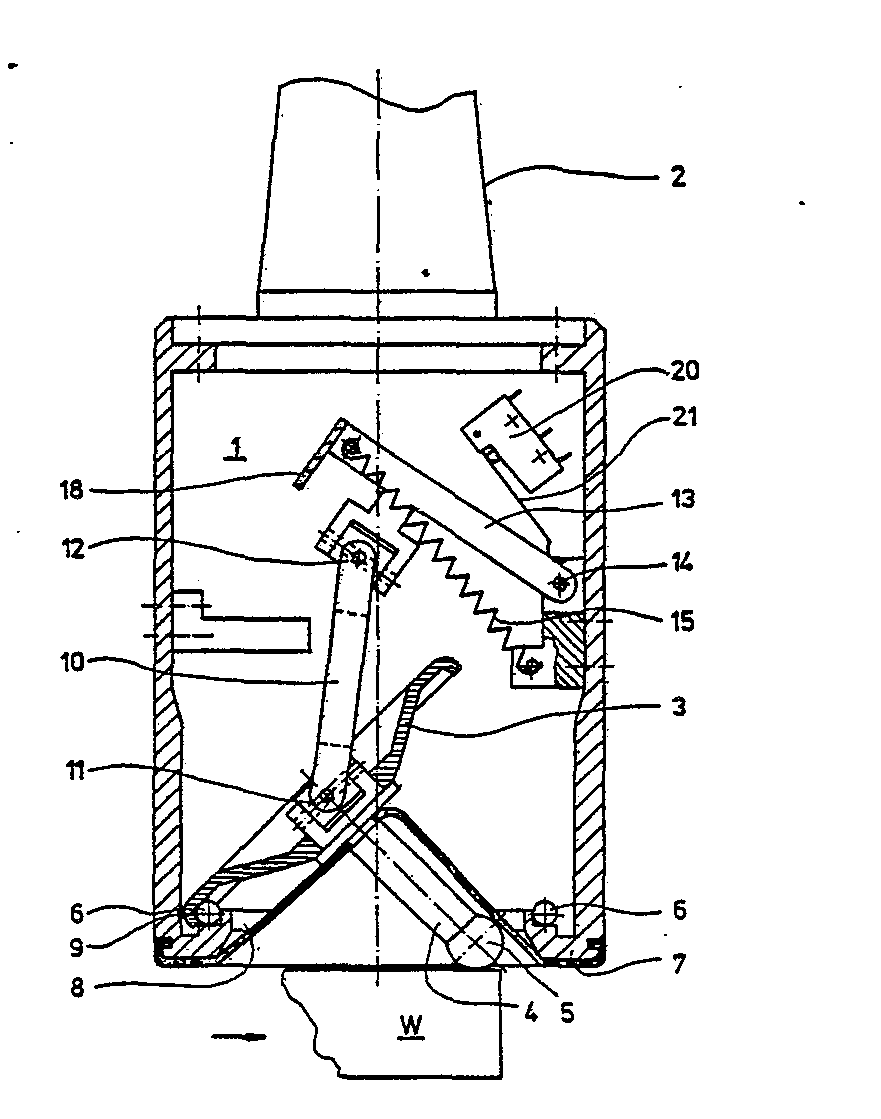
Description
Die Erfindung bezieht sich auf einen Mehrkoordinaten-Tastkopf gemäß dem Oberbegriff des Anspruches 1.The invention relates to a multi-coordinate probe according to the preamble of
Aus einer Vielzahl von Druckschriften sind Mehrkoordinaten-Tastköpfe der unterschiedlichsten Bauarten bekannt.Multi-coordinate probes of various types are known from a large number of publications.
So ist aus der DE-PS 22 42 355 ein elektronischer Mehrkoordinatentaster bekannt, dessen Taststift an einem räumlichen Geradführungssystem angeordnet ist und über Signalgeber verfügt, die bei Auslenkung des Taststiftes ein Signal abgeben. S o is an electronic multi-coordinate probe, the stylus is known from DE-PS 22 42 355. disposed at a spatial Geradführungssystem and has signal transmitters, which emit a signal when stylus deflection.
Ferner ist aus der DE-OS 15 48 326 eine Null-Tasteinrichtung für Werkzeugmaschinen bekannt, bei der eine Überlastsicherung vorgesehen ist, die beim Überlastungsfall eine Trennung von Halterung und Meßgerät ermöglicht.Furthermore, from DE-OS 15 48 326 a zero touch device for machine tools is known, in which an overload protection is provided, which enables a separation of the holder and measuring device in the event of an overload.
Die hier nur beispielhaft aus der großen Anzahl der relevanten Druckschriften herausgegriffenen Lösungen sind mit Mängeln behaftet, wenn MehrkoordinatenTaster nicht nur an Meßmaschinen, sondern in zunehmendem Maße an numerisch gesteuerten Bearbeitungsmaschinen wie Bearbeitungszentren eingesetzt werden. Der im Gegensatz zu den Verhältnissen im Meßraum recht rauhe Werkstattbetrieb und die weitgehend automatischen Fertigungsabläufe erfordern neuartige Meßeinrichtungen, die nicht ohne weiteres mit den bekannten Lösungen geschaffen werden können.The solutions selected here only as examples from the large number of relevant publications are defective if multi-coordinate buttons are used not only on measuring machines, but increasingly on numerically controlled processing machines such as machining centers. In contrast to the conditions in the measuring room, the workshop operation is rather rough and the largely automatic production processes require novel measuring devices that cannot be easily created with the known solutions.
Der Erfindung liegt daher die Aufgabe zugrunde, einen Mehrkoordinaten-Tastkopf zu schaffen, der die bekannten Nachteile nicht aufweist, der also den rauhen Anforderungen des Einsatzes in Werkstätten ebenso Rechnung trägt wie dem Einsatz bei automatisch gesteuerten Fertigungsabläufen und dem Ein, satz bei Mehrkoordinaten-Meßmaschinen. Der Mehrkoordinaten-Tastkopf sollte also ein genau reproduzierbares Antastsignal liefern, robust sein und Sicherheit bei fehlerhaften Meßabläufen bieten, ohne daß der Meßkopf zerstört wird.The invention is therefore based on the object to provide a multi-coordinate probe which does not have the known disadvantages, and which therefore takes into account the rough requirements of use in workshops as well as use in automatically controlled production processes and use in multi-coordinate measuring machines . The multi-coordinate probe should therefore provide a precisely reproducible probe signal, be robust and offer security in the case of faulty measurement processes without the probe being destroyed.
Diese Aufgabe wird von einem Mehrkoordinaten-Tastkopf gelöst, der durch die Merkmale des Anspruches 1 gekennzeichnet ist.This object is achieved by a multi-coordinate probe, which is characterized by the features of
Weitere Ausgestaltungen der Erfindung sind in den Unteransprüchen angegeben.Further refinements of the invention are specified in the subclaims.
Die besonderen Vorteile des erfindungsgemäßen Tastkopfes liegen in der Sicherheit gegenüber unzulässiger Taststiftauslenkung, in der guten Reproduzierbarkeit des Taststiftauslenkungssignales, in der geringen Baugröße und dem verhältnismäßig ein-. fachen Aufbau.The particular advantages of the probe head according to the invention lie in the safety compared to casual stylus deflection, in the good reproducibility of the stylus deflection signal, in the small size and the relatively on. fold structure.
Anhand der Zeichnungen sollen Ausführungsbeispiele der Erfindung noch näher erläutert werden.Exemplary embodiments of the invention are to be explained in more detail with reference to the drawings.
Es zeigen:
Figur 1 eine Schnittdarstellung eines Tastkopfes in Arbeitsstellung,Figur 2 eine Schnittdarstellung eines Tastkopfes bei axialer Taststiftauslenkung,Figur 3 eine Schnittdarstellung eines Tastkopfes bei radialer Taststiftauslenkung,Figur 4 eine Variante vonFigur 3.
- FIG. 1 shows a sectional illustration of a probe in the working position,
- FIG. 2 shows a sectional illustration of a probe head with axial stylus deflection,
- FIG. 3 shows a sectional illustration of a probe head with radial stylus deflection,
- FIG. 4 shows a variant of FIG. 3.
Ein in Figur 1 gezeigter Tastkopf in seiner Grund-Arbeitsstellung weist ein Tastkopfgehäuse 1 auf, das mittels eines Einspannzapfens 2 in die Spindel einer nicht dargestellten Meß- oder Bearbeitungsmaschine eingesetzt werden kann. Ist diese Maschine ein numerisch gesteuertes Bearbeitungszentrum, so kann der Tastkopf im Werkzeugmagazin deponiert sein und automatisch zu Meßzwecken entnommen und in die Spindel eingesetzt werden. Im Innern des Tastkopfgehäuses 1 ist eine im wesentlichen runde Platte 3 angeordnet, die am inneren Ende eines Taststiftes 4- befestigt ist, der an seinem freien Ende eine Antastkugel 5 trägt. Die Platte 3 hat eine genau definierte Lage zu einem Ring von Kugeln 6, die am Boden 7 des Tastkopfgehäuses 1 - gleichmäßig über den Umfang einer Taststiftdurchtrittsöffnung 8 verteilt - eingekittet sind. Der Ring von Kugeln 6 bildet eine präzise Auflage für die Platte 3, die zu diesem Zweck (zur Auflage auf dem Ring von Kugeln 6) eine rotationssymmetrische Ausnehmung 9 aufweist, die eine ebene und eine gekrümmte, z.B. konische Fläche, oder zwei konische Flächen bildet, mit deren Hilfe die im noch weichen Kitt eingebetteten Kugeln 6 in eine genaue Position bezüglich Höhe und Durchmesser des Ringes von Kugeln 6 gedrückt und dort bis zur Erhärtung des Kittes gehalten werden. Damit wird für die Platte 3 eine äußerst präzise Auflage geschaffen, die preisgünstig ist, und die mit dieser Präzision durch spanende Bearbeitung des Bodens 7 kaum zu er7 zielen wäre.A probe head shown in FIG. 1 in its basic working position has a
Eine nicht näher bezeichnete Verdrehsicherung sorgt dafür, daß die Platte 3 mit dem Taststift 4 nach Auslenkungen immer wieder in die Ausgangsposition zurückkehrt. Durch die axakte Lage der Platte 3 zu dem Ring von Kugeln 6 ist auch die Nullage der Antastkugel 5 immer exakt dieselbe (innerhalb der geforderten Toleranzen selbstverständlich).An unspecified anti-rotation device ensures that the
Der Taststift 4 ist über ein Gelenkgetriebe mit dem Tastkopfgehäuse 1 verbunden. Der Taststift 4 stellt dabei das Eingangsgetriebeglied dar, das mit Hilfe des Gelenkes 11 kardanisch mit einem Zwischenglied 10 verbunden ist. Das Zwischenglied 10 weist am anderen Ende ein weiteres kardanisches Gelenk 12 auf, mit dem es an einem Schwenkhebel 13 angebracht ist. Der Schwenkhebel 13 bildet das Ausgangsglied des Gelenkgetriebes und ist mittels eines ebenen Gelenkes 14 am Tastkopfgehäuse 1 angelenkt.The
Mit einer Feder 15, die am Schwenkhebel 13 angreift, wird der Taststift 4 in seiner Nullage gehalten, aus der er gegen die Rückstellkraft der Feder 15 in beliebiger Richtung auslenkbar ist. Eine lichtelektrische Baueinheit 16 am freien Ende des Schwenkhebels 13 dient zur Erzeugung eines Taststiftauslenksignales, wenn der Taststift 4 in eine beliebige Richtung ausgelenkt worden ist.With a
Üblicherweise liegt der Arbeitsbereich eines derartigen Tastkopfes innerhalb von 1 bis 2 Millimetern das bedeutet, daß im allgemeinen die Erzeugung eines Taststiftauslenksignales spätestens nach einer Auslenkung um 10 Mikrometer (10gm) sicher abgeschlossen ist, um die erforderliche Reproduzierbarkeit bei den Messungen sicherzustellen.Usually, the working range of such a probe is within 1 to 2 millimeters, which means that in general the generation of a stylus deflection signal is safely completed at the latest after a deflection of 10 micrometers (10 gm) in order to ensure the required reproducibility during the measurements.
Die Taststiftauslenkung erfolgt im allgemeinen dadurch, daß ein Werkstück W mit dem Taststift 4 in Kontakt gebracht wird. Das Taststiftauslenksignal dient dann der Fixierung des Meßwertes bei Kontakt zwischen Taststift 4 und Werkstück W und kann zum Stoppen der relativ zueinander beweglichen Maschinenbauteile von der numerischen Steuerung ausgewertet werden. Es ist ersichtlich, daß bei dem vorbeschriebenen Arbeitsbereich von nur wenigen Millimeter das Stoppen der Maschinenbauteile problematisch wird. Daher haben die meisten bekannten Tastköpfe einen gewissen überhub von etwa 5 mm, so daß in diesem Auslenkungsbereich des Taststiftes 4 dieser noch nicht beschädigt wird.The stylus deflection generally takes place in that a workpiece W is brought into contact with the
Bei Störungen, die Steuerungs- oder Antriebs bedingt sind, reicht dieser Überhub unter Umständen nicht aus und es kommt zu Beschädigungen des Tastkopfes. Aus diesen Gründen gibt es auch noch Uberlastsicherungen, die den Tastkopf ausklinken, wenn die Auslenkung des Taststiftes zu groß wird. Wie bereits eingangs erwähnt, sind die bekannten Lösungen mit Nachteilen behaftet.In the event of malfunctions caused by the control or drive, this overstroke may not be sufficient and the probe may be damaged. For these reasons, there are also overload safeguards that release the probe if the deflection of the stylus becomes too great. As already mentioned at the beginning, the known solutions have disadvantages.
Hier stellt die Aufhängung des Taststiftes 4 ein Novum dar, denn bei unsachgemäßer Auslenkung des Taststiftes 4 ist dieser vollständig im Tastkopfgehäuse 1 versenkbar, wie aus den Figuren 2, 3 und 4 ersichtlich ist. Dabei ist es gleichgültig, von welcher Richtung aus das Werkstück W den Taststift 4 kontaktiert. Das Gelenkgetriebe bzw. der Taststift 4 wandert entsprechend der Antastbewegung aus und schwenkt den Schwenkhebel 13 in einer Ebene um die Achse des Gelenkes 14. Das Zwischenglied 10 nimmt dabei eine Lage ein, die durch die Auslenkung des Taststiftes 4 und die Schwenkung des Schwenkhebels 13 bestimmt ist. Die Rückstellkraft einer Feder 15 wirkt der Auslenkung entgegen.Here, the suspension of the
Die lichtelektrische Baueinheit 16 erzeugt ein Signal, sobald sich der Schwenkhebel 13 geringfügig aus seiner Ruhelage heraus bewegt, was durch den geringsten Kontakt zwischen Werkstück W und Taststift 4 bewirkt wird. Beim radialen Auslenken des Taststiftes 4 kippt dieser über wenigstens eine der Kugeln 6, wie aus Figur 3 ersichtlich ist.The
Da ein Auslenken aus dem Arbeitsbereich heraus (ca. 5 mm) immer auf eine Störung hindeutet, kann in vorteilhafter Weise eine Alarmvorrichtung 20 vorgesehen sein. Diese kann aus einem Mikroschalter 20 mit einem langen Auslösehebel 21 bestehen, der am Schwenkhebel 13 angreift und der den Mikroschalter 20 auslöst, sobald eine voreinstellbare Schwenkung des Schwenkhebels 13 erreicht ist. Eine weitere Auslenkung des Schwenkhebels 13 ist ohne Bedeutung auf das Schaltverhalten des Mikroschalters 20. Das von der Alarmvorrichtung 20 ausgegebene Alarmsignal kann optisch und/oder akkustisch sein oder auch ein sofortiges "Not-Aus" für die Maschine bewirken. Ein manueller Eingriff in den Arbeitsablauf ist in jedem Fall nach einem Alarm erforderlich.Since deflection out of the working area (approx. 5 mm) always indicates a fault, an
Dieser manuelle Eingriff nach einer Störsituation läßt auch eine weitere Ausgestaltung des Tastkopfes zu: Wenn nach einem Störfall ein manueller Eingriff - in den im übrigen automatischen Ablauf - notwendig ist, kann der Tastkopf so konzipiert werden, daß eine Vorrichtung vorgesehen wird, mit deren Hilfe der Taststift 4 - bei einer Auslenkung über den Arbeitsbereich hinaus - ins Innere des Tastkopfgehäuses 1 geschnappt wird. Das Gelenkgetriebe 4, 10, 11, 12, 13, 14 und die Feder 15 können dabei so angeordnet sein, daß sich nach dem Einschnappen des Taststiftes 4 ins Innere des Tastkopfgehäuses 1 eine Arretierung des Taststiftes 4 , im Innern des Tastkopfgehäuses 1 ergibt. Die Arretierung kann dabei durch die Resultierende der Kraftkomponenten der Feder 15 erfolgen (Fig. 4), aber es ist auch eine mechanische oder elektromechanische Arretierung, beispielsweise mit einem ansteuerbaren Sperrhebel möglich. Bei dem manuellen Eingriff kann dann die Verriegelung wieder gelöst werden.This manual intervention after a fault situation also allows a further design of the probe: If a manual intervention - in the rest of the automatic process - is necessary after an accident, the probe can be designed so that a device is provided with the help of which Stylus 4 - in the event of a deflection beyond the working area - is snapped into the interior of the
Die Vorteile der Erfindung lassen sich auch beim Transport und bei der Lagerung des Tastkopfes nutzbar machen, da auch in diesen Fällen der Taststift 4 ins Innere des Tastkopfgehäuses 1 versenkt werden kann. Die Taststiftdurchtritts- öffnung 8 kann in vorteilhafter Weise dann mit einer Kappe verschlossen werden.The advantages of the invention can also be used during transport and storage of the probe, since in these cases the
Es liegt im Rahmen der Erfindung, den Taststift 4 in anderer Weise zu lagern, oder das Gelenkgetriebe anders zu gestalten. Die Baueinheit 16 zur Erzeugung des Taststiftauslenksignals kann ebenso induktiv, kapazitiv oder magnetisch arbeiten.It is within the scope of the invention to store the
Claims (14)
Priority Applications (1)
| Application Number | Priority Date | Filing Date | Title |
|---|---|---|---|
| AT83106949T ATE35316T1 (en) | 1982-08-21 | 1983-07-15 | MULTI-COORDINATE PROBE. |
Applications Claiming Priority (2)
| Application Number | Priority Date | Filing Date | Title |
|---|---|---|---|
| DE3231158A DE3231158C2 (en) | 1982-08-21 | 1982-08-21 | Multi-coordinate probe |
| DE3231158 | 1982-08-21 |
Publications (3)
| Publication Number | Publication Date |
|---|---|
| EP0101558A2 true EP0101558A2 (en) | 1984-02-29 |
| EP0101558A3 EP0101558A3 (en) | 1985-10-09 |
| EP0101558B1 EP0101558B1 (en) | 1988-06-22 |
Family
ID=6171408
Family Applications (1)
| Application Number | Title | Priority Date | Filing Date |
|---|---|---|---|
| EP83106949A Expired EP0101558B1 (en) | 1982-08-21 | 1983-07-15 | Multi-coordinate feeler head |
Country Status (5)
| Country | Link |
|---|---|
| US (1) | US4547772A (en) |
| EP (1) | EP0101558B1 (en) |
| JP (1) | JPS5960205A (en) |
| AT (1) | ATE35316T1 (en) |
| DE (2) | DE3231158C2 (en) |
Cited By (2)
| Publication number | Priority date | Publication date | Assignee | Title |
|---|---|---|---|---|
| EP0194386A3 (en) * | 1985-01-17 | 1988-10-12 | Emi Limited | Control system for a robotic gripper |
| EP1364769A2 (en) | 2002-05-24 | 2003-11-26 | KALLFASS VERPACKUNGSMASCHINEN GmbH & Co. | Apparatus for working webs |
Families Citing this family (11)
| Publication number | Priority date | Publication date | Assignee | Title |
|---|---|---|---|---|
| CH664216A5 (en) * | 1985-10-14 | 1988-02-15 | Tesa Sa | PROBE DEVICE FOR A MEASURING MACHINE FOR CONDUCTIVE PARTS MOUNTED ON A MEASURING TABLE. |
| DE3701730A1 (en) * | 1987-01-22 | 1988-08-04 | Haff & Schneider | Sensory measuring device |
| DE19631306C2 (en) * | 1996-08-02 | 2001-06-28 | Wolfgang Madlener | Laser light barrier system for tool and workpiece measurement |
| US6114690A (en) * | 1998-01-23 | 2000-09-05 | Penn Engineering & Manufacturing Corp. | Light-controlled safety switch for a punch press |
| US5991704A (en) * | 1998-03-26 | 1999-11-23 | Chrysler Corporation | Flexible support with indicator device |
| DE19929557B4 (en) | 1999-06-18 | 2006-01-19 | Dr. Johannes Heidenhain Gmbh | Method and circuit for setting a switching threshold of a key switch |
| DE19937204C1 (en) * | 1999-07-08 | 2001-02-01 | Mahr Gmbh | Modular mechanical measuring sensor has sensor element displaced by contact with workpiece relative to housing body with intermediate sealing element acting as spring providing spring bias for sensor element |
| RU2267091C2 (en) * | 2003-10-10 | 2005-12-27 | Волгоградский государственный архитектурно-строительный университет (ВолгГАСУ) | Linkage meter |
| JP4963182B2 (en) * | 2006-02-23 | 2012-06-27 | ヤマザキマザック株式会社 | Pipe seam detection device for 3D laser processing machine |
| EP1870914A2 (en) * | 2006-06-22 | 2007-12-26 | ZIMM Maschinenelemente GmbH + Co | Limit switch with a switching part |
| EP1965493B1 (en) * | 2007-02-28 | 2010-04-14 | Siemens Aktiengesellschaft | Switching device with a coupling element |
Family Cites Families (11)
| Publication number | Priority date | Publication date | Assignee | Title |
|---|---|---|---|---|
| DE506115C (en) * | 1928-05-17 | 1930-09-01 | Fritz Werner Akt Ges | Flexible copier pen |
| DE1028792B (en) * | 1957-06-24 | 1958-04-24 | Zeiss Jena Veb Carl | Button for measuring and testing devices |
| DE1548326A1 (en) * | 1966-02-04 | 1970-07-02 | Erhard Staedele | Zero touch device for machine tools |
| US3571934A (en) * | 1968-06-24 | 1971-03-23 | Lockheed Aircraft Corp | Three-axis inspection probe |
| DE2242355C2 (en) * | 1972-08-29 | 1974-10-17 | Fa. Carl Zeiss, 7920 Heidenheim | Electronic multi-coordinate probe |
| GB1597842A (en) * | 1977-02-07 | 1981-09-09 | Rolls Royce | Indexing mechanism |
| DE2712181C3 (en) * | 1977-03-19 | 1981-01-22 | Fa. Carl Zeiss, 7920 Heidenheim | Touch probe |
| GB1599758A (en) * | 1978-02-10 | 1981-10-07 | Lk Tool Co Ltd | Measuring machine |
| US4213244A (en) * | 1978-05-08 | 1980-07-22 | The Bendix Corporation | Coordinate measuring machine having a failsafe protection system |
| JPS5513881A (en) * | 1978-07-17 | 1980-01-31 | Sony Corp | Position detector |
| DE7900134U1 (en) * | 1979-01-04 | 1979-04-26 | Schnabel, Walter, 7141 Schwieberdingen | WICK CARRIER |
-
1982
- 1982-08-21 DE DE3231158A patent/DE3231158C2/en not_active Expired
-
1983
- 1983-07-15 AT AT83106949T patent/ATE35316T1/en not_active IP Right Cessation
- 1983-07-15 DE DE8383106949T patent/DE3377158D1/en not_active Expired
- 1983-07-15 EP EP83106949A patent/EP0101558B1/en not_active Expired
- 1983-08-11 US US06/522,407 patent/US4547772A/en not_active Expired - Fee Related
- 1983-08-18 JP JP58149718A patent/JPS5960205A/en active Granted
Cited By (2)
| Publication number | Priority date | Publication date | Assignee | Title |
|---|---|---|---|---|
| EP0194386A3 (en) * | 1985-01-17 | 1988-10-12 | Emi Limited | Control system for a robotic gripper |
| EP1364769A2 (en) | 2002-05-24 | 2003-11-26 | KALLFASS VERPACKUNGSMASCHINEN GmbH & Co. | Apparatus for working webs |
Also Published As
| Publication number | Publication date |
|---|---|
| JPS5960205A (en) | 1984-04-06 |
| DE3231158C2 (en) | 1985-11-14 |
| JPH0410566B2 (en) | 1992-02-25 |
| ATE35316T1 (en) | 1988-07-15 |
| DE3231158A1 (en) | 1984-02-23 |
| EP0101558A3 (en) | 1985-10-09 |
| US4547772A (en) | 1985-10-15 |
| EP0101558B1 (en) | 1988-06-22 |
| DE3377158D1 (en) | 1988-07-28 |
Similar Documents
| Publication | Publication Date | Title |
|---|---|---|
| DE3619236C2 (en) | Device for automatically changing measuring tools in a measuring robot or a measuring machine | |
| EP0101558B1 (en) | Multi-coordinate feeler head | |
| EP0332575B1 (en) | Feeler for producing measured value by touching a work piece | |
| EP1554080B1 (en) | Tool holding device and method for positioning a tool | |
| DE2516858C2 (en) | Detachable plug connection for optical fibers | |
| DE1932010B2 (en) | ||
| EP2356401A1 (en) | Optical sensor element for a measuring machine, and coupling element therefor on the measuring machine side | |
| DE3011002A1 (en) | TOOL CONNECTING MECHANISM FOR MACHINE TOOLS | |
| EP2705331A1 (en) | Measuring head for a coordinate measuring device for determining spatial coordinates on a test object | |
| DE3345653C2 (en) | ||
| DE102015226387A1 (en) | Method for carrying out measurements with a test element in a coordinate measuring machine or a machine tool | |
| DE3824549A1 (en) | STORAGE FOR PROBE HEADS | |
| EP2841873A1 (en) | Sensor element for a measuring machine, in particular a coordinate measuring machine | |
| DE102016005699B3 (en) | Method for calibrating a measuring device for measuring body parts and other workpieces and measuring device suitable for carrying out the method | |
| EP0163070B1 (en) | Tooth measuring pin | |
| DE102004018968A1 (en) | Method and measuring device for measuring tools | |
| EP0471168A2 (en) | Support for the feeler of a coordinate measuring machine | |
| CH465245A (en) | Zero touch device for machine tools | |
| EP0280777A1 (en) | Multi-directional touch probe | |
| DE602004004661T2 (en) | DEVICE AND METHOD FOR POSITION CHECKING OF A MECHANICAL PART | |
| DE8223630U1 (en) | Multi-coordinate probe | |
| EP1722189B1 (en) | Feeler and measuring system equipped therewith | |
| EP0144624A2 (en) | Probe and/or measuring device | |
| DE102007013916B4 (en) | Contour measuring device | |
| DE102018106468A1 (en) | Method for centering an optical element in an optical system for an endoscope |
Legal Events
| Date | Code | Title | Description |
|---|---|---|---|
| PUAI | Public reference made under article 153(3) epc to a published international application that has entered the european phase |
Free format text: ORIGINAL CODE: 0009012 |
|
| 17P | Request for examination filed |
Effective date: 19830723 |
|
| AK | Designated contracting states |
Designated state(s): AT CH DE FR GB IT LI NL SE |
|
| PUAL | Search report despatched |
Free format text: ORIGINAL CODE: 0009013 |
|
| AK | Designated contracting states |
Designated state(s): AT CH DE FR GB IT LI NL SE |
|
| 17Q | First examination report despatched |
Effective date: 19870116 |
|
| ITF | It: translation for a ep patent filed | ||
| GRAA | (expected) grant |
Free format text: ORIGINAL CODE: 0009210 |
|
| AK | Designated contracting states |
Kind code of ref document: B1 Designated state(s): AT CH DE FR GB IT LI NL SE |
|
| REF | Corresponds to: |
Ref document number: 35316 Country of ref document: AT Date of ref document: 19880715 Kind code of ref document: T |
|
| GBT | Gb: translation of ep patent filed (gb section 77(6)(a)/1977) | ||
| REF | Corresponds to: |
Ref document number: 3377158 Country of ref document: DE Date of ref document: 19880728 |
|
| ET | Fr: translation filed | ||
| PLBE | No opposition filed within time limit |
Free format text: ORIGINAL CODE: 0009261 |
|
| STAA | Information on the status of an ep patent application or granted ep patent |
Free format text: STATUS: NO OPPOSITION FILED WITHIN TIME LIMIT |
|
| 26N | No opposition filed | ||
| PGFP | Annual fee paid to national office [announced via postgrant information from national office to epo] |
Ref country code: FR Payment date: 19900615 Year of fee payment: 8 |
|
| PGFP | Annual fee paid to national office [announced via postgrant information from national office to epo] |
Ref country code: GB Payment date: 19900618 Year of fee payment: 8 Ref country code: CH Payment date: 19900618 Year of fee payment: 8 |
|
| PGFP | Annual fee paid to national office [announced via postgrant information from national office to epo] |
Ref country code: AT Payment date: 19900628 Year of fee payment: 8 |
|
| PGFP | Annual fee paid to national office [announced via postgrant information from national office to epo] |
Ref country code: SE Payment date: 19900702 Year of fee payment: 8 |
|
| ITTA | It: last paid annual fee | ||
| PGFP | Annual fee paid to national office [announced via postgrant information from national office to epo] |
Ref country code: NL Payment date: 19900731 Year of fee payment: 8 |
|
| PG25 | Lapsed in a contracting state [announced via postgrant information from national office to epo] |
Ref country code: GB Effective date: 19910715 Ref country code: AT Effective date: 19910715 |
|
| PG25 | Lapsed in a contracting state [announced via postgrant information from national office to epo] |
Ref country code: SE Effective date: 19910716 |
|
| PG25 | Lapsed in a contracting state [announced via postgrant information from national office to epo] |
Ref country code: LI Effective date: 19910731 Ref country code: CH Effective date: 19910731 |
|
| PG25 | Lapsed in a contracting state [announced via postgrant information from national office to epo] |
Ref country code: NL Effective date: 19920201 |
|
| GBPC | Gb: european patent ceased through non-payment of renewal fee | ||
| NLV4 | Nl: lapsed or anulled due to non-payment of the annual fee | ||
| PG25 | Lapsed in a contracting state [announced via postgrant information from national office to epo] |
Ref country code: FR Effective date: 19920331 |
|
| REG | Reference to a national code |
Ref country code: CH Ref legal event code: PL |
|
| REG | Reference to a national code |
Ref country code: FR Ref legal event code: ST |
|
| PGFP | Annual fee paid to national office [announced via postgrant information from national office to epo] |
Ref country code: DE Payment date: 19920615 Year of fee payment: 10 |
|
| PG25 | Lapsed in a contracting state [announced via postgrant information from national office to epo] |
Ref country code: DE Effective date: 19940401 |
|
| EUG | Se: european patent has lapsed |
Ref document number: 83106949.7 Effective date: 19920210 |