EP0101560A2 - Thermistorgesteuerter Brennstoffvorwärmer - Google Patents
Thermistorgesteuerter Brennstoffvorwärmer Download PDFInfo
- Publication number
- EP0101560A2 EP0101560A2 EP83106976A EP83106976A EP0101560A2 EP 0101560 A2 EP0101560 A2 EP 0101560A2 EP 83106976 A EP83106976 A EP 83106976A EP 83106976 A EP83106976 A EP 83106976A EP 0101560 A2 EP0101560 A2 EP 0101560A2
- Authority
- EP
- European Patent Office
- Prior art keywords
- heater
- thermistor
- fuel
- resistance
- tube
- Prior art date
- Legal status (The legal status is an assumption and is not a legal conclusion. Google has not performed a legal analysis and makes no representation as to the accuracy of the status listed.)
- Withdrawn
Links
- 239000000446 fuel Substances 0.000 title claims abstract description 88
- 238000010438 heat treatment Methods 0.000 claims abstract description 9
- 238000011144 upstream manufacturing Methods 0.000 claims abstract description 5
- 239000000463 material Substances 0.000 claims description 12
- 239000002283 diesel fuel Substances 0.000 claims description 8
- 239000012530 fluid Substances 0.000 claims description 8
- 239000002244 precipitate Substances 0.000 claims description 2
- 239000007787 solid Substances 0.000 claims description 2
- 239000007788 liquid Substances 0.000 abstract 1
- 239000000853 adhesive Substances 0.000 description 3
- 230000001070 adhesive effect Effects 0.000 description 3
- 229910052751 metal Inorganic materials 0.000 description 3
- 239000002184 metal Substances 0.000 description 3
- 230000000694 effects Effects 0.000 description 2
- 239000000203 mixture Substances 0.000 description 2
- 239000003921 oil Substances 0.000 description 2
- OKTJSMMVPCPJKN-UHFFFAOYSA-N Carbon Chemical compound [C] OKTJSMMVPCPJKN-UHFFFAOYSA-N 0.000 description 1
- 239000004593 Epoxy Substances 0.000 description 1
- 229910002113 barium titanate Inorganic materials 0.000 description 1
- JRPBQTZRNDNNOP-UHFFFAOYSA-N barium titanate Chemical compound [Ba+2].[Ba+2].[O-][Ti]([O-])([O-])[O-] JRPBQTZRNDNNOP-UHFFFAOYSA-N 0.000 description 1
- 229910052799 carbon Inorganic materials 0.000 description 1
- 229910010293 ceramic material Inorganic materials 0.000 description 1
- 238000002485 combustion reaction Methods 0.000 description 1
- 239000004020 conductor Substances 0.000 description 1
- 238000010276 construction Methods 0.000 description 1
- 230000003247 decreasing effect Effects 0.000 description 1
- 238000002347 injection Methods 0.000 description 1
- 239000007924 injection Substances 0.000 description 1
- 239000011810 insulating material Substances 0.000 description 1
- 239000012212 insulator Substances 0.000 description 1
- 239000002075 main ingredient Substances 0.000 description 1
- 238000004519 manufacturing process Methods 0.000 description 1
- 239000002991 molded plastic Substances 0.000 description 1
- 239000002245 particle Substances 0.000 description 1
- 230000001681 protective effect Effects 0.000 description 1
- 239000004065 semiconductor Substances 0.000 description 1
- 238000005245 sintering Methods 0.000 description 1
Images


Classifications
-
- H—ELECTRICITY
- H05—ELECTRIC TECHNIQUES NOT OTHERWISE PROVIDED FOR
- H05B—ELECTRIC HEATING; ELECTRIC LIGHT SOURCES NOT OTHERWISE PROVIDED FOR; CIRCUIT ARRANGEMENTS FOR ELECTRIC LIGHT SOURCES, IN GENERAL
- H05B3/00—Ohmic-resistance heating
- H05B3/10—Heating elements characterised by the composition or nature of the materials or by the arrangement of the conductor
- H05B3/12—Heating elements characterised by the composition or nature of the materials or by the arrangement of the conductor characterised by the composition or nature of the conductive material
- H05B3/14—Heating elements characterised by the composition or nature of the materials or by the arrangement of the conductor characterised by the composition or nature of the conductive material the material being non-metallic
- H05B3/141—Conductive ceramics, e.g. metal oxides, metal carbides, barium titanate, ferrites, zirconia, vitrous compounds
-
- F—MECHANICAL ENGINEERING; LIGHTING; HEATING; WEAPONS; BLASTING
- F02—COMBUSTION ENGINES; HOT-GAS OR COMBUSTION-PRODUCT ENGINE PLANTS
- F02M—SUPPLYING COMBUSTION ENGINES IN GENERAL WITH COMBUSTIBLE MIXTURES OR CONSTITUENTS THEREOF
- F02M31/00—Apparatus for thermally treating combustion-air, fuel, or fuel-air mixture
- F02M31/02—Apparatus for thermally treating combustion-air, fuel, or fuel-air mixture for heating
- F02M31/12—Apparatus for thermally treating combustion-air, fuel, or fuel-air mixture for heating electrically
- F02M31/125—Fuel
-
- F—MECHANICAL ENGINEERING; LIGHTING; HEATING; WEAPONS; BLASTING
- F02—COMBUSTION ENGINES; HOT-GAS OR COMBUSTION-PRODUCT ENGINE PLANTS
- F02M—SUPPLYING COMBUSTION ENGINES IN GENERAL WITH COMBUSTIBLE MIXTURES OR CONSTITUENTS THEREOF
- F02M37/00—Apparatus or systems for feeding liquid fuel from storage containers to carburettors or fuel-injection apparatus; Arrangements for purifying liquid fuel specially adapted for, or arranged on, internal-combustion engines
- F02M37/22—Arrangements for purifying liquid fuel specially adapted for, or arranged on, internal-combustion engines, e.g. arrangements in the feeding system
- F02M37/30—Arrangements for purifying liquid fuel specially adapted for, or arranged on, internal-combustion engines, e.g. arrangements in the feeding system characterised by heating means
-
- F—MECHANICAL ENGINEERING; LIGHTING; HEATING; WEAPONS; BLASTING
- F02—COMBUSTION ENGINES; HOT-GAS OR COMBUSTION-PRODUCT ENGINE PLANTS
- F02B—INTERNAL-COMBUSTION PISTON ENGINES; COMBUSTION ENGINES IN GENERAL
- F02B3/00—Engines characterised by air compression and subsequent fuel addition
- F02B3/06—Engines characterised by air compression and subsequent fuel addition with compression ignition
-
- Y—GENERAL TAGGING OF NEW TECHNOLOGICAL DEVELOPMENTS; GENERAL TAGGING OF CROSS-SECTIONAL TECHNOLOGIES SPANNING OVER SEVERAL SECTIONS OF THE IPC; TECHNICAL SUBJECTS COVERED BY FORMER USPC CROSS-REFERENCE ART COLLECTIONS [XRACs] AND DIGESTS
- Y02—TECHNOLOGIES OR APPLICATIONS FOR MITIGATION OR ADAPTATION AGAINST CLIMATE CHANGE
- Y02T—CLIMATE CHANGE MITIGATION TECHNOLOGIES RELATED TO TRANSPORTATION
- Y02T10/00—Road transport of goods or passengers
- Y02T10/10—Internal combustion engine [ICE] based vehicles
- Y02T10/12—Improving ICE efficiencies
Definitions
- This invention relates to fuel heaters for diesel fuel and, more particularly, to a thermistor controlled fuel heater for diesel engines.
- Diesel fuel used in internal combustion engines must be filtered before going to the fuel injection pump. Such filters tend to become clogged with a waxy material in the fuel which precipitates out of the diesel fuel at lower temperatures. It is therefore generally necessary to provide heating of the diesel fuel before it enters the filter when the ambient temperature drops below about 10°C.
- Electric fuel heaters have been used in the past with a thermally sensitive mechanical switch being used to turn the heater on or off, depending on the temperature of the fuel.
- One such fuel heater arrangement is described, for example, in copending application Serial No. 289,166 filed August 3, 1981, in the name of the same inventor as the present application.
- thermally activated snap-acting mechanical switches are relatively expensive to manufacture, are not always reliable, and are expensive to replace, it is desirable to provide a fuel heater which does not depend on a mechanical switch for its operation.
- the present invention is directed to an improved electrical fuel heater which utilizes a relatively inexpensive solid state switching element that is thermally sensitive for providing heat to the fuel when the temperature of the fuel drops below a predetermined level. This is accomplished, in brief, by providing a combination resistance type heater element connected in series with a thermistor element having a positive temperature coefficient of resistance. Both the heater element and the thermistor element are in thermal contact with the fuel line for heating the fuel as it flows in the line to the filter, the thermistor element being positioned upstream of the heater a sufficient distance that the temperature of the thermistor is normally not directly affected by the transfer of heat from the heater element to the fuel line.
- the thermistor Because of the positive temperature coefficient characteristic of the thermistor, it functions to limit the flow of current through the thermistor and resistance heater when the temperature of the thermistor rises above a level at which the thermistor element changes to a high resistance characteristic. By controlling the temperature rise of the thermistor from heat generated by the internal resistance, the effect of ambient temperature change on thermistor resistance can be modified to produce a sharply defined switching action.
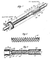
- the numeral 10 indicates generally a fuel line in the form of a thin-walled metal tube which directs diesel fuel or the like from a tank or other storage container to the fuel filter.
- a portion of the tube is wrapped or coated with a very thin layer of electrical insulating material 12, and then a ribbon of electrical resistance heater wire 14 is wound in a helix over the insulating layer.
- One end of the heater ribbon 14 is connected to an electrical terminal 16 supported on the outside of the tube by an insulating collar 18.
- the other end of the heater ribbon is connected to an electrical connector 20 supported on the tube 10 by means of an insulator sleeve 22.
- the wall of the cylindrical metal tube 10 is flattened to provide a short section 24 of tube that is substantially rectangular in cross-section. This flattened or rectangular section 24 of the tube is positioned upstream of the heater ribbon 14.
- a pair of thermistor elements 26 and 28 are mounted on the opposing surfaces of the rectangular tube section by a suitable adhesive, as described hereafter.
- Each of the thermistor elements is in the form of a thin layer of thermal resistor material 30 having a positive temperature coefficient of resistance, a material commonly referred to as a PTC thermistor.
- the thermistor is a semiconductor ceramic material manufactured by sintering a mixture of material, the main ingredient of which is barium titanate.
- the temperature response of the PTC thermistor is determined by the composition of the material and has the characteristic that it has a fairly stable resistance at lower temperatures, but at some controllable higher temperature the resistance increases sharply to a very much higher level of resistance.
- Suitable thermistor materials can be purchased commercially from a number of sources.
- suitable material for the fuel heater of the present invention is sold by T.D.K. Electronics Co., Ltd., under the designation P3-D.
- the layer of thermistor material 30 is coated on each side with a metallic film forming electrodes on the thermistor elements.
- One electrode of each thermistor is in direct contact with the flat surface of the tube and the opposite surface is electrically connected to the connector 20 through a conductor 34.
- the adhesive material bonding the thermistor elements to the tube is preferably made of an epoxy containing a high concentration of metallic or carbon particles to provide maximum thermal and electrical conductivity between the thermistor elements and the tube.
- the thermistor and heater assembly are preferably enclosed in a protective jacket 36.
- the rate at which heat is transferred from the thermistors to the fuel is critical to the proper operation of the device.
- the resistance of the two thermistor elements in parallel is less than the resistance of the heater ribbon. Since the total current through the two thermistor elements is the same as the current through the heater ribbon, the wattage of the resistance heater is larger than the wattage of the thermistor elements. If one assumes perfect heat transfer between the thermistor elements and the fuel, then there is substantially no temperature build-up in the thermistor elements when the ambient temperature of the fuel is low. This is shown by the plot of wattage versus ambient temperature as shown in FIG. 5.
- the resistance of the thermistor elements increases. And a temperature is reached, as indicated at A in FIG. 4, where the resistance of the heater ribbon and the thermistor elements is the same. At this temperature, equal wattage is, of course, produced in the heater ribbon and in the thermistor element, as shown in FIG. 5. Since the total resistance has increased, the current and hence the total wattage has decreased. With a further increase in ambient temperature, the resistance of the thermistor element rises more steeply, reducing the level of current and causing the wattage in the thermistor element to decrease along with the total wattage. Under these conditions, the thermistor element does not make a very effective switching device since the total wattage changes rather slowly over a broad temperature range.
- the temperature of the thermistor elements due to internal heating, will exceed the ambient temperature of the fuel and, as a result, the point at which the wattage is divided equally between the ribbon heater and the thermistor elements occurs at a lower ambient fuel temperature, that is, the internal heating of the thermistor causes the internal temperature of the thermistor to rise to the level at which the resistance of the thermistor is equal to the resistance of the ribbon heater at a substantially lower ambient temperature of the fuel.
- the thermistor provides a much nore effective switching action with change in ambient temperature of the fuel, and switching occurs at a lower ambient temperature for the fuel.
- the heat transfer rate is controlled to produce a sharp switching action from internal heating of the thermistor elements while still providing a stable switching point in terms of ambient temperature of the fuel over a wide range of fuel flow rates. This was accomplished by designing the thermistor elements to have maximum surface contact with the fuel line tube and using an adhesive with high thermal conductivity to secure the thermistor elements to the tube. Another feature is the addition of a mixer element 40 in the fuel line tube positioned inside the region of the thermistor elements to enhance the mixing between the fuel that comes in contact with the warmed surfaces of the tube and the fuel that flows nearer the center of the tube.
- the mixer 40 when inserted in the tube, forms a pair of helical passages which direct the fuel in a swirling or helical pattern around the inner wall of the tube as the fuel advances past the region of the thermistor elements.
- the heat transfer rate between the thermistor elements and the fuel is enhanced and maintained at a level at which a sharp switching action occurs with small changes in ambient temperature of the fuel as it enters the heater.
- a stable control over a wide range of fuel flow rates is provided by increasing fluid velocity.
- the fuel itself is used to control the heat transfer properties to produce the desired temperature versus wattage characteristic.
- the heat transfer rate between thermistor elements and the fuel is controlled so that the internal temperature rise and hence the change in resistance of the thermistor element enhances the switching action, but the heat transfer rate is not so low as to produce instability and insensitivity to ambient temperature conditions of the fuel.
- FIGS. 7-10 An alternative embodiment of the fuel heater of the present invention is shown in FIGS. 7-10.
- the fuel heater includes a tubular metal housing 50 having a closed end 52.
- An inlet opening 54 is used for admitting fuel into the heater in the mid-section of the tubular housing 50 while an outlet opening 56 directs fuel out of the heater at the closed end of the housing.
- a heater assembly is inserted into the housing from the open end.
- the top of the heater assembly includes a plug 58 at the open end of the housing, the plug supporting an electrical terminal 60 and being sealed to the housing when in place.
- the heater assembly also includes a resistance heater, indicated generally at 62, extending lengthwise of the housing from just below the input port 54 to the output port 56. The heater is directly immersed in the fuel.
- a pair of thermistor elements 64 and 66 are mounted in parallel relationship in the portion of the housing extending above the inlet port 54.
- the heater assembly 62 is constructed as shown in FIG. 10 in two zig-zag sections 70 and 72 made of flat electrical resistance material.
- the two sections are connected in series at the lower end, as indicated at 74.
- the adjoining margins of the two sections 70 and 72 are molded into a central rod or post 76 while the outer edges are respectively molded into flat ribs 78 and 80, respectively.
- the heater sections are then bent into a helical configuration, as best shown in FIG. 9, which allows the heater assembly to be inserted into the housing 50 with the rod 76 in the center and the ribs 78 and 80 against the inner wall of the housing.
- the upper end of the rod 76 has a cap 82 which is the diameter of the inside of the housing 50 and functions to center the rod 76.
- the cap includes a tapered top 84 on which the thermistor elements 64 and 66 are supported.
- the thermistor elements are inserted in slots formed on the inside of a tubular sleeve 88 which fits down on top of the cap 82.
- the sleeve has an opening which is aligned with the housing inlet 54 and allows fuel to pass through the opening into the space between the two thermistor elements above the cap 82.
- the fuel then flows upwardly between the thermistor elements into an open space 90 above the top of the thermistor elements and back down the outside of the thermistor elements through the spaces 92 and 94. These spaces communicate with openings extending through the cap 82, allowing the fuel to flow downwardly into the lower region of the housing past the heater 62 and through the outlet opening 56.
- the thermistor elements are plated on each surface to form electrodes, one electrode surface of each of the thermistor elements being connected to the electrical terminal 60 and the other electrode surface of each thermistor being connected to the upper end of the heater section 72.
- the upper end of the heater section 70 is in turn connected to the housing 50 to complete a current path from the terminal 60 to the grounded housing through the two thermistor elements in parallel and through the two heater sections 70 and 72 in series.
- FIGS. 7-10 provides direct thermal contact between the fuel and both surfaces of the two thermistor elements, as well as direct contact with the resistance heater to provide optimum heat transfer to the fuel.
- FIGS. 7-10 a mixing action to prevent layering of the heated and unheated oil in the vicinity of the thermistor surfaces can also be provided in the embodiment of FIGS. 7-10 by means of a mixing element such as shown in FIGS. 2 and 3.
- a mixing element such as shown in FIGS. 2 and 3.
- Such mixing elements can be inserted, for example, in the fluid flow paths adjacent the surfaces of the thermistor elements 64 and 66.
- An alternative mixing arrangement is shown in FIGS.
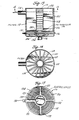
- FIGS. 13-15 Yet another embodiment of the present invention is shown in FIGS. 13-15 in which the heater element is incorporated into the filter unit.
- the filter includes an outer cylindrical wall 100 closed off at one end by an upper wall 102 and closed off at the lower end by a bottom wall 104.
- a divider wall 106 separates the interior into two chambers.
- the upper chamber includes a central perforated tube 108 which opens at its lower end into the lower chamber of the filter housing.
- the annular space between the outer wall 100 and the tube 108 contains a folded filter element 110, such as a pleated paper filter.
- a thermistor controlled heating element assembly is positioned in the lower chamber between the inlet tube 112 and the perforated tube 108.
- the heater assembly as shown in FIG. 15, comprises a molded plastic frame 116 having an outer rim section 118, an inner rim section or hub 120 and four radial spokes 122 joining the rim 118 to the hub 120.
- a positive temperature coefficient thermistor element in the form of a disc is mounted inside the hub 120.
- a resistance wire heating element 126 is positioned in the annular space between the outer rim 118 and the hub 120, the heater element being embedded in and supported by the spokes 122.
- One end of the heater element is connected to an outer terminal 130 while the other end of the heater element is connected to the thermistor element 124 by a terminal 132.
- a heat sink and electrical terminal 134 is attached to the opposite side of the thermistor 132 and is positioned directly in the intake flow path of the filter opposite the inlet tube 112.
- the terminal 134 is grounded in any suitable manner to the wall of the filter housing while the terminal 132 is brought out through the side wall of the housing for connection to a battery or other power source.
- the cold fuel enters the inlet to the filter and into thermal contact with the thermistor element through the heat sink 134, cools the thermistor, thus reducing the resistance of the thermistor element and increasing the current flowing through the resistance heater.
- the rate of heat transfer from the thermistor element to the fuel is designed to provide the effect described above in connection with the curve shown in FIGS. 4-6.
- the fuel is essential to the operation of the heater switching operation.
- the fuel forms an imperfect heat sink which controls the temperature change in the thermistors to produce an abrupt switching action from full heater power to a much reduced heater power. This insures that there is no undue current drain at higher ambient temperature conditions but there is maximum power when the ambient temperature falls below a critical level.
Landscapes
- Engineering & Computer Science (AREA)
- Chemical & Material Sciences (AREA)
- Combustion & Propulsion (AREA)
- Mechanical Engineering (AREA)
- General Engineering & Computer Science (AREA)
- Ceramic Engineering (AREA)
- Resistance Heating (AREA)
- Control Of Combustion (AREA)
- Measurement Of Levels Of Liquids Or Fluent Solid Materials (AREA)
Applications Claiming Priority (2)
| Application Number | Priority Date | Filing Date | Title |
|---|---|---|---|
| US06/399,337 US4477715A (en) | 1982-07-19 | 1982-07-19 | PTC thermistor controlled electric diesel fuel heater |
| US399337 | 1982-07-19 |
Publications (2)
| Publication Number | Publication Date |
|---|---|
| EP0101560A2 true EP0101560A2 (de) | 1984-02-29 |
| EP0101560A3 EP0101560A3 (de) | 1985-01-09 |
Family
ID=23579158
Family Applications (1)
| Application Number | Title | Priority Date | Filing Date |
|---|---|---|---|
| EP83106976A Withdrawn EP0101560A3 (de) | 1982-07-19 | 1983-07-15 | Thermistorgesteuerter Brennstoffvorwärmer |
Country Status (2)
| Country | Link |
|---|---|
| US (1) | US4477715A (de) |
| EP (1) | EP0101560A3 (de) |
Cited By (6)
| Publication number | Priority date | Publication date | Assignee | Title |
|---|---|---|---|---|
| EP0135704A1 (de) * | 1983-08-03 | 1985-04-03 | Grote & Hartmann GmbH & Co. KG | Widerstandsheizelement |
| EP0119807A3 (de) * | 1983-03-11 | 1985-05-15 | RAYCHEM CORPORATION (a Delaware corporation) | Aufheizen von Flüssigkeiten |
| US4571481A (en) * | 1983-03-11 | 1986-02-18 | Raychem Corporation | Method and apparatus for electrically heating diesel fuel |
| WO1987000887A1 (fr) * | 1985-08-03 | 1987-02-12 | Georg Feder | Dispositif de prechauffage de carburant diesel |
| EP0284120A1 (de) * | 1987-02-20 | 1988-09-28 | Texas Instruments Holland B.V. | Vorrichtung zum Vorwärmen von Brennstoff, insbesondere von Dieselbrennstoff |
| EP0793399A3 (de) * | 1996-02-29 | 1998-04-29 | BERU Ruprecht GmbH & Co. KG | Selbstregelndes Heizelement |
Families Citing this family (37)
| Publication number | Priority date | Publication date | Assignee | Title |
|---|---|---|---|---|
| JPS59190462A (ja) * | 1983-04-12 | 1984-10-29 | Nippon Denso Co Ltd | 燃料加熱型燃料フイルタ装置 |
| US4547287A (en) * | 1984-03-07 | 1985-10-15 | Champion Laboratories, Inc. | Thermostatically controlled pack hold-down assembly |
| US4579653A (en) * | 1984-08-17 | 1986-04-01 | Davco Manufacturing Corporation | Side-by-side fuel processor apparatus |
| US4650576A (en) * | 1984-12-28 | 1987-03-17 | Raychem Corporation | Apparatus for regenerative heating of diesel fuel |
| US4598686A (en) * | 1985-03-28 | 1986-07-08 | Casco Products Inc. | Fuel vapor recovery system for automotive vehicles |
| US4748960A (en) * | 1986-04-14 | 1988-06-07 | Gilbert Wolf | Fuel system |
| US4790285A (en) * | 1986-05-15 | 1988-12-13 | Gilbert Wolf | Fuel system |
| US4721846A (en) * | 1986-07-02 | 1988-01-26 | Casco Products Corporation | Canister heater with PTC wafer |
| US4732671A (en) * | 1986-08-04 | 1988-03-22 | Allied Corporation | Diesel fuel filter/water separator |
| US4818842A (en) * | 1986-08-22 | 1989-04-04 | Walty Robert J | Diesel fuel heater |
| US4717401A (en) * | 1986-09-24 | 1988-01-05 | Casco Products Corporation | Fuel vapor recovery system |
| USD324052S (en) | 1989-01-23 | 1992-02-18 | Dennis Dean | Carburetor enhancement pump |
| DE3918663A1 (de) * | 1989-06-08 | 1990-12-13 | Eberspaecher J | Anordnung zur brennstoffvorwaermung fuer einen ultraschallzerstaeuber fuer heizgeraete |
| US5050569A (en) * | 1989-12-22 | 1991-09-24 | Texas Instruments Incorporated | Fuel injection system for an internal combustion engine and fuel heating device therefor |
| FR2690112B1 (fr) * | 1992-04-21 | 1995-06-23 | Valeo Thermique Habitacle | Dispositif de chauffage-ventilation de l'habitacle d'un vehicule automobile propulse par un moteur a faibles rejets thermiques. |
| US5231968A (en) * | 1992-07-27 | 1993-08-03 | Donald Siefkes | Foamed metal heat device |
| US5533486A (en) * | 1993-12-23 | 1996-07-09 | Freightliner Corporation | Fuel system for heating and cooling fuel |
| US5981910A (en) * | 1997-05-06 | 1999-11-09 | Williams; Wayne | Heated cover for a fuel filter |
| US7158718B2 (en) * | 2000-06-14 | 2007-01-02 | Watlow Electric Manufacturing Company | Electric heating device |
| CN1144699C (zh) * | 2001-03-20 | 2004-04-07 | 邱文星 | 能源媒体 |
| US6795646B1 (en) | 2003-10-21 | 2004-09-21 | Fleetguard, Inc. | Fuel heater with cam removal feature |
| US7020389B2 (en) * | 2003-10-21 | 2006-03-28 | Fleetguard, Inc. | Fuel heater with cam removal feature |
| US20050188963A1 (en) * | 2004-03-01 | 2005-09-01 | Gofar Laboratories | System, vaporizing fuel in vehicle |
| RU2270355C1 (ru) * | 2004-05-17 | 2006-02-20 | Федеральное государственное образовательное учреждение высшего профессионального образования Ульяновская государственная сельскохозяйственная академия | Устройство для обработки и очистки топлива двигателей внутреннего сгорания |
| DE102005037201A1 (de) * | 2005-08-06 | 2007-02-22 | Eichenauer Heizelemente Gmbh & Co. Kg | Heizsystem |
| ES2354964T3 (es) * | 2006-06-28 | 2011-03-21 | EBERSPÄCHER CATEM GMBH & CO. KG | Dispositivo de calefacción eléctrico. |
| DE102006047042A1 (de) * | 2006-10-02 | 2008-04-03 | Emitec Gesellschaft Für Emissionstechnologie Mbh | Vorrichtung und Verfahren zum Verdampfen eines Reaktionsmittels |
| DE102007010503B4 (de) * | 2007-03-05 | 2017-12-07 | Robert Bosch Gmbh | Bauteil für einen Flüssigkeitsfilter und Flüssigkeitsfilter |
| DE102008012972A1 (de) * | 2008-03-06 | 2009-09-10 | Emitec Gesellschaft Für Emissionstechnologie Mbh | Verdampfungseinheit zur Erzeugung eines mindestens einen Reduktionsmittelvorläufer und/oder ein Reduktionsmittel umfassenden Gases |
| JP2011516770A (ja) * | 2008-02-29 | 2011-05-26 | エミテック ゲゼルシヤフト フユア エミツシオンス テクノロギー ミツト ベシユレンクテル ハフツング | 少なくとも1つの還元剤前駆体および/または還元剤を含むガスを生成するための蒸発装置 |
| DE102009009790B3 (de) * | 2009-02-20 | 2010-06-17 | Schauenburg Hose Technology Gmbh | Beheizbarer Schlauch |
| DE102009025135A1 (de) * | 2009-06-17 | 2010-12-23 | Emitec Gesellschaft Für Emissionstechnologie Mbh | Vorrichtung zur Verdampfung einer Harnstoff-Wasser-Lösung |
| JP6594758B2 (ja) * | 2015-12-10 | 2019-10-23 | 株式会社マーレ フィルターシステムズ | キャニスタ用ヒータ |
| CA3028988A1 (en) * | 2016-03-01 | 2017-09-08 | CT Energy Holdings, LLC | Fuel heating apparatus and methods |
| US11237067B2 (en) * | 2019-08-20 | 2022-02-01 | Kidde Technologies, Inc. | Uncertainty diagnosis for temperature detection systems |
| US20210146755A1 (en) * | 2019-11-14 | 2021-05-20 | Lexmark International, Inc. | Cabin heater for vehicle |
| US11092358B1 (en) * | 2020-02-14 | 2021-08-17 | Eberspächer Catem Gmbh & Co. Kg | Electrical heating device |
Family Cites Families (11)
| Publication number | Priority date | Publication date | Assignee | Title |
|---|---|---|---|---|
| US3235084A (en) * | 1962-01-30 | 1966-02-15 | Stewart Warner Corp | Fuel filter with heating unit |
| US3400252A (en) * | 1965-10-20 | 1968-09-03 | Matsushita Electric Industrial Co Ltd | Electrical heating device |
| US3375774A (en) * | 1967-01-05 | 1968-04-02 | Matsushita Electric Industrial Co Ltd | Fully automatic electric coffee pot |
| US3476293A (en) * | 1967-08-29 | 1969-11-04 | Texas Instruments Inc | Aerosol heater with improved control means |
| DE2132519A1 (de) * | 1971-06-30 | 1973-01-11 | Koerting Oel Gasfeuerung | Einrichtung zum erwaermen eines fliessenden heizoels |
| DE2316054A1 (de) * | 1973-03-30 | 1974-10-10 | Siemens Ag | Kaltleiterheizung fuer kraftstoff |
| EP0017057B1 (de) * | 1979-03-27 | 1982-03-10 | Danfoss A/S | Vorrichtung zum Vorwärmen von Heizöl |
| DE2919763C2 (de) * | 1979-05-16 | 1983-07-07 | Danfoss A/S, 6430 Nordborg | Zerstäubungsbrenner für Ölfeuerungsanlagen |
| EP0045507A3 (de) * | 1980-08-04 | 1982-08-04 | Technar Incorporated | Brennstoffheizgerät für Diesel-Motoren |
| US4387691A (en) * | 1980-11-07 | 1983-06-14 | Texas Instruments Incorporated | Diesel fuel filter system |
| US4372279A (en) * | 1980-11-24 | 1983-02-08 | Paccar Inc. | Heated fuel line |
-
1982
- 1982-07-19 US US06/399,337 patent/US4477715A/en not_active Expired - Fee Related
-
1983
- 1983-07-15 EP EP83106976A patent/EP0101560A3/de not_active Withdrawn
Cited By (6)
| Publication number | Priority date | Publication date | Assignee | Title |
|---|---|---|---|---|
| EP0119807A3 (de) * | 1983-03-11 | 1985-05-15 | RAYCHEM CORPORATION (a Delaware corporation) | Aufheizen von Flüssigkeiten |
| US4571481A (en) * | 1983-03-11 | 1986-02-18 | Raychem Corporation | Method and apparatus for electrically heating diesel fuel |
| EP0135704A1 (de) * | 1983-08-03 | 1985-04-03 | Grote & Hartmann GmbH & Co. KG | Widerstandsheizelement |
| WO1987000887A1 (fr) * | 1985-08-03 | 1987-02-12 | Georg Feder | Dispositif de prechauffage de carburant diesel |
| EP0284120A1 (de) * | 1987-02-20 | 1988-09-28 | Texas Instruments Holland B.V. | Vorrichtung zum Vorwärmen von Brennstoff, insbesondere von Dieselbrennstoff |
| EP0793399A3 (de) * | 1996-02-29 | 1998-04-29 | BERU Ruprecht GmbH & Co. KG | Selbstregelndes Heizelement |
Also Published As
| Publication number | Publication date |
|---|---|
| US4477715A (en) | 1984-10-16 |
| EP0101560A3 (de) | 1985-01-09 |
Similar Documents
| Publication | Publication Date | Title |
|---|---|---|
| US4477715A (en) | PTC thermistor controlled electric diesel fuel heater | |
| US8641896B2 (en) | Filter device, in particular fluid filter, with a heater | |
| AU646498B2 (en) | Switch controlled, zone-type heating cable and method | |
| EP0051936B1 (de) | Filteranordnung für Dieselkraftstoff | |
| US4585924A (en) | Self-contained electric diesel engine fuel filter assembly heater | |
| US4091265A (en) | Fuel filter heating assembly | |
| US5547572A (en) | Fuel Filter | |
| US3375774A (en) | Fully automatic electric coffee pot | |
| US4131657A (en) | Electric automotive choke | |
| US3699937A (en) | Solid state controlled automatic choke | |
| JP4503812B2 (ja) | 燃料フィルタ | |
| US4259937A (en) | Fuel treatment device | |
| US3400252A (en) | Electrical heating device | |
| US20110309068A1 (en) | Heating element for a hot air device | |
| US4473054A (en) | Diesel fuel filter system | |
| JPS59224463A (ja) | デイ−ゼルエンジン用燃料フイルタ−装置 | |
| US5965049A (en) | Self-regulating electric heating element for heaters shaped as cartridges or test tubes | |
| US7086607B2 (en) | Electrical dispenser for deodorant or insecticide | |
| US7172133B2 (en) | Heatable dilation element | |
| US4096837A (en) | Automatic choking device of electric heating type | |
| US5004893A (en) | High-speed, high temperature resistance heater and method of making same | |
| GB1568503A (en) | Filter for liquids | |
| US4730103A (en) | Compact PTC resistance heater | |
| EP0657698B1 (de) | Glühkerze mit Selbsregelung des Stromes | |
| JP3219110B2 (ja) | Ptc発熱体 |
Legal Events
| Date | Code | Title | Description |
|---|---|---|---|
| PUAI | Public reference made under article 153(3) epc to a published international application that has entered the european phase |
Free format text: ORIGINAL CODE: 0009012 |
|
| AK | Designated contracting states |
Designated state(s): DE FR GB IT |
|
| PUAL | Search report despatched |
Free format text: ORIGINAL CODE: 0009013 |
|
| AK | Designated contracting states |
Designated state(s): DE FR GB IT |
|
| 17P | Request for examination filed |
Effective date: 19850705 |
|
| 17Q | First examination report despatched |
Effective date: 19860224 |
|
| R17C | First examination report despatched (corrected) |
Effective date: 19870223 |
|
| STAA | Information on the status of an ep patent application or granted ep patent |
Free format text: STATUS: THE APPLICATION IS DEEMED TO BE WITHDRAWN |
|
| 18D | Application deemed to be withdrawn |
Effective date: 19910607 |
|
| APAF | Appeal reference modified |
Free format text: ORIGINAL CODE: EPIDOSCREFNE |
|
| RIN1 | Information on inventor provided before grant (corrected) |
Inventor name: BELL, LON EDWARD Inventor name: GRUBER, WILLIAM PAUL |