EP0101580B1 - Indicateur capacitif de niveau de matière - Google Patents
Indicateur capacitif de niveau de matière Download PDFInfo
- Publication number
- EP0101580B1 EP0101580B1 EP83107519A EP83107519A EP0101580B1 EP 0101580 B1 EP0101580 B1 EP 0101580B1 EP 83107519 A EP83107519 A EP 83107519A EP 83107519 A EP83107519 A EP 83107519A EP 0101580 B1 EP0101580 B1 EP 0101580B1
- Authority
- EP
- European Patent Office
- Prior art keywords
- capacitance
- set forth
- responsive
- system set
- counter
- Prior art date
- Legal status (The legal status is an assumption and is not a legal conclusion. Google has not performed a legal analysis and makes no representation as to the accuracy of the status listed.)
- Expired
Links
Images

Classifications
-
- G—PHYSICS
- G01—MEASURING; TESTING
- G01F—MEASURING VOLUME, VOLUME FLOW, MASS FLOW OR LIQUID LEVEL; METERING BY VOLUME
- G01F23/00—Indicating or measuring liquid level or level of fluent solid material, e.g. indicating in terms of volume or indicating by means of an alarm
- G01F23/22—Indicating or measuring liquid level or level of fluent solid material, e.g. indicating in terms of volume or indicating by means of an alarm by measuring physical variables, other than linear dimensions, pressure or weight, dependent on the level to be measured, e.g. by difference of heat transfer of steam or water
- G01F23/26—Indicating or measuring liquid level or level of fluent solid material, e.g. indicating in terms of volume or indicating by means of an alarm by measuring physical variables, other than linear dimensions, pressure or weight, dependent on the level to be measured, e.g. by difference of heat transfer of steam or water by measuring variations of capacity or inductance of capacitors or inductors arising from the presence of liquid or fluent solid material in the electric or electromagnetic fields
- G01F23/263—Indicating or measuring liquid level or level of fluent solid material, e.g. indicating in terms of volume or indicating by means of an alarm by measuring physical variables, other than linear dimensions, pressure or weight, dependent on the level to be measured, e.g. by difference of heat transfer of steam or water by measuring variations of capacity or inductance of capacitors or inductors arising from the presence of liquid or fluent solid material in the electric or electromagnetic fields by measuring variations in capacitance of capacitors
- G01F23/266—Indicating or measuring liquid level or level of fluent solid material, e.g. indicating in terms of volume or indicating by means of an alarm by measuring physical variables, other than linear dimensions, pressure or weight, dependent on the level to be measured, e.g. by difference of heat transfer of steam or water by measuring variations of capacity or inductance of capacitors or inductors arising from the presence of liquid or fluent solid material in the electric or electromagnetic fields by measuring variations in capacitance of capacitors measuring circuits therefor
-
- G—PHYSICS
- G01—MEASURING; TESTING
- G01F—MEASURING VOLUME, VOLUME FLOW, MASS FLOW OR LIQUID LEVEL; METERING BY VOLUME
- G01F23/00—Indicating or measuring liquid level or level of fluent solid material, e.g. indicating in terms of volume or indicating by means of an alarm
- G01F23/22—Indicating or measuring liquid level or level of fluent solid material, e.g. indicating in terms of volume or indicating by means of an alarm by measuring physical variables, other than linear dimensions, pressure or weight, dependent on the level to be measured, e.g. by difference of heat transfer of steam or water
- G01F23/26—Indicating or measuring liquid level or level of fluent solid material, e.g. indicating in terms of volume or indicating by means of an alarm by measuring physical variables, other than linear dimensions, pressure or weight, dependent on the level to be measured, e.g. by difference of heat transfer of steam or water by measuring variations of capacity or inductance of capacitors or inductors arising from the presence of liquid or fluent solid material in the electric or electromagnetic fields
- G01F23/263—Indicating or measuring liquid level or level of fluent solid material, e.g. indicating in terms of volume or indicating by means of an alarm by measuring physical variables, other than linear dimensions, pressure or weight, dependent on the level to be measured, e.g. by difference of heat transfer of steam or water by measuring variations of capacity or inductance of capacitors or inductors arising from the presence of liquid or fluent solid material in the electric or electromagnetic fields by measuring variations in capacitance of capacitors
- G01F23/268—Indicating or measuring liquid level or level of fluent solid material, e.g. indicating in terms of volume or indicating by means of an alarm by measuring physical variables, other than linear dimensions, pressure or weight, dependent on the level to be measured, e.g. by difference of heat transfer of steam or water by measuring variations of capacity or inductance of capacitors or inductors arising from the presence of liquid or fluent solid material in the electric or electromagnetic fields by measuring variations in capacitance of capacitors mounting arrangements of probes
Definitions
- the present invention is directed to a system for indicating the level of material in a vessel
- a resonant circuit including a capacitance probe adapted to be disposed in the vessel so as to be responsive to variations in capacitance as a function of material level in said vessel, oscillator means coupled to said resonant circuit including said capacitance probe, phase detection means responsive to variations in phase angle at said oscillator means as a function of probe capacitance, means for identifying a reference capacitance indicative of a predetermined level of material in said vessel, and means responsive to said phase detection means and to the identifying means for indicating material level in said vessel as a function of a difference between said probe capacitance and said reference capacitance.
- US-A-3391547 illustrates a system of this type wherein the probe capacitance is connected in a capacitance bridge.
- GB-A-2025623 discloses a system of similar type wherein amplitude rather than phase variation is employed to measure material level.
- EP-A-0044434 discloses a similar system for indicating the level of material in a vessel, comprising a capacitance probe adapted to be disposed in the vessel so as to be responsive to variations in capacitance as a function of material level in said vessel, oscillator means coupled to said capacitance probe, calibration means for identifying a reference capacitance (cf. the capacitance between the sensing element and the conductive member in the absence of the material) indicative of a predetermined level of material in said vessel, and means responsive to said calibration means for indicating material level in said vessel as a function of the difference between capacitance at said probe and said reference capacitance.
- a reference capacitance cf. the capacitance between the sensing element and the conductive member in the absence of the material
- the present invention provides a material level indicating system which may be readily calibrated in the field by relatively unskilled personnel for a variety of applications and environments. Furthermore, such system includes facility for rapid and automatic recalibration in the field by an unskilled operator.
- the material level indicating system of the present invention has reduced sensitivity to the effects of material coating on the capacitance probe and/or to the effects of conductivity or variation in conductivity of the sensed material.
- Fig. 1 illustrates a presently preferred embodiment of the material level indicating system of the invention as comprising an rf oscillator 10 which provides a periodic signal at a first output to a phase shift (90°) amplifier 12.
- the sinusoidal output of amplifier 12 is connected to an adjustable parallel LC resonant circuit 14.
- Resonant circuit 14 is connected to the probe conductor 18 of a probe assembly 20 (Figs. 1 and 6) mounted in the side wall of a storage vessel 22.
- the output of amplifier 12 is also connected through a unity gain amplifier 24 having low output impedance to the guard shield 26 of probe assembly 20.
- the wall of vessel 22, which may be a storage bin for solid materials or a liquid storage tank, is connected to ground.
- Guard shield 26 which is energized by amplifier 24 at substantially the same voltage and phase as probe conductor 18, functions to prevent leakage of probe energy through material coated onto the probe surface, and thus to direct probe radiation outwardly into the vessel volume so as to be more closely responsive to the level of material stored therein.
- phase detector 32 receives a square wave second input from a second output of oscillator 10 180° out of phase with the oscillator output directed to amplifier 12.
- a first output of phase detector 32 which is a d.c. signal at a level proportional to the phase relationship between the respective inputs, and thus responsive to variations in phase angle of the oscillator probe drive output due to changes in probe capacitance, is fed to an automatic calibration circuit 34.
- a second output of phase detector 32 which is also a d.c. signal indicative of input phase relationship, is directed to one input of a threshold detector 36.
- phase detector 32 The outputs of phase detector 32 are identical but effectively isolated from each other for reasons that will become apparent.
- Automatic calibration circuit (identifying means) 34 provides a control input to adjustable LC resonant circuit 14 which receives a second input for adjustment purposes from oscillator 10.
- Calibration circuit 34 also provides a reference input to threshold detector 36.
- the output of threshold detector 36 is fed through material level indicating circuitry 38 to external circuitry for controlling and/or indicating vessel material level as desired.
- automatic calibration circuitry 34 functions to adjust the resonance characteristics . of resonant circuit 14 during a calibration mode of operation initiated by an operator push-button 40 connected thereto so as to establish, in effect, a reference capacitance level indicative of a preselected material condition in vessel 22 which exists during the automatic calibration mode.
- the level of material in vessel 22 is first raised (by means not shown) to the level of probe assembly 20 and then lowered so as to be spaced from the probe assembly. If material 28 is of a type which coats the probe assembly, such coating will remain on the probe and be taken into consideration during the ensuing calibration operation. With the material level lowered, an operator may push button 40 to initiate the automatic calibration mode of operation.
- the resonance characteristics of circuit 14 are then automatically varied or adjusted by calibration circuit 34 until the output of phase detector 32 indicates that the return signal from the parallel combination of resonant circuit 14 and capacitance probe 20 bears a preselected phase relationship to the oscillator reference input to phase detector 32, which phase relationship thus corresponds to an effective reference capacitance level at calibration circuit 34 indicative of a low material level.
- phase detector 32 is compared in threshold detector 36 to a reference input from calibration circuit 34 indicative of the reference capcitance level, and threshold detector 36 provides an output to material level indicating circuitry 38 when the sensed capacitance exceeds the reference capacitance level by a predetermined amount which is selected as a function of material dielectric constant. If probe 20 is placed in the upper portion of vessel 22 as shown in Fig. 1, such proximity would normally indicate a full tank condition.
- probe 20 is disposed in the lower portion of tank 22, material would normally be in proximity to the probe assembly, and indeed would normally cover the probe assembly, so that absence of such proximity would indicate an empty tank condition.
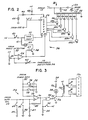
- Fig. 2 illustrates a presently preferred embodiment of automatic calibration circuitry 34 and adjustable LC resonant circuit 14.
- Resonant circuit 14 includes a fixed capacitor 42 and an inductance 44 connected in parallel with probe conductor 18 across the output of amplifier 12, i.e. between the amplifier output and ground.
- Inductance 44 comprises a plurality of inductor coils or windings having a number of connection taps at electrically spaced positions among the inductor coil turns.
- a plurality of fixed capacitors 46a-46f are each electrically connected in series with a respective controlled electronic switch 48a-48f between a corresponding connection tap on inductance coil 44 and electrical ground. Switches 48a-48f may comprise any suitable electronic switches and are normally open in the absence of a control input.
- a digital counter 50 receives a count input from oscillator 10 and provides a plurality of parallel digital outputs each indicative of a corresponding bit of the count stored in counter 50.
- Each data bit output of counter 50 is connected to control a corresponding electronic switch 48a-48f for selectively connecting or disconnecting the corresponding capacitor 46a-46f in resonant circuit 14 as a function of the state of the counter output bit.
- the capacitance values of capacitors 46a-46f and the number of coil turns separating the connection taps of inductance 44 are selected such that the effective capacitance added to the parallel LC resonant circuit 14 by each capacitor 46a-46f corresponds to the numerical significance of the corresponding counter output. That is, assuming that counter 50 is a binary counter with outputs connected to switches 48a-48f in reverse order of significance, the values of capacitors 46e, 46f and the number of turns at inductance 44 therebetween are selected such that the effective capacitance connected in parallel with fixed capacitor 42 and probe 20 is twice as much when switch 48e only is closed as when switch 48f only is closed.
- the effective capacitance added by switch 48a and capacitor 46a is thirty- two times the effective value of capacitor 46f and switch 48f.
- inductance 44 functions as an autotransformer so as to establish the effective capacitance of each capacitor 46 as a function of the corresponding connection point among the inductance coils.
- the number of inductance connection taps may be less than the number of capacitors 46a-46f, with two or more capacitors connected to one tap.
- the values of capacitors connected to a common tap should differ by multiples of approximately two in correspondence with the significance of the control bits from counter 50.
- Automatic calibration circuit 34 illustrated in Fig. 2 includes a one shot 52 which receives an input from operator push-button 40 and provides an output to the reset input of counter 50 in resonant circuit 14 to initiate the automatic calibration mode of operation.
- a differential comparator (comparison means) 54 has an inverting input connected to the output of phase detector 32 and a non-inverting input connected to the wiper of a variable resistor 56. Resistor 56 is connected across a source d.c. potential. The output of comparator 54 is connected to the enabling input of counter 50 in resonant circuit 14.
- comparator 54 is also connected through a resistor 57 to the base of an NPN transistor 58 which functions as an electronic switch having collector and emitter electrodes connected in series with an LED 60, a resistor 61 and operator switch 40 across a source of d.c. potential.
- the non-inverting input of comparator 54 is also connected through an adjustable resistor 62 to threshold detector 36 (Figs. 1 and 3).
- Resistor 56 is preferably factory set to correspond with a resonance condition at circuit 14 for a low-level or "empty-vessel" nominal capacitance with no coating on probe 20 and all capacitors 46a-46f in circuit.
- the empty-tank capacitance at probe 20 may be 15 picofarads, for example.
- phase detector 32 When the output of phase detector 32 reaches this reference capacitance level input to comparator 54, which is preferably at substantially the resonance condition of the LC resonant circuit, the output of differential amplifier 54 switches to a high or one logic stage. Further operation of counter 50 is inhibited and LED 60 is illuminated through transistor 58 so as to indicate to an operator that the calibration operation has been completed. The operator may then release switch 40.
- the resonance circuit is designed to be at resonance with all capacitors 46a-46f in circuit and the probe uncoated.
- the automatic calibration operation functions to delete one or more capacitors 46a ⁇ 46f from the parallel resonance circuit to compensate for the coating on the probe, cable capacitance, tank geometry, parasitic capacitance, and variations in probe insertion length and circuit operating characteristics.
- adjustable LC resonant circuit 14 receives input power from a suitable power supply (not shown) energized by a utility power source.
- a suitable power supply not shown
- adjustable LC resonant circuit 14 further includes a battery 64 connected by the blocking diodes 66, 68 in parallel with the power supply d.c. voltage to the power input terminal of counter 50 so as to maintain the calibration count therein in the event of power failure.
- threshold detector 36 includes a differential comparator (comparison means) 70 having an inverting input connected to the second output of phase detector 32 (Fig. 1) and a non-inverting input connected through adjustable resistor 62 (Fig. 2) to reference- indicating adjustable resistor 56.
- a pair of capacitors 72, 74 are connected through corresponding jumpers 76, 78 between the inverting input of comparator 70 and ground.
- a third capacitor 75 is also connected between the inverting input of comparator 70 and ground.
- Capacitors 72, 74, 75 and jumpers 76, 78 provide a factory-selectable or field-selectable adjustable delay in operation of threshold detector 36 so that a transient condition will not result in an erroneous indication of change of material level.
- phase detector outputs are isolated as previously described so that delay capacitors 72, 74, 75 will not affect operation in the calibration mode.
- a pair of resistors 80, 82 are connected by corresponding jumpers 84, 86 between the non-inverting input of comparator 70 and ground.
- a third resistor 87 is directly connected between the non-inverting comparator input and ground.
- Resistors 80, 82, 87 and jumpers 84, 86 cooperate with resistor 62 (Fig. 2) to provide factory or field selectable adjustment of the capacitance differential sensed by threshold detector 36 between the reference set by resistor 56 (Fig. 2) and the material-proximate material level which probe 20 is intended to indicate.
- the difference between the capacitance at probe 20 corresponding to the reference level of resistor 56 with the material at low level and a full-tank capacitance is the. capacitance increase caused by rise in material level into proximity with the capacitance probe.
- Resistors 80, 82, 87 and jumpers 80, 84 effectively select the capacitance differential to be sensed between low and high material level conditions.
- jumpers 84, 86 are removed and a threshold level corresponding to a capacitance differential of four picofarads, for example, is established by resistors 62, 87.
- jumper 84 may be added so that resistors 80, 87 in parallel establish a higher capacitance differential of eight picofarads, for example, corresponding to the same high material level. A still higher capacitance differential may be established with jumper 84 removed and jumper 86 intact.
- both jumpers 84, 86 may remain intact, so that resistors 80, 82, 87 in parallel establish a maximum capacitance differential of twenty picofarads, for example.
- differential comparator 70 switches from a low or logical zero level to a high or logical one level, thereby indicating proximity of material to the probe assembly.
- a resistor 88 is connected between the output of comparator 70 and the non-inverting input thereof to establish a hysteresis in comparator operation and thereby avoid intermittent switching of comparator output at a borderline material level condition.
- the output of differential comparator 70 is also connected in material level indicating circuitry 38 to one input of an exclusive-or gate 90.
- the second input of gate 90 is connected through a jumper 92 to the positive voltage supply and through a resistor 94 to ground.
- the output of gate 90 is connected through a resistor 95 to the base of an NPN transistor 96 which functions as an electronic switch to illuminate an LED 98 through a resistor 99 and to energize a relay coil 100 when the output of gate 90 assumes a high or logical one condition.
- the contacts 102 associated with relay coil 100 are connected to corresponding terminals of a terminal block 104 for connection to external circuitry as previously described.
- Jumper 92 and resistor 94 cooperate with gate 90 for selecting either low level or high level fail safe operation of material level indicating circuitry 38. That is, jumper 92 and resistor 94 cooperate with gate 90 to de-energize relay coil 100 at either a high level condition (material proximate to probe 20) or a low level condition (material spaced from probe 20). In this way, the selected high level or low level condition will also be indicated to the external circuitry independently of actual material level in the event that relay coil 100 is de-energized by a power failure or the like. As previously indicated, the output of comparator 70 assumes a high or logical one voltage level when material 28 is in proximity to probe 20 (Fig. 1).
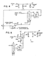
- Figs. 4 and 5 illustrate respective modifications to the preferred embodiment of the invention hereinabove described. Only the differences between the respective modifications and the preferred embodiment are illustrated in Figs. 4 and 5 and described hereinafter.
- the adjustable LC resonant circuit of the preferred embodiment is replaced by a non-adjustable resonant circuit comprising a fixed capacitor 104 and a fixed inductor 102 connected in parallel with each other and with probe 20.
- capacitor 104 and inductor 102 are selected so as to exhibit resonance at the frequency of oscillator 10 in combination with an empty-tank capacitance at probe 20 (uncoated), such as fifteen picofarads for example.
- the bit-parallel data output of counter 50 is fed to a digital-to-analog converter 106 which provides an analog output voltage to reference resistor 56 in place of the fixed power supply voltage in the preferred embodiment of the invention previously described so as to vary the reference input voltage to comparator 54 as a function of the count in counter 50.
- Differential comparator 54 receives inputs from phase detector 32 and reference resistor 56, and terminates operation of the automatic calibration mode by removing the enabling input from counter 50 when the reference voltage supplied by resistor 56 to the inverting input of comparator 54 is equal to the output from phase detector 32 corresponding to the coated probe empty vessel calibration condition at probe 20.
- Fig. 5 illustrates a modified adjustable resonant circuit 107 which includes a source 108 of direct current controlled by the output of d/a converter 106 and connected to coil 102 for varying the effective inductance thereof as a function of the count in counter 50.
- Current source 108 includes a PNP transistor 110 having an emitter connected through a capacitor 112 to the output of amplifier 12 (Fig. 1) and through a resistor 114to a positive d.c. voltage source.
- the base of transistor 110 is connected to the output of d/a converter 106 and through a resistor 116 to the voltage source.
- the collector of transistor 110 is connected to the parallel resonant circuit comprising inductor 102, capacitor 104 and probe 20.
- the direct current fed by transistor 110 to coil 102 decreases correspondingly, and thereby decreases the effective a.c. inductance of coil 102 to compensate for increased probe capacitance caused by material coating.
- the effective inductance is decreased to a point where the parallel combination of capacitance 104, inductor 102 and coated probe 20 are substantially at resonance, operation of counter 50 is terminated by differential comparator 54 (Fig. 2) in the manner previously described.
- Resistor 116 may be variable for factory adjustment of current source gain.
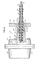
- Fig. 6 illustrates a presently preferred embodiment of probe assembly 20 in accordance with the invention as comprising a closed metal housing 120 which has a base 121 and a cover 123 separable therefrom.
- the system electronics hereinabove described are preferably disposed within housing 120 and connected through the opening 122 in base 121 for receiving power from a source remote from the probe assembly, for receiving a calibration signal from switch 40 (Figs. 1 and 2) which may also be located remotely of the probe assembly, and for connection of terminal block 104 (Fig. 3) to external circuitry.
- a hollow nipple 124 projects from housing base 121.
- the housing-remote end of nipple 124 is internally threaded up to an inwardly tapering shoulder 125 coaxial with nipple 124.
- a hollow externally threaded adapter 130 is received within nipple 124.
- the interior of adapter 130 is formed at a first diameter 128 which blends into a second smaller diameter 129 by means of a tapering shoulder 131.
- Diameters 128, 129 and shoulder 131 are coaxial in assembly with nipple 124.
- the housing-remote end of adapter 130 is adapted to be threadably received into an internally threaded gland 140 mounted on the side or top wall of a material storage vessel 142 so that probe rod 20 and guard shield 26 project internally of the vessel as shown in Fig. 1.
- a probe subassembly 133 comprising the probe measurement element 18, the guard shield 26 and a one-piece unitarily formed body of insulating material 126 formed therearound and therebetween.
- measurement element 18 comprises a solid rod of conductive non-corrosive metallic material such as stainless steel having an internally threaded opening at one end adapted for connection as at 134 within housing 120 to adjustable resonant circuit 14 (Fig. 1).
- Guard shield 26 comprises a hollow cylindrical tube of conductive metallic material such as stainless steel co-axially surrounding and radially spaced from probe rod 18. Guard shield 26 in the preferred embodiment of the drawing is substantially shorter in the axial dimension than is probe rod 18 and is spaced intermediate the rod ends.
- the guard shield extends from a position located radially inwardly of the housing-remote end of adapter 130 to a point spaced from the housing-remote end of probe rod 18.
- An insulated conductor 132 is soldered or otherwise electrically connected to guard shield 26 and extends along rod 18 into housing 120 for connection to amplifier 24 (Fig. 1) separately from the rod element.
- Insulating material 126 includes a first portion surrounding probe rod 18 internally of guard shield 26 and a second portion externally surrounding guard shield 26.
- the housing-remote end of probe rod 18 is exposed, i.e. not covered by insulating material.
- Insulating material 126 surrounds and radially overlaps axially spaced ends of guard shield 26, with a circumferentially continuous portion of the guard shield intermediate its ends being exposed from the radial direction, i.e. not covered by insulating material.
- insulating material is integrally formed as a circumferentially continuous lip 139 to radially overlap and sealingly capture the housing-remote end of guard shield 26.
- a circumferentially continuous radial shoulder 136 is formed on insulating material 126, and has tapering axial faces which are sealingly captured in assembly between shoulder 125 on nipple 124 and shoulder 131 on adapter 130.
- a circumferential notch 137 preformed on rod 18 is filled with insulating material radially inwardly of shoulder 136 to hold the rod in axial position. It will be appreciated that the body of insulating material 126 illustrated in the drawing is symmetrical about the probe axis.
- guard shield 26 (with conductor 132 attached) and probe rod 18 are first fixtured in coaxial orientation within a suitable mold (not shown). Insulating material 126 is then unitarily formed in a single operation as an integral structure by injection molding the material around and between the guard and probe elements as described. As the insulating material cools and shrinks, the lip 139 thereof which radially overlaps the housing-remote end of guard shield 26 squeezes the guard shield edge so as to form a tight, pressure resistant seal. It will be appreciated that the lengths of shield 26 and probe rod 18 are chosen depending upon application. Any suitable heat- resistant and non-corrosive material may be used for insulating material 126. Material marketed by Phillips Petroleum Company under the trademark RYTON is presently preferred.
- the several embodiments of the invention exhibit a number of significant advantages over prior art devices of similar type. For example, responsiveness of the material level detection circuitry to phase angle of the probe signal rather than to amplitude thereof renders the level detection circuitry substantially unresponsive to variations in conductivity of the material caused by varying moisture content, etc. All embodiments may be readily recalibrated at any time by an operator by merely depressing switch 40 (Figs. 1 and 2) and holding the switch depressed until LED 60 (Fig. 2) illuminates.
- the indicators may be manufactured to be identical at the factory and modified to suit particular applications in the field by removing one or more jumpers 76, 78, 84, 86 according to prespecified factory directions. This feature reduces the number of models which must be stocked by a distributor.
Landscapes
- Physics & Mathematics (AREA)
- Engineering & Computer Science (AREA)
- Power Engineering (AREA)
- Electromagnetism (AREA)
- Thermal Sciences (AREA)
- Fluid Mechanics (AREA)
- General Physics & Mathematics (AREA)
- Measurement Of Levels Of Liquids Or Fluent Solid Materials (AREA)
Claims (28)
Applications Claiming Priority (8)
| Application Number | Priority Date | Filing Date | Title |
|---|---|---|---|
| US411524 | 1982-08-25 | ||
| US411527 | 1982-08-25 | ||
| US06/411,525 US4499767A (en) | 1982-08-25 | 1982-08-25 | Capacitance-type material level indicator |
| US06/411,527 US4499766A (en) | 1982-08-25 | 1982-08-25 | Capacitance-type material level indicator |
| US411525 | 1982-08-25 | ||
| US06/411,524 US4499640A (en) | 1982-08-25 | 1982-08-25 | Method of manufacturing capacitance-type material level indicator probe |
| US419776 | 1982-09-20 | ||
| US06/419,776 US4499641A (en) | 1982-09-20 | 1982-09-20 | Method of manufacturing capacitance-type material level indicator probe |
Publications (2)
| Publication Number | Publication Date |
|---|---|
| EP0101580A1 EP0101580A1 (fr) | 1984-02-29 |
| EP0101580B1 true EP0101580B1 (fr) | 1986-12-30 |
Family
ID=27503597
Family Applications (1)
| Application Number | Title | Priority Date | Filing Date |
|---|---|---|---|
| EP83107519A Expired EP0101580B1 (fr) | 1982-08-25 | 1983-07-29 | Indicateur capacitif de niveau de matière |
Country Status (3)
| Country | Link |
|---|---|
| EP (1) | EP0101580B1 (fr) |
| AU (1) | AU571446B2 (fr) |
| DE (1) | DE3368763D1 (fr) |
Cited By (9)
| Publication number | Priority date | Publication date | Assignee | Title |
|---|---|---|---|---|
| DE10045235A1 (de) * | 2000-09-13 | 2002-03-28 | Endress Hauser Gmbh Co | Füllstandsmeßgerät |
| US7380466B2 (en) | 2005-08-18 | 2008-06-03 | Halliburton Energy Services, Inc. | Apparatus and method for determining mechanical properties of cement for a well bore |
| DE102007008358A1 (de) * | 2007-02-16 | 2008-08-21 | Endress + Hauser Gmbh + Co. Kg | Vorrichtung zur Bestimmung und/oder Überwachung einer Prozessgröße |
| US7549320B2 (en) | 2007-01-11 | 2009-06-23 | Halliburton Energy Services, Inc. | Measuring cement properties |
| US7621186B2 (en) | 2007-01-31 | 2009-11-24 | Halliburton Energy Services, Inc. | Testing mechanical properties |
| US8601882B2 (en) | 2009-02-20 | 2013-12-10 | Halliburton Energy Sevices, Inc. | In situ testing of mechanical properties of cementitious materials |
| US8783091B2 (en) | 2009-10-28 | 2014-07-22 | Halliburton Energy Services, Inc. | Cement testing |
| US8794078B2 (en) | 2012-07-05 | 2014-08-05 | Halliburton Energy Services, Inc. | Cement testing |
| US8960013B2 (en) | 2012-03-01 | 2015-02-24 | Halliburton Energy Services, Inc. | Cement testing |
Families Citing this family (25)
| Publication number | Priority date | Publication date | Assignee | Title |
|---|---|---|---|---|
| US4528839A (en) * | 1984-04-27 | 1985-07-16 | The Foxboro Company | Transfer calibration system |
| US4716536A (en) * | 1985-04-16 | 1987-12-29 | The Foxboro Company | Measurement calibration |
| GB2218213B (en) * | 1985-10-25 | 1990-07-04 | Drexelbrook Controls | Remotely calabratable instrument system and method of operation thereof |
| US4849754A (en) * | 1985-10-25 | 1989-07-18 | Drexelbrook Controls | Remotely calibratable instrument system |
| US4723122A (en) * | 1985-10-25 | 1988-02-02 | Drexelbrook Controls, Inc. | Remotely calibratable instrument system |
| US4912976A (en) * | 1987-06-26 | 1990-04-03 | Beckman Instruments, Inc. | Liquid level sensing apparatus |
| US5048335A (en) * | 1987-10-01 | 1991-09-17 | Bindicator Company | Capacitance-type material level indicator |
| EP0360405A3 (fr) * | 1988-08-18 | 1990-04-11 | Texas Instruments Incorporated | Capteur du niveau du réfrigérant à deux fils |
| EP0405835A3 (en) * | 1989-06-28 | 1991-05-02 | Texas Instruments Incorporated | Two wire coolant level sensor |
| DE4118715C2 (de) * | 1991-06-07 | 1995-02-23 | Endress Hauser Gmbh Co | Vorrichtung zur elektrisch isolierten und druckdichten Befestigung einer Sondenelektrode in der Öffnung eines Gehäuses |
| DE4207396A1 (de) * | 1992-03-09 | 1993-09-16 | Gestra Ag | Sonde zur ueberwachung von fluessigkeit |
| US5481197A (en) * | 1993-09-17 | 1996-01-02 | Penberthy, Inc. | High pressure, leak resistant explosionproof capacitance probe |
| NL9500217A (nl) * | 1995-02-06 | 1996-09-02 | Meridian Instr Bv | Capacitieve meetinrichting. |
| ES2132034B1 (es) * | 1997-11-19 | 2000-03-01 | Grifols Grupo Sa | Dispositivo para la manipulacion y deteccion de nivel de liquidos. |
| JP3062481B2 (ja) | 1997-11-19 | 2000-07-10 | グルポ グリフォルス,エス.エー. | 実験室試験を自動的に行う装置 |
| WO2000012973A1 (fr) * | 1998-09-01 | 2000-03-09 | Coltec Industries Inc | Systeme et procede d'etalonnage d'un capteur |
| FR2795817B1 (fr) | 1999-07-02 | 2001-08-10 | Inst Francais Du Petrole | Sonde capacitive de mesure du niveau d'un liquide conducteur de l'electricite dans un recipient et procede de fabrication d'une telle sonde |
| US6857313B2 (en) | 2003-03-31 | 2005-02-22 | Rochester Gauges, Inc. | Self-calibrating capacitance gauge |
| US7726334B2 (en) | 2004-01-22 | 2010-06-01 | Rochester Gauges, Inc. | Service valve assembly having a stop-fill device and remote liquid level indicator |
| US7921873B2 (en) | 2004-01-22 | 2011-04-12 | Rochester Gauges, Inc. | Service valve assembly having a stop-fill device and a liquid level indicating dial |
| US7293578B2 (en) | 2004-01-22 | 2007-11-13 | Rochester Gauges, Inc. | Gauge assembly having a stop fill device |
| USD583693S1 (en) | 2006-03-30 | 2008-12-30 | Rochester Gauges, Inc. | Dial assembly for a gauge |
| US7690323B2 (en) | 2007-10-31 | 2010-04-06 | Rochester Gauges, Inc. | Gauge head assembly with non-magnetic insert |
| WO2017166215A1 (fr) * | 2016-03-31 | 2017-10-05 | 深圳迈瑞生物医疗电子股份有限公司 | Dispositif de détection et procédé de détection de surface de liquide, et dispositif d'échantillonnage entièrement automatisé |
| US11988540B2 (en) | 2022-08-15 | 2024-05-21 | Instrumentation Laboratory Co. | Liquid level detection based on tunable inductive-capacitive tank circuit |
Citations (1)
| Publication number | Priority date | Publication date | Assignee | Title |
|---|---|---|---|---|
| US3391547A (en) * | 1966-02-28 | 1968-07-09 | Varian Associates | Capacitive liquid level sensor using phase sensitive detector means |
Family Cites Families (9)
| Publication number | Priority date | Publication date | Assignee | Title |
|---|---|---|---|---|
| US4027172A (en) * | 1975-10-02 | 1977-05-31 | Honeywell Inc. | Resistive fluid detecting means |
| US4039939A (en) * | 1976-07-06 | 1977-08-02 | Wagner Delmer W | Moisture measuring apparatus |
| US4173893A (en) * | 1976-10-12 | 1979-11-13 | Hedrick Geoffrey S | Fluid quantity indicator |
| US4164146A (en) * | 1976-11-02 | 1979-08-14 | The United States Of America As Represented By The United States Department Of Energy | Apparatus and method for monitoring the presence of a conductive media |
| DE2744864B2 (de) * | 1977-10-05 | 1979-10-18 | Endress U. Hauser Gmbh U. Co, 7867 Maulburg | Vorrichtung zur Befestigung einer Sonde in einer öffnung eines Behälters |
| US4272718A (en) * | 1977-11-30 | 1981-06-09 | Sumitomo Electric Industries, Ltd. | Moisture meter |
| US4222267A (en) * | 1978-02-10 | 1980-09-16 | Keystone International, Inc. | Material level detector circuit |
| US4347741A (en) * | 1980-07-17 | 1982-09-07 | Endress & Hauser, Inc. | Control system for a capacitive level sensor |
| DE3029352C2 (de) * | 1980-08-01 | 1982-12-23 | Endress U. Hauser Gmbh U. Co, 7867 Maulburg | Kapazitive Füllstandsmeßanordnung mit einer stabförmigen Sonde für die Messung des Füllstandes in einem Behälter |
-
1983
- 1983-07-13 AU AU16785/83A patent/AU571446B2/en not_active Expired
- 1983-07-29 EP EP83107519A patent/EP0101580B1/fr not_active Expired
- 1983-07-29 DE DE8383107519T patent/DE3368763D1/de not_active Expired
Patent Citations (1)
| Publication number | Priority date | Publication date | Assignee | Title |
|---|---|---|---|---|
| US3391547A (en) * | 1966-02-28 | 1968-07-09 | Varian Associates | Capacitive liquid level sensor using phase sensitive detector means |
Cited By (12)
| Publication number | Priority date | Publication date | Assignee | Title |
|---|---|---|---|---|
| DE10045235A1 (de) * | 2000-09-13 | 2002-03-28 | Endress Hauser Gmbh Co | Füllstandsmeßgerät |
| US7380466B2 (en) | 2005-08-18 | 2008-06-03 | Halliburton Energy Services, Inc. | Apparatus and method for determining mechanical properties of cement for a well bore |
| US7549320B2 (en) | 2007-01-11 | 2009-06-23 | Halliburton Energy Services, Inc. | Measuring cement properties |
| US7621186B2 (en) | 2007-01-31 | 2009-11-24 | Halliburton Energy Services, Inc. | Testing mechanical properties |
| DE102007008358A1 (de) * | 2007-02-16 | 2008-08-21 | Endress + Hauser Gmbh + Co. Kg | Vorrichtung zur Bestimmung und/oder Überwachung einer Prozessgröße |
| US8746059B2 (en) | 2007-02-16 | 2014-06-10 | Endress + Hauser Gmbh + Co. Kg | Apparatus for determining and/or monitoring a process variable |
| US8601882B2 (en) | 2009-02-20 | 2013-12-10 | Halliburton Energy Sevices, Inc. | In situ testing of mechanical properties of cementitious materials |
| US8783091B2 (en) | 2009-10-28 | 2014-07-22 | Halliburton Energy Services, Inc. | Cement testing |
| US9594009B2 (en) | 2009-10-28 | 2017-03-14 | Halliburton Energy Services, Inc. | Cement testing |
| US8960013B2 (en) | 2012-03-01 | 2015-02-24 | Halliburton Energy Services, Inc. | Cement testing |
| US9500573B2 (en) | 2012-03-01 | 2016-11-22 | Halliburton Energy Services, Inc. | Cement testing |
| US8794078B2 (en) | 2012-07-05 | 2014-08-05 | Halliburton Energy Services, Inc. | Cement testing |
Also Published As
| Publication number | Publication date |
|---|---|
| EP0101580A1 (fr) | 1984-02-29 |
| DE3368763D1 (en) | 1987-02-05 |
| AU571446B2 (en) | 1988-04-21 |
| AU1678583A (en) | 1984-03-01 |
Similar Documents
| Publication | Publication Date | Title |
|---|---|---|
| EP0101580B1 (fr) | Indicateur capacitif de niveau de matière | |
| US4555941A (en) | Capacitance-type material level indicator | |
| US4499766A (en) | Capacitance-type material level indicator | |
| US4800755A (en) | Capacitance-type material level indicator | |
| US4499640A (en) | Method of manufacturing capacitance-type material level indicator probe | |
| US5245873A (en) | Capacitance-type material level indicator and method of operation | |
| US4499767A (en) | Capacitance-type material level indicator | |
| US4676100A (en) | Capacitance-type material level indicator | |
| US5424649A (en) | Soil moisture sensor | |
| CA1241087A (fr) | Sonde temoin de presence d'eau dans du carburant diesel | |
| US4025846A (en) | Capacitive sensor | |
| US3391547A (en) | Capacitive liquid level sensor using phase sensitive detector means | |
| US6250152B1 (en) | Sensor arrangement | |
| US4188826A (en) | Device for measuring the liquid level of an electrically conductive liquid | |
| US5046583A (en) | Oil level sensor for an internal combustion engine | |
| EP0943103A2 (fr) | Detection du niveau de matieres | |
| CA1069996A (fr) | Appareil generateur d'un signal electrique indicateur de niveau de liquide | |
| US4568874A (en) | RF Admittance apparatus and method for monitoring the contents of a pipe | |
| US3140608A (en) | Liquid level gauge | |
| US4316174A (en) | Threshold detector for a condition indication | |
| GB2117910A (en) | A level limit switch for electrically conducting filling materials | |
| US4624139A (en) | Capacitance-type material level indicator | |
| EP0715724A1 (fr) | Detecteur d'humidite au sol | |
| EP1110071A1 (fr) | Capteurs de fuite de fluide | |
| US3988668A (en) | Antistatic capacitance probe |
Legal Events
| Date | Code | Title | Description |
|---|---|---|---|
| PUAI | Public reference made under article 153(3) epc to a published international application that has entered the european phase |
Free format text: ORIGINAL CODE: 0009012 |
|
| AK | Designated contracting states |
Designated state(s): CH DE FR GB IT LI SE |
|
| 17P | Request for examination filed |
Effective date: 19840515 |
|
| GRAA | (expected) grant |
Free format text: ORIGINAL CODE: 0009210 |
|
| AK | Designated contracting states |
Kind code of ref document: B1 Designated state(s): CH DE FR GB IT LI SE |
|
| REF | Corresponds to: |
Ref document number: 3368763 Country of ref document: DE Date of ref document: 19870205 |
|
| ITF | It: translation for a ep patent filed | ||
| ET | Fr: translation filed | ||
| PLBE | No opposition filed within time limit |
Free format text: ORIGINAL CODE: 0009261 |
|
| STAA | Information on the status of an ep patent application or granted ep patent |
Free format text: STATUS: NO OPPOSITION FILED WITHIN TIME LIMIT |
|
| 26N | No opposition filed | ||
| ITTA | It: last paid annual fee | ||
| REG | Reference to a national code |
Ref country code: GB Ref legal event code: 732 |
|
| REG | Reference to a national code |
Ref country code: CH Ref legal event code: PUE Owner name: BINDICATOR COMPANY |
|
| ITPR | It: changes in ownership of a european patent |
Owner name: CESSIONE;BINDICATOR COMPANY |
|
| REG | Reference to a national code |
Ref country code: FR Ref legal event code: TP |
|
| EAL | Se: european patent in force in sweden |
Ref document number: 83107519.7 |
|
| PGFP | Annual fee paid to national office [announced via postgrant information from national office to epo] |
Ref country code: SE Payment date: 19990701 Year of fee payment: 17 |
|
| PGFP | Annual fee paid to national office [announced via postgrant information from national office to epo] |
Ref country code: CH Payment date: 19990705 Year of fee payment: 17 |
|
| PG25 | Lapsed in a contracting state [announced via postgrant information from national office to epo] |
Ref country code: SE Free format text: LAPSE BECAUSE OF NON-PAYMENT OF DUE FEES Effective date: 20000730 |
|
| PG25 | Lapsed in a contracting state [announced via postgrant information from national office to epo] |
Ref country code: LI Free format text: LAPSE BECAUSE OF NON-PAYMENT OF DUE FEES Effective date: 20000731 Ref country code: CH Free format text: LAPSE BECAUSE OF NON-PAYMENT OF DUE FEES Effective date: 20000731 |
|
| REG | Reference to a national code |
Ref country code: CH Ref legal event code: PL |
|
| EUG | Se: european patent has lapsed |
Ref document number: 83107519.7 |
|
| REG | Reference to a national code |
Ref country code: GB Ref legal event code: IF02 |
|
| PGFP | Annual fee paid to national office [announced via postgrant information from national office to epo] |
Ref country code: FR Payment date: 20020702 Year of fee payment: 20 |
|
| PGFP | Annual fee paid to national office [announced via postgrant information from national office to epo] |
Ref country code: GB Payment date: 20020724 Year of fee payment: 20 |
|
| PGFP | Annual fee paid to national office [announced via postgrant information from national office to epo] |
Ref country code: DE Payment date: 20020730 Year of fee payment: 20 |
|
| PG25 | Lapsed in a contracting state [announced via postgrant information from national office to epo] |
Ref country code: GB Free format text: LAPSE BECAUSE OF EXPIRATION OF PROTECTION Effective date: 20030728 |
|
| REG | Reference to a national code |
Ref country code: GB Ref legal event code: PE20 |