EP0101599A2 - Elément de blocage et pinces pour le dégager et le retirer - Google Patents
Elément de blocage et pinces pour le dégager et le retirer Download PDFInfo
- Publication number
- EP0101599A2 EP0101599A2 EP83107923A EP83107923A EP0101599A2 EP 0101599 A2 EP0101599 A2 EP 0101599A2 EP 83107923 A EP83107923 A EP 83107923A EP 83107923 A EP83107923 A EP 83107923A EP 0101599 A2 EP0101599 A2 EP 0101599A2
- Authority
- EP
- European Patent Office
- Prior art keywords
- leg
- locking element
- pliers
- surface elements
- projections
- Prior art date
- Legal status (The legal status is an assumption and is not a legal conclusion. Google has not performed a legal analysis and makes no representation as to the accuracy of the status listed.)
- Granted
Links
Images
Classifications
-
- B—PERFORMING OPERATIONS; TRANSPORTING
- B25—HAND TOOLS; PORTABLE POWER-DRIVEN TOOLS; MANIPULATORS
- B25B—TOOLS OR BENCH DEVICES NOT OTHERWISE PROVIDED FOR, FOR FASTENING, CONNECTING, DISENGAGING, OR HOLDING
- B25B7/00—Pliers; Other hand-held gripping tools with jaws on pivoted limbs; Details applicable generally to pivoted-limb hand tools
- B25B7/02—Jaws
-
- E—FIXED CONSTRUCTIONS
- E01—CONSTRUCTION OF ROADS, RAILWAYS, OR BRIDGES
- E01C—CONSTRUCTION OF, OR SURFACES FOR, ROADS, SPORTS GROUNDS, OR THE LIKE; MACHINES OR AUXILIARY TOOLS FOR CONSTRUCTION OR REPAIR
- E01C23/00—Auxiliary devices or arrangements for constructing, repairing, reconditioning, or taking-up road or like surfaces
- E01C23/06—Devices or arrangements for working the finished surface; Devices for repairing or reconditioning the surface of damaged paving; Recycling in place or on the road
- E01C23/12—Devices or arrangements for working the finished surface; Devices for repairing or reconditioning the surface of damaged paving; Recycling in place or on the road for taking-up, tearing-up, or full-depth breaking-up paving, e.g. sett extractor
-
- E—FIXED CONSTRUCTIONS
- E01—CONSTRUCTION OF ROADS, RAILWAYS, OR BRIDGES
- E01C—CONSTRUCTION OF, OR SURFACES FOR, ROADS, SPORTS GROUNDS, OR THE LIKE; MACHINES OR AUXILIARY TOOLS FOR CONSTRUCTION OR REPAIR
- E01C9/00—Special pavings; Pavings for special parts of roads or airfields
- E01C9/08—Temporary pavings
- E01C9/083—Temporary pavings made of metal, e.g. plates, network
Definitions
- the invention relates to a locking element formed from a metal band for the production of a releasable connection of adjoining surface elements, for example of metal parts forming a floor covering for carriageways, the locking element having on both sides pointing downward, spaced apart and opposite leg-like approaches , which engage in recesses in the surface elements, and pliers for releasing and removing the locking element.
- the floor coverings formed from the surface elements also serve, among other things, as runways for aircraft and must therefore be secured against displacement. For this purpose, they are provided with webs on their underside, which are pressed into the soil below by a shaking process.
- leg-like approaches are directed outwards.
- the leg-like approaches can be bent so far out that they can no longer be pulled out of the recesses of the surface elements, so that a later replacement of the surface elements in question is no longer possible or at least very difficult.
- leg-like projections designed as hook-shaped projections are conical in such a way that the hook-shaped projections have only a line contact with the surface elements to be connected, so that the slightest displacement of the locking element relative to the surface elements to be connected leads to the fact that there is no longer sufficient cohesion between the individual surface elements.
- the invention has for its object to provide a locking element that does not have the disadvantages of the known locking element and ensures both a secure cohesion of the interconnected surface elements and an easy replacement of individual surface elements.
- the solution to the problem is in a locking element formed from a metal band of the type mentioned above that the leg-like approaches run parallel to each other, so that the locking element has a U-shaped cross-section in its upper region, the distance between the two leg-like approaches from each other somewhat is greater than twice the wall thickness of the outer webs of the surface elements and the length of the leg-like Approaches is slightly larger than the height of the outer webs of the surface elements; and that the ends of the leg-like approaches are crimped inwards.
- the locking element according to the invention is capable of elastically absorbing any vertical movements of individual surface elements without being released from its locking.
- the leg-like approaches are chamfered on one side in such a way that the width of their lower edge is less than half their width in the upper region; and the ends of the leg-like lugs are flanged inwards such that the length of each flanged end of the leg-like lugs is greater than half the distance between the two leg-like lugs from one another, so that the locking element has a closed U-shaped cross section at its lower end.
- the webs of the interconnected surface elements are completely encompassed by the locking element.
- the two leg-like approaches are provided with a hook-shaped projection formed by a flanging. These hook-shaped projections can be gripped by means of a suitable tool and the locking element can be opened by exerting a tensile force on the hook-shaped projections.
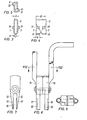
- a pair of pliers is used to open the locking element, the two front ends of the pliers legs being offset from one another are and extend only about a third of the width of the pliers, the front ends of the pliers legs are each at the edge of the pliers; and when the pliers are closed, the front ends of the pliers legs have a gap which corresponds approximately to the outer shape of the locking element; and also each front end of the pliers legs is provided with a strip-shaped thickening, the width of which is slightly smaller than the distance of the hook-shaped projections from the locking element.
- the strip-shaped thickenings engage behind the hook-shaped projections of the locking element, so that when the pliers legs are spread out, the locking element is opened and can be removed.
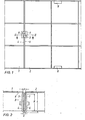
- the adjacent surface elements 1 and 2 are connected by a locking element 3 in such a way that the locking element 3 encompasses the outer webs 4 and 5 of the surface elements 1 and 2 (see FIG. 2) .
- the surface elements 1 and 2 are provided with recesses 6.
- the leg-like lugs 7 of the locking element 3 run parallel to one another, their distance A being greater than twice the wall thickness S of the outer webs 4 and 5 of the surface elements 1 and 2.
- the length L of the leg-like lugs 7 is somewhat greater than the height H of the Crosspieces 4 and 5.
- the crosspieces 4 and 5 are somewhat shortened at their upper end, so that the locking element 3 does not protrude from the surface elements 1 and 2.
- the leg-like lugs 7 of the locking element 3 are chamfered on one side in such a way that the width b of their lower edge is less than half their width B in the upper region.
- the leg-like projections 7 are each provided with a hook-shaped projection 10 and 11, the hook-shaped projections 10 and 11 being formed by an offset in the central part of the leg-like projections 7.
- each lower end 12, 13 is provided with a strip-shaped thickening 17, 18 which engages behind the hook-shaped projections 10 and 11 when the pliers are placed on the locking element 3.
Landscapes
- Engineering & Computer Science (AREA)
- Architecture (AREA)
- Civil Engineering (AREA)
- Structural Engineering (AREA)
- Mechanical Engineering (AREA)
- Mining & Mineral Resources (AREA)
- Suspension Of Electric Lines Or Cables (AREA)
- Slide Fasteners, Snap Fasteners, And Hook Fasteners (AREA)
- Clamps And Clips (AREA)
- Gripping Jigs, Holding Jigs, And Positioning Jigs (AREA)
Applications Claiming Priority (2)
| Application Number | Priority Date | Filing Date | Title |
|---|---|---|---|
| DE19823230505 DE3230505A1 (de) | 1982-08-17 | 1982-08-17 | Verriegelungselement und zange zum loesen und entfernen des verriegelungselementes |
| DE3230505 | 1982-08-17 |
Publications (3)
| Publication Number | Publication Date |
|---|---|
| EP0101599A2 true EP0101599A2 (fr) | 1984-02-29 |
| EP0101599A3 EP0101599A3 (en) | 1985-04-17 |
| EP0101599B1 EP0101599B1 (fr) | 1986-11-20 |
Family
ID=6171016
Family Applications (1)
| Application Number | Title | Priority Date | Filing Date |
|---|---|---|---|
| EP83107923A Expired EP0101599B1 (fr) | 1982-08-17 | 1983-08-11 | Elément de blocage et pinces pour le dégager et le retirer |
Country Status (3)
| Country | Link |
|---|---|
| EP (1) | EP0101599B1 (fr) |
| CA (1) | CA1218833A (fr) |
| DE (2) | DE3230505A1 (fr) |
Families Citing this family (2)
| Publication number | Priority date | Publication date | Assignee | Title |
|---|---|---|---|---|
| DE102004016848A1 (de) * | 2004-04-07 | 2005-11-03 | Iwb Ingenieurgesellschaft Mbh | Behelfsfahrbahn oder Arbeitsebene |
| CN111874792A (zh) * | 2020-07-31 | 2020-11-03 | 中国十九冶集团有限公司 | 吊装路基箱装置 |
Family Cites Families (7)
| Publication number | Priority date | Publication date | Assignee | Title |
|---|---|---|---|---|
| DE696087C (de) * | 1934-04-14 | 1940-09-11 | Rudolf Schenck Dr Ing | Metallstrasse |
| DE659068C (de) * | 1934-04-14 | 1938-04-23 | Rudolf Schenck Dr Ing | Metallstrasse |
| FR847276A (fr) * | 1938-12-08 | 1939-10-05 | Travaux Vibres | Nouvelle aire de roulement applicable particulièrement aux terrains d'aviation |
| GB560175A (en) * | 1942-02-19 | 1944-03-23 | Walter Edward Irving | Improvements in gratings more particularly for use in airfields |
| US2369412A (en) * | 1942-07-29 | 1945-02-13 | Frederick H Ruppel | Lattice mat |
| US2407059A (en) * | 1943-09-29 | 1946-09-03 | Robertson Co H H | Portable launching and landing mat for airplanes |
| DE3037809A1 (de) * | 1980-10-07 | 1982-05-06 | Estel Hoesch Werke Ag, 4600 Dortmund | Bodenbelag fuer fahrbahnen |
-
1982
- 1982-08-17 DE DE19823230505 patent/DE3230505A1/de not_active Withdrawn
-
1983
- 1983-08-11 EP EP83107923A patent/EP0101599B1/fr not_active Expired
- 1983-08-11 DE DE8383107923T patent/DE3367789D1/de not_active Expired
- 1983-08-16 CA CA000434728A patent/CA1218833A/fr not_active Expired
Also Published As
| Publication number | Publication date |
|---|---|
| EP0101599B1 (fr) | 1986-11-20 |
| DE3367789D1 (en) | 1987-01-08 |
| CA1218833A (fr) | 1987-03-10 |
| EP0101599A3 (en) | 1985-04-17 |
| DE3230505A1 (de) | 1984-02-23 |
Similar Documents
| Publication | Publication Date | Title |
|---|---|---|
| DE2448580C2 (de) | Gelaender | |
| DE1659225B2 (de) | Fachwerkträger mit Gurten aus Holzbalken und Gitterstreben aus Metall | |
| DE2237600A1 (de) | Gliederfoerderband aus gelenkig miteinander verbundenen metallischen plattengliedern | |
| DE3717877C2 (fr) | ||
| DE3301493A1 (de) | Siebboden | |
| DE2327979B2 (de) | Verfahren zur Herstellung von Plattenverbindern für Transportbänder o.dgl | |
| DE2722425A1 (de) | Anordnung zur verbindung der teile eines metallischen traggeruestes | |
| DE2727575A1 (de) | Metallgitterrost sowie verfahren und vorrichtung zu seiner herstellung | |
| DE3132977C2 (de) | Verfahren zum Herstellen eines Gitterrostes | |
| EP0101599B1 (fr) | Elément de blocage et pinces pour le dégager et le retirer | |
| DE69011489T2 (de) | Verbindungselemente für Rückenlehnen mit dazugehörigen Sitzen. | |
| EP0416201A1 (fr) | Dispositif protecteur pour espaces de rentrage sur des transporteurs de bande | |
| DE3243936A1 (de) | Fassadeneinheit | |
| DE29501159U1 (de) | Verbindungskonstruktion | |
| DE1554472B1 (de) | Vorrichtung an Regalen od.dgl. zum leicht loesbaren Verbinden eines Pfostens mit einem Tragstueck | |
| DE1673867C2 (de) | Gelenkbeschläge aus Kunststoff für Gliedermaßstäbe | |
| DE1079369B (de) | Dehnbares Gliederband | |
| DE3149054A1 (de) | Lueftungsgitter | |
| DE4340404C2 (de) | Arretierverbindung für ein gitterförmiges Schienensystem einer Hängedecke | |
| DE69407707T2 (de) | Aufhängegerippe für eine aufgehängte Decke | |
| DE7824276U1 (de) | Haltegriff | |
| DE1096582B (de) | Stabfoermiges Bauelement mit Winkelquerschnitt und regelmaessigen Reihen von Durchbrechungen | |
| DE8911351U1 (de) | Vorrichtung zur Randbegrenzung von Gerüsten u.dgl. Arbeitsplattformen | |
| DE1554472C (de) | Vorrichtung an Regalen oder dgl zum leicht losbaren Verbinden eines Pfostens mit einem Tragstuck | |
| EP0149825A2 (fr) | Conteneur, en particulier valise, avec au moins une paroi rectangulaire |
Legal Events
| Date | Code | Title | Description |
|---|---|---|---|
| PUAI | Public reference made under article 153(3) epc to a published international application that has entered the european phase |
Free format text: ORIGINAL CODE: 0009012 |
|
| AK | Designated contracting states |
Designated state(s): BE DE FR GB IT LU NL |
|
| ITCL | It: translation for ep claims filed |
Representative=s name: STUDIO JAUMANN |
|
| EL | Fr: translation of claims filed | ||
| TCNL | Nl: translation of patent claims filed | ||
| RAP1 | Party data changed (applicant data changed or rights of an application transferred) |
Owner name: HOESCH AKTIENGESELLSCHAFT |
|
| PUAL | Search report despatched |
Free format text: ORIGINAL CODE: 0009013 |
|
| AK | Designated contracting states |
Designated state(s): BE DE FR GB IT LU NL |
|
| 17P | Request for examination filed |
Effective date: 19850614 |
|
| 17Q | First examination report despatched |
Effective date: 19860122 |
|
| GRAA | (expected) grant |
Free format text: ORIGINAL CODE: 0009210 |
|
| AK | Designated contracting states |
Kind code of ref document: B1 Designated state(s): BE DE FR GB IT LU NL |
|
| ET | Fr: translation filed | ||
| REF | Corresponds to: |
Ref document number: 3367789 Country of ref document: DE Date of ref document: 19870108 |
|
| ITF | It: translation for a ep patent filed | ||
| PG25 | Lapsed in a contracting state [announced via postgrant information from national office to epo] |
Ref country code: LU Free format text: LAPSE BECAUSE OF NON-PAYMENT OF DUE FEES Effective date: 19870831 |
|
| PLBE | No opposition filed within time limit |
Free format text: ORIGINAL CODE: 0009261 |
|
| STAA | Information on the status of an ep patent application or granted ep patent |
Free format text: STATUS: NO OPPOSITION FILED WITHIN TIME LIMIT |
|
| 26N | No opposition filed | ||
| BERE | Be: lapsed |
Owner name: HOESCH A.G. Effective date: 19870831 |
|
| PG25 | Lapsed in a contracting state [announced via postgrant information from national office to epo] |
Ref country code: NL Effective date: 19880301 |
|
| NLV4 | Nl: lapsed or anulled due to non-payment of the annual fee | ||
| PG25 | Lapsed in a contracting state [announced via postgrant information from national office to epo] |
Ref country code: FR Free format text: LAPSE BECAUSE OF NON-PAYMENT OF DUE FEES Effective date: 19880429 |
|
| PG25 | Lapsed in a contracting state [announced via postgrant information from national office to epo] |
Ref country code: DE Effective date: 19880503 |
|
| GBPC | Gb: european patent ceased through non-payment of renewal fee | ||
| REG | Reference to a national code |
Ref country code: FR Ref legal event code: ST |
|
| PG25 | Lapsed in a contracting state [announced via postgrant information from national office to epo] |
Ref country code: GB Free format text: LAPSE BECAUSE OF NON-PAYMENT OF DUE FEES Effective date: 19881122 |
|
| PG25 | Lapsed in a contracting state [announced via postgrant information from national office to epo] |
Ref country code: BE Effective date: 19890831 |