EP0101623B1 - Dispositif d'appui pour un enroulement ondulé et application de ce dispositif d'appui - Google Patents
Dispositif d'appui pour un enroulement ondulé et application de ce dispositif d'appui Download PDFInfo
- Publication number
- EP0101623B1 EP0101623B1 EP83201014A EP83201014A EP0101623B1 EP 0101623 B1 EP0101623 B1 EP 0101623B1 EP 83201014 A EP83201014 A EP 83201014A EP 83201014 A EP83201014 A EP 83201014A EP 0101623 B1 EP0101623 B1 EP 0101623B1
- Authority
- EP
- European Patent Office
- Prior art keywords
- winding
- spacers
- holding device
- supporting device
- spacer
- Prior art date
- Legal status (The legal status is an assumption and is not a legal conclusion. Google has not performed a legal analysis and makes no representation as to the accuracy of the status listed.)
- Expired
Links
- 238000004804 winding Methods 0.000 title claims description 41
- 125000006850 spacer group Chemical group 0.000 claims description 45
- 239000004020 conductor Substances 0.000 claims description 8
- 239000012777 electrically insulating material Substances 0.000 claims description 2
- XLYOFNOQVPJJNP-UHFFFAOYSA-N water Substances O XLYOFNOQVPJJNP-UHFFFAOYSA-N 0.000 claims description 2
- 238000010276 construction Methods 0.000 description 3
- 238000006073 displacement reaction Methods 0.000 description 2
- 239000000110 cooling liquid Substances 0.000 description 1
- 239000008367 deionised water Substances 0.000 description 1
- 229910021641 deionized water Inorganic materials 0.000 description 1
- 239000000463 material Substances 0.000 description 1
Images


Classifications
-
- H—ELECTRICITY
- H01—ELECTRIC ELEMENTS
- H01C—RESISTORS
- H01C3/00—Non-adjustable metal resistors made of wire or ribbon, e.g. coiled, woven or formed as grids
- H01C3/02—Non-adjustable metal resistors made of wire or ribbon, e.g. coiled, woven or formed as grids arranged or constructed for reducing self-induction, capacitance or variation with frequency
-
- H—ELECTRICITY
- H01—ELECTRIC ELEMENTS
- H01C—RESISTORS
- H01C1/00—Details
- H01C1/01—Mounting; Supporting
- H01C1/014—Mounting; Supporting the resistor being suspended between and being supported by two supporting sections
-
- H—ELECTRICITY
- H01—ELECTRIC ELEMENTS
- H01C—RESISTORS
- H01C1/00—Details
- H01C1/08—Cooling, heating or ventilating arrangements
- H01C1/082—Cooling, heating or ventilating arrangements using forced fluid flow
-
- H—ELECTRICITY
- H01—ELECTRIC ELEMENTS
- H01C—RESISTORS
- H01C3/00—Non-adjustable metal resistors made of wire or ribbon, e.g. coiled, woven or formed as grids
- H01C3/10—Non-adjustable metal resistors made of wire or ribbon, e.g. coiled, woven or formed as grids the resistive element having zig-zag or sinusoidal configuration
Definitions
- the present invention relates to a mounting device according to the preamble of claim 1 and to a use of this mounting device.
- the invention relates to a prior art of mounting devices for a meandering winding, as described in GB-A-1 164 442.
- meandering preformed windings made of resistance wire are stored in elongated recesses at the end, electrically insulating spacers. Spacers between the winding ends are not provided.
- EP-AI 0 066 902 (EPC Art. 54 (3)), which is considered to be prior art, to fasten a liquid-cooled, meandering power resistor in the area of its rectilinear conductor sections in panels.
- the panels have round holes for the conductor sections so that the U-shaped bends in the power resistor cannot be pushed through.
- the invention solves the problem of eliminating the disadvantages of the known and creating a holder for a meandering winding, which ensures simple spacing of the partial conductor of the winding sufficiently and the mounting of the mounting device with the Winding facilitated.
- An advantage of the invention is that the meandering winding can be preformed and the spacers can be inserted from both sides in the longitudinal direction of the winding.
- the development according to claim 2 stabilizes the position of the end parts of the winding.
- the advantage of claim 3 lies in the space-saving construction.
- the variant according to claim 4 is also space-saving and is suitable for long windings. It enables the winding to be arranged in a cylindrical housing.
- the advantage of the embodiment according to claim 5 is that the winding only touches the spacers in small areas, whereby the spacers can be sufficiently thick for mechanical reasons.
- the development according to claim 6 enables all spacers to be fastened on a rod-shaped carrier, so that the spacers form a dimensionally stable whole with the winding even without a housing.
- Claim 7 shows an advantageous use of the mounting device according to the invention, in which case the resistor is cooled in a cooling liquid, preferably in deionized water.
- a meandering winding 1 made of round wire is shown.
- the winding 1 is provided with preformed curved parts 1 ', so that it forms anti-parallel sections and has only a low inductance as a whole when the current flows through.
- a spacer 2 was inserted from above, another spacer 3 from below.
- the spacer is provided with a hole 4 and with several elongated holes 5. Only the elongated holes 5 are made in the spacer 3.
- the mutual displacement of the elongated holes 5 is visible. This displacement enables each of the parallel sections of the winding 1 to be supported with the spacer 2 from one side and with the other spacer 3 from the other side.
- the winding 1 In the central region A of the winding 1 between the spacers 2 and 3, the winding 1 is thus carried, in the end region B the winding 1 is without support.
- the length of the areas A and B depends on the mechanical strength of the specific winding 1, the material, the wire cross section and the winding spacing to be observed in particular.
- the right part of FIG. 1 shows the variant in which the right end of the winding 1 is also guided through the upper spacer 2.
- the hole for this end is labeled 4 '.
- the spacers can be perforated in different ways, e.g. is shown in Fig. 1, they can also be carried out the same way, where they are used mutually in reverse.
- FIG. 2 shows a view of the upper spacer 2 and in FIG. 3 the lower spacer 3.
- the middle parts in Figs. 1 to 3 have been omitted.
- FIG. 4 shows a variant which essentially corresponds to that according to FIG. 1, but in which, for mechanical reasons, two upper spacers 2 and two lower spacers 3 are arranged.
- spacers 6 and 7 are illustrated, which are intended for a three-day winding 1.
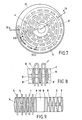
- FIG. 7 shows a spacer 8 for a spiral mounting of the meandering winding 1. This winding 1 is not shown in FIG. 7.
- the spacer 8 is disc-shaped in this exemplary embodiment and is provided with a fastening opening 10. By means of this fastening opening, two or more spacers 8 can be fastened on a rod-shaped carrier.
- the elongated holes 5 each have a taper 9 in the central zones, so that the outer cross sections of the holes 5 are larger than the inner cross section. This construction facilitates assembly, the contact area of the winding 1 with the spacer 8 remaining small.
- FIG. 9 The section IX-IX from FIG. 7 is illustrated in FIG. 9. This section runs perpendicular to the section VIII-VIII shown in FIG. 8. Parts of the winding 1 are shown in the left part, the taper 9 of the elongated holes 5 is clearly shown in the right part.
Landscapes
- Engineering & Computer Science (AREA)
- Microelectronics & Electronic Packaging (AREA)
- Physics & Mathematics (AREA)
- Fluid Mechanics (AREA)
- Coils Or Transformers For Communication (AREA)
- Insulating Of Coils (AREA)
Claims (7)
Applications Claiming Priority (2)
| Application Number | Priority Date | Filing Date | Title |
|---|---|---|---|
| CH491382 | 1982-08-17 | ||
| CH4913/82 | 1982-08-17 |
Publications (2)
| Publication Number | Publication Date |
|---|---|
| EP0101623A1 EP0101623A1 (fr) | 1984-02-29 |
| EP0101623B1 true EP0101623B1 (fr) | 1987-03-11 |
Family
ID=4284712
Family Applications (1)
| Application Number | Title | Priority Date | Filing Date |
|---|---|---|---|
| EP83201014A Expired EP0101623B1 (fr) | 1982-08-17 | 1983-07-07 | Dispositif d'appui pour un enroulement ondulé et application de ce dispositif d'appui |
Country Status (2)
| Country | Link |
|---|---|
| EP (1) | EP0101623B1 (fr) |
| DE (1) | DE3370230D1 (fr) |
Families Citing this family (5)
| Publication number | Priority date | Publication date | Assignee | Title |
|---|---|---|---|---|
| DE4008422A1 (de) * | 1990-03-16 | 1991-09-19 | Asea Brown Boveri | Leistungswiderstand |
| DE4112677A1 (de) * | 1991-04-18 | 1992-10-22 | Asea Brown Boveri | Elektrischer widerstand |
| GB2323479A (en) * | 1997-03-19 | 1998-09-23 | Eaton Ltd | Mounting resistor elements |
| CN101944414B (zh) * | 2010-08-09 | 2012-10-10 | 华中科技大学 | 高功率脉冲线性假负载 |
| DE102011100760A1 (de) * | 2011-05-07 | 2012-11-08 | Walter Marks | Steuereinrichtung und Verfahren zum Ansteuern eines Halbleiterschalters |
Citations (1)
| Publication number | Priority date | Publication date | Assignee | Title |
|---|---|---|---|---|
| US2640092A (en) * | 1949-11-17 | 1953-05-26 | Us Navy | Low reactance shunt |
Family Cites Families (2)
| Publication number | Priority date | Publication date | Assignee | Title |
|---|---|---|---|---|
| GB1164442A (en) * | 1965-07-21 | 1969-09-17 | Reyrolle A & Co Ltd | Improvements in or relating to Air-Cooled Electrical Resistance Assemblies |
| EP0066902B1 (fr) * | 1981-05-21 | 1985-11-21 | BBC Aktiengesellschaft Brown, Boveri & Cie. | Résistance de puissance refroidie par liquide et son application |
-
1983
- 1983-07-07 EP EP83201014A patent/EP0101623B1/fr not_active Expired
- 1983-07-07 DE DE8383201014T patent/DE3370230D1/de not_active Expired
Patent Citations (1)
| Publication number | Priority date | Publication date | Assignee | Title |
|---|---|---|---|---|
| US2640092A (en) * | 1949-11-17 | 1953-05-26 | Us Navy | Low reactance shunt |
Also Published As
| Publication number | Publication date |
|---|---|
| DE3370230D1 (en) | 1987-04-16 |
| EP0101623A1 (fr) | 1984-02-29 |
Similar Documents
| Publication | Publication Date | Title |
|---|---|---|
| DE2263260C3 (de) | Heizkörper für gebläsebetriebene Heizgeräte, insbesondere Kleinheizkörper für Haartrockner o.dgl. | |
| DE19740224A1 (de) | Drehbare Verbindungsvorrichtung zur Verbindung von Kabeln | |
| DE69022899T2 (de) | Sammelschiene für elektrische Stromversorgung. | |
| EP0101623B1 (fr) | Dispositif d'appui pour un enroulement ondulé et application de ce dispositif d'appui | |
| DE2705526C3 (de) | Elektrisches Heizelement für gasförmige Medien | |
| DE102019126168B4 (de) | Widerstandsanordnung für stufenschalter und stufenschalter | |
| DE10316908A1 (de) | Heizvorrichtung | |
| EP1575076B1 (fr) | Porte-fusible pour des fusibles plats | |
| DE2931000C2 (de) | Stufenschalter für Stufentransformatoren mit einem Träger für Polungswiderstände | |
| EP0289707B1 (fr) | Elément chauffant électrique avec prise | |
| DE1765392C3 (de) | Widerstandselement für Hochstrom Widerstandseinheiten | |
| DE2500223C3 (de) | Elektrisches Widerstandsgerät | |
| DE1539671A1 (de) | Thyristorventil | |
| DE890378C (de) | Elektrischer Widerstand, insbesondere fuer Lastschalter | |
| DE620526C (de) | Induktionsspule mit veraenderlichem Rauminhalt, insbesondere fuer kernlose Induktionsoefen | |
| EP1041587B1 (fr) | Transformateur, convertisseur ou inductance avec bobines en disque et procédé de fabrication d'un tel composant | |
| DE2339437C3 (de) | Aufnahmevorrichtung mit Bandverkabelung | |
| DE2849258A1 (de) | Elektrischer heizkoerper fuer fluide medien | |
| DE1936543B2 (de) | Vorrichtung zur kontinuierlichen Veränderung des Laufzeitverhaltens von der Nachrichtenübertragung dienenden Laufzeitentzerrungsgliedern | |
| DE1021088B (de) | Spanngitter fuer elektrische Entladungsgefaesse | |
| DE594572C (de) | Elektrische, rohrfoermige Heizvorrichtung | |
| DE19808667C2 (de) | Gebogene Elektrode | |
| DE2652087A1 (de) | Widerstandsheizelement und daraus hergestelltes heizregister | |
| DE3100169C2 (fr) | ||
| DE1297252B (de) | Elektrischer Gaserhitzer |
Legal Events
| Date | Code | Title | Description |
|---|---|---|---|
| PUAI | Public reference made under article 153(3) epc to a published international application that has entered the european phase |
Free format text: ORIGINAL CODE: 0009012 |
|
| AK | Designated contracting states |
Designated state(s): CH DE FR LI SE |
|
| 17P | Request for examination filed |
Effective date: 19840601 |
|
| GRAA | (expected) grant |
Free format text: ORIGINAL CODE: 0009210 |
|
| AK | Designated contracting states |
Kind code of ref document: B1 Designated state(s): CH DE FR LI SE |
|
| REF | Corresponds to: |
Ref document number: 3370230 Country of ref document: DE Date of ref document: 19870416 |
|
| ET | Fr: translation filed | ||
| RAP2 | Party data changed (patent owner data changed or rights of a patent transferred) |
Owner name: BBC BROWN BOVERI AG |
|
| PLBE | No opposition filed within time limit |
Free format text: ORIGINAL CODE: 0009261 |
|
| STAA | Information on the status of an ep patent application or granted ep patent |
Free format text: STATUS: NO OPPOSITION FILED WITHIN TIME LIMIT |
|
| 26N | No opposition filed | ||
| EAL | Se: european patent in force in sweden |
Ref document number: 83201014.4 |
|
| PGFP | Annual fee paid to national office [announced via postgrant information from national office to epo] |
Ref country code: CH Payment date: 19970722 Year of fee payment: 15 |
|
| PG25 | Lapsed in a contracting state [announced via postgrant information from national office to epo] |
Ref country code: LI Free format text: LAPSE BECAUSE OF NON-PAYMENT OF DUE FEES Effective date: 19980731 Ref country code: CH Free format text: LAPSE BECAUSE OF NON-PAYMENT OF DUE FEES Effective date: 19980731 |
|
| REG | Reference to a national code |
Ref country code: CH Ref legal event code: PL |
|
| PGFP | Annual fee paid to national office [announced via postgrant information from national office to epo] |
Ref country code: SE Payment date: 20000626 Year of fee payment: 18 |
|
| PGFP | Annual fee paid to national office [announced via postgrant information from national office to epo] |
Ref country code: FR Payment date: 20000629 Year of fee payment: 18 Ref country code: DE Payment date: 20000629 Year of fee payment: 18 |
|
| PG25 | Lapsed in a contracting state [announced via postgrant information from national office to epo] |
Ref country code: SE Free format text: LAPSE BECAUSE OF NON-PAYMENT OF DUE FEES Effective date: 20010708 |
|
| EUG | Se: european patent has lapsed |
Ref document number: 83201014.4 |
|
| PG25 | Lapsed in a contracting state [announced via postgrant information from national office to epo] |
Ref country code: FR Free format text: LAPSE BECAUSE OF NON-PAYMENT OF DUE FEES Effective date: 20020329 |
|
| PG25 | Lapsed in a contracting state [announced via postgrant information from national office to epo] |
Ref country code: DE Free format text: LAPSE BECAUSE OF NON-PAYMENT OF DUE FEES Effective date: 20020501 |
|
| REG | Reference to a national code |
Ref country code: FR Ref legal event code: ST |