EP0101637A2 - Trémie pour matières en vrac - Google Patents
Trémie pour matières en vrac Download PDFInfo
- Publication number
- EP0101637A2 EP0101637A2 EP83201200A EP83201200A EP0101637A2 EP 0101637 A2 EP0101637 A2 EP 0101637A2 EP 83201200 A EP83201200 A EP 83201200A EP 83201200 A EP83201200 A EP 83201200A EP 0101637 A2 EP0101637 A2 EP 0101637A2
- Authority
- EP
- European Patent Office
- Prior art keywords
- operating handle
- bulk bin
- bin according
- screen unit
- roller screen
- Prior art date
- Legal status (The legal status is an assumption and is not a legal conclusion. Google has not performed a legal analysis and makes no representation as to the accuracy of the status listed.)
- Granted
Links
- 230000003028 elevating effect Effects 0.000 abstract 1
- 238000010276 construction Methods 0.000 description 2
- 238000012986 modification Methods 0.000 description 2
- 230000004048 modification Effects 0.000 description 2
- 239000011435 rock Substances 0.000 description 2
- 235000002595 Solanum tuberosum Nutrition 0.000 description 1
- 244000061456 Solanum tuberosum Species 0.000 description 1
- 230000005540 biological transmission Effects 0.000 description 1
- 230000008878 coupling Effects 0.000 description 1
- 238000010168 coupling process Methods 0.000 description 1
- 238000005859 coupling reaction Methods 0.000 description 1
- 238000007599 discharging Methods 0.000 description 1
- 239000000463 material Substances 0.000 description 1
- 235000012015 potatoes Nutrition 0.000 description 1
- 230000002035 prolonged effect Effects 0.000 description 1
- 239000002689 soil Substances 0.000 description 1
Images


Classifications
-
- B—PERFORMING OPERATIONS; TRANSPORTING
- B07—SEPARATING SOLIDS FROM SOLIDS; SORTING
- B07B—SEPARATING SOLIDS FROM SOLIDS BY SIEVING, SCREENING, SIFTING OR BY USING GAS CURRENTS; SEPARATING BY OTHER DRY METHODS APPLICABLE TO BULK MATERIAL, e.g. LOOSE ARTICLES FIT TO BE HANDLED LIKE BULK MATERIAL
- B07B1/00—Sieving, screening, sifting, or sorting solid materials using networks, gratings, grids, or the like
- B07B1/46—Constructional details of screens in general; Cleaning or heating of screens
- B07B1/4609—Constructional details of screens in general; Cleaning or heating of screens constructional details of screening surfaces or meshes
- B07B1/4636—Regulation of screen apertures
-
- A—HUMAN NECESSITIES
- A01—AGRICULTURE; FORESTRY; ANIMAL HUSBANDRY; HUNTING; TRAPPING; FISHING
- A01D—HARVESTING; MOWING
- A01D17/00—Digging machines with sieving and conveying mechanisms
- A01D17/06—Digging machines with sieving and conveying mechanisms with rollers or disc screens
-
- B—PERFORMING OPERATIONS; TRANSPORTING
- B07—SEPARATING SOLIDS FROM SOLIDS; SORTING
- B07B—SEPARATING SOLIDS FROM SOLIDS BY SIEVING, SCREENING, SIFTING OR BY USING GAS CURRENTS; SEPARATING BY OTHER DRY METHODS APPLICABLE TO BULK MATERIAL, e.g. LOOSE ARTICLES FIT TO BE HANDLED LIKE BULK MATERIAL
- B07B1/00—Sieving, screening, sifting, or sorting solid materials using networks, gratings, grids, or the like
- B07B1/12—Apparatus having only parallel elements
- B07B1/14—Roller screens
-
- B—PERFORMING OPERATIONS; TRANSPORTING
- B07—SEPARATING SOLIDS FROM SOLIDS; SORTING
- B07B—SEPARATING SOLIDS FROM SOLIDS BY SIEVING, SCREENING, SIFTING OR BY USING GAS CURRENTS; SEPARATING BY OTHER DRY METHODS APPLICABLE TO BULK MATERIAL, e.g. LOOSE ARTICLES FIT TO BE HANDLED LIKE BULK MATERIAL
- B07B1/00—Sieving, screening, sifting, or sorting solid materials using networks, gratings, grids, or the like
- B07B1/46—Constructional details of screens in general; Cleaning or heating of screens
- B07B1/50—Cleaning
Definitions
- This invention relates to a bulk bin for agricultural products, comprising a conveyor bottom slanting upwardly and capable, in operation, of conveying agricultural products charged into the bin upwards, a roller screen unit onto which, in operation, the products are deposited by the conveyor bottom, and a product-discharge device disposed downstream of said roller screen unit.
- the roller screen unit which serves to remove earth, rocks, undersize products and the like, consists of a plurality of spaced, side-by-side, drivable rollers extending transversely to the direction of transport of the conveyor bottom.
- the prior roller screen unit is further provided with means for adjusting the interspace between the individual rollers of the roller screen unit.
- roller screen unit effectively separates earth, rocks, undersize products and the like from the agricultural products, for example potatoes
- a bulk bin of the kind described is characterized by means for continuously varying the spacing between the rollers of the roller screen unit during operation.
- the bulk bin shown diagrammatically in Fig. 1 in side-elevational view comprises a frame 1, which is mobile owing to the provision of wheels 2 and a drawbar 3.
- the bulk bin proper is formed by upright sidewalls 4,4', between which is disposed an endless conveyor bottom, the bottom return run of which is designated by 5.
- the conveyor bottom is driven by a drive unit 6 arranged adjacent to the upper end of the elevation path.
- a roller screen unit Disposed beyond the upper end of the elevation path is a roller screen unit, diagrammatically shown at 7, and shown in more detail in Figs. 2 and 3.
- a transverse conveyor 8 Disposed underneath the roller screen unit is a transverse conveyor 8 for discharging material passed by the roller screen unit.
- the rollers of the roller screen unit are driven in such a manner that the produce is transported by the rollers to a second transverse conveyor 9, capable of transporting the produce further.
- Fig. 2 shows a diagrammatic exploded view of the roller screen unit.
- the unit comprises a plurality of rollers 10, each provided with a sprocket 11 capable of cooperating with a drive chain 35, shown in Fig. 3, and arranged to rotate the rollers.
- the shafts of the rollers are secured at both ends to the free ends of strips 12-16, of various lengths, and together with a connecting strip 17 forming a linkage 18.
- One end 19 of the connecting strip is fixedly, but pivotally connected to a fixed frame member 20. In the embodiment shown, this end 19 is adjacent to the roller located closest to the conveyor bottom (on the right-hand side in Fig. 2).
- the adjustment of the mutual spacing between the rollers is effected by moving the shaft of one of the other rollers, preferably the shaft of the roller located closest to the product conveyor 9 (on the left-hand side of Fig. 2) transversely to its longitudinal direction. Owing to the operation of the linkage the other rollers will then be moved as well, and the interspace is changed.
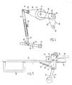
- Fig. 3 shows the handle for adjusting the roller spacing.
- Handle 21 is secured at one end to a shaft 22 carrying a fixed pinion 23 arranged to cooperate with a rack 25, constituted in this case by a length of chain secured to a girder 26 of the frame.
- Handle 21 is arranged to pivot relative to a bearing block 27 secured to shaft 22, in a plane containing the shaft. So long as the handle is in its inoperative position, a pin secured to the handle engages with a cogwheel 29 also fixedlysecured to shaft 22, and the shaft can be turned by turning the handle according to the double arrow 28. If, however, the handle is pulled outwards in the plane referred to, the pin is no longer in engagement with cogwheel 29, and the handle is capable of being freely rotated relatively to shaft 22 and cogwheel 29.
- pinion 23 rolls on rack 25, thereby taking along shaft 22 transversely to its longitudinal direction.
- Shaft 22 is journalled in a transverse girder 30, provided at its ends with projections 31 carrying rollers 32 which fall into a profile of girder 26.
- Girder 30 forms part of a subframe carrying forks 34 coinciding with the shaft of the front roller.
- subframe 33 with the forks is moved relatively to the fixed frame members 20, so that the front roller and, via the linkage, also the other rollers, are moved relatively to the rearmost roller, so that the interspace between the rollers is changed.
- Fig. 3 further shows drive chains 35 for the rollers, and a drive motor 36.
- the spacing between the rollers is continuously varied during operation, because experiments have surprisingly shown that this minimizes the chance of the roller screen unit becoming clogged.
- Such a continuous variation of the roller spacing in a roller screen unit can be accomplished in various ways.
- Fig. 4 shows, by way of example, one of the possible embodiments.
- the drive unit indicated at 6 in Fig. 1 is shown at 40 in Fig. 4.
- the drive unit comprises a first driven pulley 41, which via a belt 42 drives a larger pulley 43.
- a sprocket 48 mounted in accordance with the present invention on an outwardly prolonged shaft 47, is driven. In operation, this sprocket drives, via a chain 49, a second, smaller sprocket 50 to produce the desired rotary velocity.
- sprocket 50 Secured to sprocket 50 is an eccentric crank 51, which is connected to a crank arm 52, which in turn is connected to operating handle 21. Accordingly, when the drive unit is in operation, the operating handle is continuously moved up and down, as indicated by a double arrow 53 in Fig. 4. As a result the spacing between the rollers of the roller screen unit is continuously varied as well.
- the operating handle now designated by 54, is, in operation, coupled with sprocket 29, which is fixedly secured to the shaft, by means of a pin extending between the teeth of the sprocket.
- the handle is no longer capable of being moved outwards, pivoting in the plane of shaft 23. Accordingly, the operating handle is modified, in a manner to be described hereinafter in order that it may yet be disengaged from sprocket 29.
- the initial spacing of the rollers can be adjusted.
- the accuracy of this adjustment is determined by the pitch of the teeth of sprocket 29.
- crank arm 52 with an arm member 55 that is adjustable relatively to the part secured to crank 51.
- the adjustable arm member falls in a hollow portion of the part secured to the crank, in which it can be fixed in a desired position by means of a winged bolt 56.
- operating handle 54 is provided with a plurality of holes 57. By selecting one of these holes as the point of attachment of crank arm member 55, the initial stroke length of the rollers can be adjusted.
- the operating handle modified in accordance with the present invention is shown in more detail in plan view in Fig. 5.
- Operating handle 54 is provided with a grip 58 and with a bearing block 59 falling around shaft 22.
- the sprocket 29, mounted on shaft 22, is shown in dotted lines.
- the uncoupling mechanism comprises a plate member 61, extending transversely to the operating handle, and provided with a bore to receive shaft 60.
- Plate member 61 carries at its one end remote from the operating handle a grip 62 which via a tension spring 63 is connected to the operating handle. Plate member 61 is provided at its other end with a pin 64 normally falling between two teeth of sprocket 29 under the influence of tension spring 63. However, by moving grip 62 in the direction of arrow 65, pin 64 can be brought out of engagement with sprocket 29.
- the pin can then be placed between two other teeth of the sprocket to vary the initial spacing between the rollers.
- this construction serves as a safeguard. If, for example, a hard obstacle is present between the rollers, shaft 22 and hence sprocket 29, is unable to complete the stroke set. In that case, however, pin 64 is capable of sliding over the teeth of the sprocket, thereby extending spring 63, so that any damage to the rollers or other structural parts is prevented.
- the uncoupling mechanism is further provided with a plate-shaped extension 66, secured to the first plate member 61, and disposed slightly above the body of the operating handle, which pro - jection is provided with a vertical, threaded bore 67 to receive a winged bolt or like member. By means of this winged bolt the uncoupling mechanism can be fixed in the uncoupled position.
Landscapes
- Life Sciences & Earth Sciences (AREA)
- Environmental Sciences (AREA)
- Combined Means For Separation Of Solids (AREA)
- Soil Working Implements (AREA)
- Rollers For Roller Conveyors For Transfer (AREA)
Applications Claiming Priority (2)
| Application Number | Priority Date | Filing Date | Title |
|---|---|---|---|
| NL8203244 | 1982-08-18 | ||
| NL8203244A NL8203244A (nl) | 1982-08-18 | 1982-08-18 | Stortbunker. |
Publications (3)
| Publication Number | Publication Date |
|---|---|
| EP0101637A2 true EP0101637A2 (fr) | 1984-02-29 |
| EP0101637A3 EP0101637A3 (en) | 1984-03-28 |
| EP0101637B1 EP0101637B1 (fr) | 1987-07-22 |
Family
ID=19840152
Family Applications (1)
| Application Number | Title | Priority Date | Filing Date |
|---|---|---|---|
| EP19830201200 Expired EP0101637B1 (fr) | 1982-08-18 | 1983-08-17 | Trémie pour matières en vrac |
Country Status (3)
| Country | Link |
|---|---|
| EP (1) | EP0101637B1 (fr) |
| DE (1) | DE3372588D1 (fr) |
| NL (1) | NL8203244A (fr) |
Cited By (7)
| Publication number | Priority date | Publication date | Assignee | Title |
|---|---|---|---|---|
| GB2160124A (en) * | 1984-06-08 | 1985-12-18 | Tickhill Eng Co Ltd | Grading apparatus |
| EP0418981A1 (fr) * | 1989-09-21 | 1991-03-27 | Zijlstra & Bolhuis B.V. | Crible à rouleaux |
| EP0435359A1 (fr) * | 1989-11-24 | 1991-07-03 | Zijlstra & Bolhuis B.V. | Trémie pour des produits agricoles |
| EP0410808A3 (en) * | 1989-07-28 | 1991-07-31 | Richard Pearson Limited | A lifting conveyor, and an agricultural separator incorporating a lifting conveyor |
| EP0501590A1 (fr) * | 1991-02-28 | 1992-09-02 | Zijlstra & Bolhuis B.V. | Trémie pour des produits agricoles |
| AU695192B2 (en) * | 1994-06-22 | 1998-08-06 | Technix Bitumen Limited | Transportable container |
| NL1016185C2 (nl) * | 2000-09-14 | 2002-03-15 | Ploeger Agro B V | Inrichting voor het gelijktijdig reinigen en transporteren van bol- of knolgewassen en zelfrijdende rooi-inrichting. |
Family Cites Families (7)
| Publication number | Priority date | Publication date | Assignee | Title |
|---|---|---|---|---|
| US3023904A (en) * | 1954-03-15 | 1962-03-06 | Brueckenbau Flender Gmbh | Screen for use in oscillating screening devices |
| FR1491435A (fr) * | 1966-06-28 | 1967-08-11 | Const De Machines Agricoles Et | Dispositif pour le nettoyage de pommes de terre et tubercules analogues |
| AU468224B2 (en) * | 1969-05-19 | 1975-12-10 | Jacob Donges And Walter Harold Donges | Roller adjustment mechanism |
| US3721345A (en) * | 1971-05-06 | 1973-03-20 | Milestone Inc | Method and machine for selecting potatoes of given size from massed potatoes of random size |
| SE406280B (sv) * | 1977-10-03 | 1979-02-05 | Luossavaara Kiirunavaara Ab | Sikt |
| DE2946312A1 (de) * | 1979-11-16 | 1981-05-27 | Günter 2148 Zeven Gerlach | Vorrichtung zum trennen fester stoffe unterschiedlicher groesse voneinander, insbesondere zum absondern von sand, kraut etc. von zuckerrueben, ruebenschwaenzen o.dgl. |
| DE3027651A1 (de) * | 1980-07-22 | 1982-03-18 | Gebr. Bütfering Maschinenfabrik, 4720 Beckum | Vorrichtung zum trennen eines ruebenstromes in zwei teilstroeme |
-
1982
- 1982-08-18 NL NL8203244A patent/NL8203244A/nl not_active Application Discontinuation
-
1983
- 1983-08-17 DE DE8383201200T patent/DE3372588D1/de not_active Expired
- 1983-08-17 EP EP19830201200 patent/EP0101637B1/fr not_active Expired
Cited By (7)
| Publication number | Priority date | Publication date | Assignee | Title |
|---|---|---|---|---|
| GB2160124A (en) * | 1984-06-08 | 1985-12-18 | Tickhill Eng Co Ltd | Grading apparatus |
| EP0410808A3 (en) * | 1989-07-28 | 1991-07-31 | Richard Pearson Limited | A lifting conveyor, and an agricultural separator incorporating a lifting conveyor |
| EP0418981A1 (fr) * | 1989-09-21 | 1991-03-27 | Zijlstra & Bolhuis B.V. | Crible à rouleaux |
| EP0435359A1 (fr) * | 1989-11-24 | 1991-07-03 | Zijlstra & Bolhuis B.V. | Trémie pour des produits agricoles |
| EP0501590A1 (fr) * | 1991-02-28 | 1992-09-02 | Zijlstra & Bolhuis B.V. | Trémie pour des produits agricoles |
| AU695192B2 (en) * | 1994-06-22 | 1998-08-06 | Technix Bitumen Limited | Transportable container |
| NL1016185C2 (nl) * | 2000-09-14 | 2002-03-15 | Ploeger Agro B V | Inrichting voor het gelijktijdig reinigen en transporteren van bol- of knolgewassen en zelfrijdende rooi-inrichting. |
Also Published As
| Publication number | Publication date |
|---|---|
| DE3372588D1 (de) | 1987-08-27 |
| NL8203244A (nl) | 1984-03-16 |
| EP0101637B1 (fr) | 1987-07-22 |
| EP0101637A3 (en) | 1984-03-28 |
Similar Documents
| Publication | Publication Date | Title |
|---|---|---|
| US4147017A (en) | Tomato harvester | |
| US5697451A (en) | Crop cleaner | |
| EP0101637A2 (fr) | Trémie pour matières en vrac | |
| US3942307A (en) | Billet elevator for sugar cane harvesters | |
| US6182832B1 (en) | Easy-to-adjust grader | |
| US3070944A (en) | Harvesting apparatus | |
| EP0678234A1 (fr) | Nettoyeur de récolte | |
| US3976214A (en) | Sugar cane planter | |
| US4759680A (en) | Apparatus for separating a crop from a continuous tray | |
| US3739854A (en) | Device for harvesting cabbage | |
| US4369871A (en) | Elevator conveyor for tomatoes or the like | |
| GB2067434A (en) | Potato harvester | |
| DE69816754T2 (de) | Landwirtschaftliche Maschine mit Aufzugsystem | |
| US4243346A (en) | Unloader for taking feed from a horizontal silo | |
| NL8103928A (nl) | Inrichting voor het reinigen en transporteren van bol-, wortel- en knolgewassen. | |
| US3237390A (en) | Endless belt side delivery rake | |
| US4122901A (en) | Unpowered support vehicle | |
| US2841103A (en) | Sugar cane planter | |
| JP3009590U (ja) | 玉葱の根切り土振るい装置 | |
| US4218070A (en) | Unpowered support vehicle | |
| EP0501590A1 (fr) | Trémie pour des produits agricoles | |
| US2013409A (en) | Potato digging and sorting machine | |
| US1279793A (en) | Potato-digger. | |
| DE2900139B2 (de) | Walzenförderer | |
| EP0435359B1 (fr) | Trémie pour des produits agricoles |
Legal Events
| Date | Code | Title | Description |
|---|---|---|---|
| PUAI | Public reference made under article 153(3) epc to a published international application that has entered the european phase |
Free format text: ORIGINAL CODE: 0009012 |
|
| PUAL | Search report despatched |
Free format text: ORIGINAL CODE: 0009013 |
|
| AK | Designated contracting states |
Designated state(s): BE DE FR GB NL |
|
| AK | Designated contracting states |
Designated state(s): BE DE FR GB NL |
|
| 17P | Request for examination filed |
Effective date: 19840201 |
|
| GRAA | (expected) grant |
Free format text: ORIGINAL CODE: 0009210 |
|
| AK | Designated contracting states |
Kind code of ref document: B1 Designated state(s): BE DE FR GB NL |
|
| REF | Corresponds to: |
Ref document number: 3372588 Country of ref document: DE Date of ref document: 19870827 |
|
| ET | Fr: translation filed | ||
| PLBE | No opposition filed within time limit |
Free format text: ORIGINAL CODE: 0009261 |
|
| STAA | Information on the status of an ep patent application or granted ep patent |
Free format text: STATUS: NO OPPOSITION FILED WITHIN TIME LIMIT |
|
| 26N | No opposition filed | ||
| REG | Reference to a national code |
Ref country code: FR Ref legal event code: ST |
|
| REG | Reference to a national code |
Ref country code: FR Ref legal event code: RC |
|
| PGFP | Annual fee paid to national office [announced via postgrant information from national office to epo] |
Ref country code: FR Payment date: 19980720 Year of fee payment: 16 |
|
| PGFP | Annual fee paid to national office [announced via postgrant information from national office to epo] |
Ref country code: GB Payment date: 19980810 Year of fee payment: 16 |
|
| PGFP | Annual fee paid to national office [announced via postgrant information from national office to epo] |
Ref country code: DE Payment date: 19980925 Year of fee payment: 16 |
|
| PG25 | Lapsed in a contracting state [announced via postgrant information from national office to epo] |
Ref country code: GB Free format text: LAPSE BECAUSE OF NON-PAYMENT OF DUE FEES Effective date: 19990817 |
|
| GBPC | Gb: european patent ceased through non-payment of renewal fee |
Effective date: 19990817 |
|
| PG25 | Lapsed in a contracting state [announced via postgrant information from national office to epo] |
Ref country code: FR Free format text: LAPSE BECAUSE OF NON-PAYMENT OF DUE FEES Effective date: 20000428 |
|
| PG25 | Lapsed in a contracting state [announced via postgrant information from national office to epo] |
Ref country code: DE Free format text: LAPSE BECAUSE OF NON-PAYMENT OF DUE FEES Effective date: 20000601 |
|
| PGFP | Annual fee paid to national office [announced via postgrant information from national office to epo] |
Ref country code: BE Payment date: 20000713 Year of fee payment: 18 |
|
| REG | Reference to a national code |
Ref country code: FR Ref legal event code: ST |
|
| PGFP | Annual fee paid to national office [announced via postgrant information from national office to epo] |
Ref country code: NL Payment date: 20000831 Year of fee payment: 18 |
|
| PG25 | Lapsed in a contracting state [announced via postgrant information from national office to epo] |
Ref country code: BE Free format text: LAPSE BECAUSE OF NON-PAYMENT OF DUE FEES Effective date: 20010831 |
|
| BERE | Be: lapsed |
Owner name: ZIJLSTRA & BOLHUIS B.V. Effective date: 20010831 |
|
| PG25 | Lapsed in a contracting state [announced via postgrant information from national office to epo] |
Ref country code: NL Free format text: LAPSE BECAUSE OF NON-PAYMENT OF DUE FEES Effective date: 20020301 |
|
| NLV4 | Nl: lapsed or anulled due to non-payment of the annual fee |
Effective date: 20020301 |