EP0101647B1 - Geformtes Auslagetablett - Google Patents
Geformtes Auslagetablett Download PDFInfo
- Publication number
- EP0101647B1 EP0101647B1 EP83304666A EP83304666A EP0101647B1 EP 0101647 B1 EP0101647 B1 EP 0101647B1 EP 83304666 A EP83304666 A EP 83304666A EP 83304666 A EP83304666 A EP 83304666A EP 0101647 B1 EP0101647 B1 EP 0101647B1
- Authority
- EP
- European Patent Office
- Prior art keywords
- shelf
- flange
- tubular
- knock
- post
- Prior art date
- Legal status (The legal status is an assumption and is not a legal conclusion. Google has not performed a legal analysis and makes no representation as to the accuracy of the status listed.)
- Expired
Links
- 230000003014 reinforcing effect Effects 0.000 claims description 18
- 238000003197 gene knockdown Methods 0.000 claims description 15
- 239000004033 plastic Substances 0.000 claims description 10
- 230000002093 peripheral effect Effects 0.000 claims description 9
- 230000004323 axial length Effects 0.000 claims description 5
- 230000002787 reinforcement Effects 0.000 claims description 5
- 238000005452 bending Methods 0.000 claims description 3
- 230000009545 invasion Effects 0.000 claims description 3
- 238000010276 construction Methods 0.000 description 10
- 125000006850 spacer group Chemical group 0.000 description 4
- 239000000463 material Substances 0.000 description 2
- 239000002991 molded plastic Substances 0.000 description 2
- 238000005299 abrasion Methods 0.000 description 1
- 230000007547 defect Effects 0.000 description 1
- 230000003292 diminished effect Effects 0.000 description 1
- 230000000694 effects Effects 0.000 description 1
- 239000012634 fragment Substances 0.000 description 1
- 238000009432 framing Methods 0.000 description 1
- 238000000465 moulding Methods 0.000 description 1
Images

Classifications
-
- A—HUMAN NECESSITIES
- A47—FURNITURE; DOMESTIC ARTICLES OR APPLIANCES; COFFEE MILLS; SPICE MILLS; SUCTION CLEANERS IN GENERAL
- A47B—TABLES; DESKS; OFFICE FURNITURE; CABINETS; DRAWERS; GENERAL DETAILS OF FURNITURE
- A47B87/00—Sectional furniture, i.e. combinations of complete furniture units, e.g. assemblies of furniture units of the same kind such as linkable cabinets, tables, racks or shelf units
- A47B87/02—Sectional furniture, i.e. combinations of complete furniture units, e.g. assemblies of furniture units of the same kind such as linkable cabinets, tables, racks or shelf units stackable ; stackable and linkable
- A47B87/0207—Stackable racks, trays or shelf units
- A47B87/0223—Shelves stackable by means of poles or tubular members as distance-holders therebetween
Definitions
- This invention relates to an improved shelf for a knock-down display stand that is formed from a plurality of molded plastic shelves that are spaced apart vertically by lightweight tubular posts which, together with sleeve parts, formed integrally on the plastic shelves, provide the vertical structural uprights for the display stand.
- a plurality of molded plastic shelves having quasi-rectangular, generally planar, plastic, integrally-formed object-supporting shelf members with integral sleeves thereon that are designed to be adapted to telescopically co-operate with light-weight tubular posts which, when assembled, with the shelves, provides the vertical structural upright supports for the display stand.
- the shelf members are each formed integral with transversely extending tubular elements that provide sleeve-like mounting members at the corners of the shelf which have invaded and thereby diminished the intended rectangular support surface of the support member.
- Such display stands have also had shelf members which are formed integrally with a transverse planar flange that extended transversely along, and integral with, the exposed horizontal edges of the support member, and merged with the sleeve-like members in vertical traces that were located substantially radially of the center of the sleeve-like members. Because of the geometry of such shelves, the entire support area of the shelf could not be utilized, as a quadrant of each sleeve-like member occupied a corner of the shelf. Furthermore, the shelf constructions required substantial reinforcement on the underside of the support surface to withstand the product-load forces applied thereon, and to withstand the stresses developed therein and therefore the material forming the shelves is used in an inefficient manner, thus failing to provide maximum cost effectiveness of construction.
- plastic structural members such as the rectangular-shaped peripheral flange referred to above to be formed as channel-members, having a U-shaped cross section.
- One object of the present invention is to provide an improved plastic shelf for a knock-down display stand, which shelf is characterised by economy of use of the plastic material to form same, and which provides a shelf having a full rectangular support surface and improved resistance to torsional stresses.
- each unitary shelf member comprises a rectangular, apertured plate adapted for supporting goods thereon, a transverse, continuous, rectangularly-shaped, flange around the periphery of the plate that projects both above and below the plane of the plate so as to serve as a peripheral shelf reinforcement against bending or twisting of the shelf member, said flange retaining goods carried on the upper support surface, said rectangularly-shaped flange providing a pair of side walls and a pair of shorter end walls and four axially-elongate corner post-receiving means formed integrally with the shelf section and with said flange means, and being of an axial length to extend both above and below the plane of the plate, said support shelf section being reinforced by an integrally molded grid of
- the exemplified embodiment of this invention as described hereinafter provides a shelf construction that, through features included in its design, has increased versatility of usage.
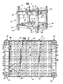
- FIG. 1 the Figures illustrate a knock-down display stand, generally 10, which comprises a plurality of shelves, each generally 12, molded as a unit of plastic and spaced vertically by tubular cardboard spacers, or post-segments 14. While the stand, illustrated in fragment in Fig. 1, is shown with only two shelves 12, it will be understood that multiple shelves may be employed, to provide a stand of any usable or desired height.
- the length of the tubular spacers, or post segments, 14 is selected so that goods stored upon any shelf 12 of the stand may easily be removed from the display stand by a shopper. If desirable, short spacers 14' may be provided below the lowermost shelf 12, to serve as feet for the display stand 10.
- the improved shelf 12 is a single, unitary, molded part, or product, that provides, as part thereof, rectangular, horizontal, product-support surface, or member, 16, as best seen in plan in Fig. 2.
- a continuous, peripheral, transverse flange means 18 formed integrally, with support member 16.
- the flange means 18 lies in a vertical plane transverse to horizontal support member 16 and projects both above and below the plane of horizontal support member 16.
- the portion of flange means 18 that projects above support member 16 serves, in part, as a side wall retainer, or rail, to confine and retain the goods supported on horizontal member 16.
- the entire flange means 18, located both above and below horizontal member 16, serves as a peripheral reinforcement of shelf member 16, providing reinforcement, or resistance, against bending or twisting of support member 16 and of the entire shelf 12.
- the shelf 12 is also provided with a tubular, corner post-receiving, means 20 adjacent each corner of the rectangular goods supporting member 16. These post-receiving means 20 are formed integrally with the support member 16 and with the flange means 18. As best seen in Figs. 3-6, each of the post-receiving means 20 is vertically elongated and projects transversely of the plane of the goods-supporting member 16, extending both above and below the plane of member 16.
- the positioning and location of the post-receiving means 20 relative to flange means 18 is such that a portion of the outer periphery of each post-receiving means 20 is tangent to the outer vertical surface of flange means 18, so that each post-receiving means 20 is located wholly outwardly of the inner surface 18a of flange means 18.
- the post-receiving means 20 are, as seen in Fig. 2, located wholly outwardly of and adjacent the short sides, or ends, 18', of the rectangular flange means 18, with a portion of the cylindrical wall of post-receiving means 20 being tangent to, and merging with, a segment of end portion 18' of flange means 18.
- An elongated reinforcing strip 22 is provided parallel to, and spaced outwardly of, each end 18' of flange means 18.
- Each reinforcing strip 22 is generally parallel to the end portion 18' and has its longitudinal ends terminating at the circular periphery of post-receiving means 20, at a distance horizontally spaced from end portion 18' that is greater than the radius of, but less than the diameter of, the tubular, post-receiving means 20.
- the vertical height of each reinforcing strip 22 corresponds substantially to the vertical height of flange means 18, so that the parallel flanges, or strips, 18' and 22 project substantially equal distances above and below the horizontal plane in which goods-supporting member 16 is located.
- the combination of walls 18', 22, and 24 provides a pair of downwardly opening channel-shaped sections at two opposite ends of the rectangular shaft 12, which together with the pair of tubular means 20 at the ends of each channel shaped section, provides substantial peripheral structural strength for shelf 12.
- the product-support member 16 is unobstructed on its upper, or support, surface, and is rectangular in shape, without invasion thereof from other structural portions of shelf 12.
- the underside of member 16 is further reinforced by two sets of spaced reinforcing ribs 28 and 30, arranged to intersect and provide a grid of orthogonal ribs which, at their ends, merge with pairs of parallel sides of the portion of flange 18 that is below support member 16.
- One set of reinforcing ribs 28 terminate at the short sides 18' of the flange 18, and the other set of reinforcing ribs 30 terminate at the long sides of flange 18.
- the ribs 28 and 30 are of substantially uniform height along their length, and may be of the same, or lesser, vertical height as the vertical extent of flange 18 that projects below support member 16.
- the underside of the channel shaped sections, provided in part by spaced walls 18' and 22, may be reinforced by ribs 28' that serve, in part and in effect, as extensions of ribs 28.
- said member 16 With the grid of orthogonal ribs 28 and 30 reinforcing the product-support member 16, said member 16 is provided with a plurality of apertures 32 therethrough to substantially reduce the total amount of plastic used in producing a shelf unit 12. This construction also avoids undesirable molding defects, such as ripple, in the surface of member 16, and provides an attractive design appearance.
- the apertures 32 may be of any selected outline, square, circular, or other geometrical form as desired. Preferably the apertures 32 are rectangular, as shown, and are arranged in a pattern that locates a plurality of apertures 32 spaced equally, and geometrically, from the vertical planes of the orthogonal reinforcing ribs 28 and 30.
- the support member 16 may be provided with a pair of wire- receiving apertures 17 adjacent each edge of support member as seen in Figs. 2 and 5, for receiving therein the ends of a wire-type frame that may serve as a mount for a sign or the like.
- Each corner post-receiving means 20 may be provided with post-receiving means, such as of the specific construction shown in detail in Figs. 2, 6 and 7.
- Each post-receiving means 20 includes a generally cylindrical sleeve 21 that is vertically oriented.
- the means 20 is formed to provide an upper cavity 40 and a lower cavity 42, both of generally cylindrical periphery defined by the inner surface of sleeve 21, which sections are separated by a transverse-wall 44 that is common to both said upper and lower cavities with wall 44 located axially between the ends of sleeve 21 and closer to the lower terminus of sleeve 21 than to the upper terminus of sleeve 21.
- Each upper cavity 40 has formed therein an upper stud 46, of star, or cross-shaped, cross-section as seen in Fig. 2, and of lesser vertical axial extent than the surrounding portion of sleeve 21.
- the maximum circumferential dimension of stud 46, defined by the stud's outer edges, is spaced concentrically inwardly of the inner wall of sleeve 21 to provide an annual groove, or recess, 48 adapted to receive, and grip therein, an end of a tubular cardboard post 14.
- the lower cavity 42 has therein a lower stud 50 concentric with sleeve 21, and with an axial length greater than the axial length of the portion of sleeve 21 that bounds lower cavity 42, so that stud 50 projects below the lower terminus of sleeve 21.
- the lower stud 50 is in the shape of an axially elongated tube 52 that is internally reinforced by a plurality of axially elongated ribs 54 that project from the inner wall of tube 52 radially inwardly, but do not engage each other, as seen in Fig. 7.
- the concentric outer sleeve 21 and inner lower stud 50 provide therebetween an annular recess 56 of a size to receive thereinto, in a snug fit, an upper end of a cardboard post 14.
- the size of tube 52 is selected to provide a snug and rigidifying fit with the interior of a tubular cardboard post 14. If desired, the tubular exterior of stud tube 52 may be provided with enlargements, or axial ridges, 58 which. provide for a tighter press-fit connection with the partially compressible wall of a tubular cardboard post 14.
- each stud 50 that project below the lower terminus of the surrounding sleeve 21 will serve as a support leg upon which the shelf is supported when the shelf is rested directly on the ground or on a floor, and serves to keep the lower edges of the sleeves 21 and of flange means 18 and of walls 22 spaced above the supporting surface and to substantially avoid wear or damage to those elements of the shelf.
- the axial length of that portion of stud 50, which projects below the lower edge of its surrounding sleeve 21 is selected to be greater than the axial spacing of the upper surface of stud 46 below the plane of the upper edge of sleeve 21.
- This relationship permits pairs of shelf members 12 to be stacked with the lower studs 50 of one shelf telescoped into the upper sleeves 21 of a second shelf, for purposes of space saving when effecting shipment to users, and without the upper and lower edges of the sleeves 21 and of the flange means 18 touching, thereby protecting against scuffing, abrasion, or damage of those parts which are visible in an assembled stand.
- a thin, circular, cardboard spacer may be introduced on top of each member 46 for purposes of preventing damage thereto when multiple shelf members 12 are stacked on each other for purposes of storage or shipment.
- the radial inner edges of the axially extending ribs 54 within tube 52 are designed to be located on the periphery of a circle that is of a size to releasably receive and grip, through a slip, or slight-press, fit the mounting stem, 60, of a caster 62 which is illustrated, as an alternative usage, by broken lines in Fig. 4.
- the use of casters at the four corners of a shelf, when the shelf is in its condition as shown in Figs. 3 and 4 as separate from a stand, will convert the shelf into a dolly.
Landscapes
- Assembled Shelves (AREA)
Claims (10)
Applications Claiming Priority (2)
| Application Number | Priority Date | Filing Date | Title |
|---|---|---|---|
| US06/407,460 US4467927A (en) | 1982-08-12 | 1982-08-12 | Molded tray for display stands |
| US407460 | 2003-04-07 |
Publications (3)
| Publication Number | Publication Date |
|---|---|
| EP0101647A2 EP0101647A2 (de) | 1984-02-29 |
| EP0101647A3 EP0101647A3 (en) | 1984-03-28 |
| EP0101647B1 true EP0101647B1 (de) | 1987-12-02 |
Family
ID=23612197
Family Applications (1)
| Application Number | Title | Priority Date | Filing Date |
|---|---|---|---|
| EP83304666A Expired EP0101647B1 (de) | 1982-08-12 | 1983-08-12 | Geformtes Auslagetablett |
Country Status (3)
| Country | Link |
|---|---|
| US (1) | US4467927A (de) |
| EP (1) | EP0101647B1 (de) |
| DE (1) | DE3374755D1 (de) |
Families Citing this family (142)
| Publication number | Priority date | Publication date | Assignee | Title |
|---|---|---|---|---|
| US4574709A (en) * | 1983-12-05 | 1986-03-11 | The Mead Corporation | Shelf element and support therefor |
| DE8403538U1 (de) * | 1984-02-07 | 1984-07-12 | Display-Design GmbH für moderne Verkaufsförderungsmittel und Raumaussstattung, 6233 Kelkheim | Etagenturm zur warenausstellung |
| US4815394A (en) * | 1984-05-17 | 1989-03-28 | Amco Corporation | Adjustable rack of shelves |
| USD288160S (en) | 1984-07-25 | 1987-02-10 | Plug-In Storage Systems, Inc. | Storage shelf |
| US4579233A (en) * | 1984-08-09 | 1986-04-01 | James Hepp | Adjustable knockdown tray assembly |
| DE3507158A1 (de) * | 1985-03-01 | 1986-09-04 | Rudolf Dipl.-Wirtsch.-Ing. 3548 Arolsen Wilke | Plattenhalter |
| GB2179246A (en) * | 1985-08-27 | 1987-03-04 | James Thomas Nicholls | Apparatus for storing tools |
| US4620637A (en) * | 1985-09-09 | 1986-11-04 | Masashi Karashima | Trolley |
| US4673092A (en) * | 1985-09-30 | 1987-06-16 | Lockwood Manufacturing Company | Multi-level rack assembly |
| US4706824A (en) * | 1986-03-25 | 1987-11-17 | Marlboro Marketing, Inc. | Variable sized free standing promotional display |
| US4706576A (en) * | 1986-03-27 | 1987-11-17 | Barry James | Interlocking plastic shelving system |
| US4852501A (en) * | 1986-05-16 | 1989-08-01 | Amco Corporation | Adjustable rack of shelves |
| USD308778S (en) | 1987-02-26 | 1990-06-26 | Gambello Vincent J | Stackable display rack |
| US4763796A (en) * | 1987-03-20 | 1988-08-16 | Paul Flum Ideas, Inc. | Gravity feed display systems and conversion means for obtaining same |
| US4843975A (en) * | 1987-07-22 | 1989-07-04 | Intermetro Industries Corporation | Storage shelf |
| US4964350A (en) * | 1987-07-24 | 1990-10-23 | Intermetro Industries Corporation | Plastic frame system having a triangular support post |
| DE8717550U1 (de) * | 1987-08-10 | 1989-02-02 | Display-Design GmbH für moderne Verkaufsförderungsmittel und Raumausstattung, 6233 Kelkheim | Etagenturm |
| US4930643A (en) * | 1987-11-02 | 1990-06-05 | Paul Flum Ideas, Inc. | Display unit with modular capability |
| US4836393A (en) * | 1988-08-11 | 1989-06-06 | Robert Maye | Modular display stand |
| USD324787S (en) | 1989-05-16 | 1992-03-24 | Tucker Housewares | Stackable shoe rack |
| USD333059S (en) | 1989-05-19 | 1993-02-09 | Intermetro Industries Corporation | Shelf |
| US4940150A (en) * | 1989-07-14 | 1990-07-10 | Tolco Corporation | Modular storage rack |
| US4989519A (en) * | 1989-07-25 | 1991-02-05 | Intermetro Industries Corporation | Shelving system having two sets of locking tapers |
| US4953719A (en) * | 1989-10-03 | 1990-09-04 | The Mead Corporation | Article organizer display unit |
| US4976360A (en) * | 1990-01-12 | 1990-12-11 | Rtc Industries, Inc. | Merchandise display stand |
| US4982849A (en) * | 1990-03-05 | 1991-01-08 | Paul Flum Ideas, Inc. | Adapter means for converting a horizontally arranged shelf member in a modular display unit to an angular orientation |
| NL9001100A (nl) * | 1990-05-08 | 1991-12-02 | Bloembollenkwekerij En Handel | Stapelbare doos. |
| US5188246A (en) * | 1991-05-29 | 1993-02-23 | International Visual Corporation | Shelf |
| US5097969A (en) * | 1991-05-29 | 1992-03-24 | International Visual Corporation | Shelf |
| US5238128A (en) * | 1991-06-24 | 1993-08-24 | The Mead Corporation | Knockdown display stand |
| USD338792S (en) | 1991-08-26 | 1993-08-31 | Amco Corporation | Shelf |
| US5291838A (en) * | 1991-10-10 | 1994-03-08 | Tandem Computers Incorporated | Packaging system |
| GB9218251D0 (en) * | 1992-08-27 | 1992-10-14 | Morrish Peter G A | Stackable trays |
| USD339704S (en) | 1992-10-01 | 1993-09-28 | Intermetro Industries Corporation | Shelf |
| US5577344A (en) * | 1993-02-05 | 1996-11-26 | Zaremba; George J. | Party riser |
| US5400719A (en) * | 1993-10-04 | 1995-03-28 | Selfix, Inc. | Modular assembly and components therefor |
| US5579702A (en) * | 1994-03-16 | 1996-12-03 | Structural Plastics Corporation | Shelving construction |
| US5709158A (en) * | 1994-03-31 | 1998-01-20 | Contico International Company | Shelf structure |
| US5505142A (en) * | 1994-05-31 | 1996-04-09 | Fink; Virginia W. | Lightweight stacking table with folding legs |
| US5918751A (en) * | 1994-09-22 | 1999-07-06 | Tulip Corporation | Display tray |
| USD398152S (en) | 1996-06-28 | 1998-09-15 | Tulip Corporation | Beverage container case |
| USD371239S (en) | 1994-11-21 | 1996-07-02 | Tulip Corporation | Side element of a beverage container case |
| USD383339S (en) * | 1995-11-10 | 1997-09-09 | Grosfillex Sarl | Reversible shelf |
| US6123206A (en) * | 1996-01-16 | 2000-09-26 | Zaremba; George Julian | Removable display attachment with wedgelike retainers for vertical rigid cylindrical supports |
| US5683004A (en) * | 1996-05-22 | 1997-11-04 | Structural Plastics Corporation | Stackable and unstackable support construction |
| US5971174A (en) * | 1997-05-12 | 1999-10-26 | Strock; Douglas J. | Stackable modular display rack |
| US6079339A (en) * | 1998-05-26 | 2000-06-27 | Rubbermaid Incorporated | Shelving system |
| USD406713S (en) * | 1998-05-26 | 1999-03-16 | Rubbermaid Incorporated | Shelf |
| US7028957B1 (en) | 1998-10-15 | 2006-04-18 | John Larson | Easily assembled and disassembled tables |
| US6401946B1 (en) * | 2000-05-10 | 2002-06-11 | Subhas Chandra Chalasani | Composite battery stand with integral spill containment |
| US6520356B2 (en) * | 2000-06-28 | 2003-02-18 | Paul Flum Ideas, Inc. | Double socket product merchandising display unit |
| US6820757B2 (en) | 2001-01-12 | 2004-11-23 | Rubbermaid Incorporated | Beam structures for shelving apparatus |
| US6460709B1 (en) * | 2001-01-23 | 2002-10-08 | Vertex International | Storage device |
| US7931156B2 (en) | 2001-05-17 | 2011-04-26 | Rtc Industries, Inc. | Product management display system with retaining wall |
| US8096427B2 (en) | 2002-05-17 | 2012-01-17 | Rtc Industries, Inc. | Product management display system |
| CA2447076C (en) * | 2001-05-17 | 2007-08-21 | Rtc Industries, Inc. | Product management display system |
| US7152536B2 (en) * | 2004-02-03 | 2006-12-26 | Rtc Industries, Inc. | Product management display system |
| US8627965B2 (en) | 2001-05-17 | 2014-01-14 | Rtc Industries, Inc. | Multi-component display and merchandise systems |
| WO2003065849A1 (en) * | 2002-02-07 | 2003-08-14 | Rubbermaid Incorporated | Basket type free-standing shelving system |
| USD477933S1 (en) | 2002-05-02 | 2003-08-05 | George W. Wood | Locker shelf assembly with slidable drawer |
| US6892993B2 (en) * | 2003-08-19 | 2005-05-17 | Lanxess Corporation | Load bearing article |
| US20050040123A1 (en) * | 2003-08-22 | 2005-02-24 | Ala Ali | Inventory control system |
| DE10347408A1 (de) * | 2003-10-11 | 2005-06-02 | Blanco Gmbh + Co Kg | Transportwagen |
| US7661545B2 (en) * | 2004-02-03 | 2010-02-16 | Rtc Industries, Inc. | Product securement and management system |
| US7451881B2 (en) | 2004-02-03 | 2008-11-18 | Rtc Industries, Inc. | Product securement and management system |
| US7792711B2 (en) | 2004-02-03 | 2010-09-07 | Rtc Industries, Inc. | System for inventory management |
| US9375100B2 (en) | 2004-02-03 | 2016-06-28 | Rtc Industries, Inc. | Product securement and management system |
| US8047385B2 (en) | 2004-02-03 | 2011-11-01 | Rtc Industries, Inc. | Product securement and management system |
| US7621409B2 (en) * | 2004-02-03 | 2009-11-24 | Rtc Industries, Inc. | Product securement and management system |
| US7150365B2 (en) * | 2004-02-03 | 2006-12-19 | Rtc Industries, Inc. | Product securement and management system |
| US9818148B2 (en) | 2013-03-05 | 2017-11-14 | Rtc Industries, Inc. | In-store item alert architecture |
| US9706857B2 (en) | 2004-02-03 | 2017-07-18 | Rtc Industries, Inc. | Product securement and management system |
| US9898712B2 (en) | 2004-02-03 | 2018-02-20 | Rtc Industries, Inc. | Continuous display shelf edge label device |
| US8235222B2 (en) * | 2004-02-03 | 2012-08-07 | Rtc Industries, Inc. | Product securement and management system |
| US11375826B2 (en) * | 2004-02-03 | 2022-07-05 | Rtc Industries, Inc. | Product securement and management system |
| US7404494B2 (en) * | 2004-02-03 | 2008-07-29 | Rtc Industries, Inc. | Kinetic inertial delivery system |
| US8938396B2 (en) | 2004-02-03 | 2015-01-20 | Rtc Industries, Inc. | System for inventory management |
| US8113601B2 (en) | 2004-02-03 | 2012-02-14 | Rtc Industries, Inc. | Product securement and management system |
| US10339495B2 (en) | 2004-02-03 | 2019-07-02 | Rtc Industries, Inc. | System for inventory management |
| US7828158B2 (en) | 2005-07-14 | 2010-11-09 | Displays Plus, Inc. | Merchandise dispensing apparatus providing theft deterrence |
| DE202005013047U1 (de) * | 2005-08-18 | 2005-11-03 | Korte, Hermann, Dipl.-Ing. | Lagerungsvorrichtung |
| US8453850B2 (en) | 2005-09-12 | 2013-06-04 | Rtc Industries, Inc. | Product management display system with trackless pusher mechanism |
| US10285510B2 (en) | 2005-09-12 | 2019-05-14 | Rtc Industries, Inc. | Product management display system |
| US9265358B2 (en) | 2005-09-12 | 2016-02-23 | RTC Industries, Incorporated | Product management display system |
| US9265362B2 (en) | 2005-09-12 | 2016-02-23 | RTC Industries, Incorporated | Product management display system |
| US9173504B2 (en) | 2005-09-12 | 2015-11-03 | Rtc Industries, Inc. | Product management display system |
| US10952546B2 (en) | 2005-09-12 | 2021-03-23 | Rtc Industries, Inc. | Product management display system with trackless pusher mechanism |
| US8863963B2 (en) | 2005-09-12 | 2014-10-21 | Rtc Industries, Inc. | Product management display system with trackless pusher mechanism |
| US11344138B2 (en) | 2005-09-12 | 2022-05-31 | Rtc Industries, Inc. | Product management display system |
| US9750354B2 (en) | 2005-09-12 | 2017-09-05 | Rtc Industries, Inc. | Product management display system |
| US9259102B2 (en) | 2005-09-12 | 2016-02-16 | RTC Industries, Incorporated | Product management display system with trackless pusher mechanism |
| US9486088B2 (en) | 2005-09-12 | 2016-11-08 | Rtc Industries, Inc. | Product management display system |
| US8739984B2 (en) | 2005-09-12 | 2014-06-03 | Rtc Industries, Inc. | Product management display system with trackless pusher mechanism |
| US8312999B2 (en) | 2005-09-12 | 2012-11-20 | Rtc Industries, Inc. | Product management display system with trackless pusher mechanism |
| US11583109B2 (en) | 2005-09-12 | 2023-02-21 | Rtc Industries, Inc. | Product management display system with trackless pusher mechanism |
| US7823734B2 (en) | 2005-09-12 | 2010-11-02 | Rtc Industries, Inc. | Product management display system with trackless pusher mechanism |
| US11259652B2 (en) | 2005-09-12 | 2022-03-01 | Rtc Industries, Inc. | Product management display system |
| US8978904B2 (en) | 2005-09-12 | 2015-03-17 | Rtc Industries, Inc. | Product management display system with trackless pusher mechanism |
| US9232864B2 (en) | 2005-09-12 | 2016-01-12 | RTC Industries, Incorporated | Product management display system with trackless pusher mechanism |
| US9060624B2 (en) | 2005-09-12 | 2015-06-23 | Rtc Industries, Inc. | Product management display system with rail mounting clip |
| US9138075B2 (en) | 2005-09-12 | 2015-09-22 | Rtc Industries, Inc. | Product management display system |
| US8967394B2 (en) | 2005-09-12 | 2015-03-03 | Rtc Industries, Inc. | Product management display system with trackless pusher mechanism |
| US7628282B2 (en) * | 2005-10-25 | 2009-12-08 | Rtc Industries, Inc. | Product management display system |
| US7497342B2 (en) * | 2005-10-25 | 2009-03-03 | Rtc Industries, Inc. | Product management display system |
| WO2008051996A2 (en) | 2006-10-23 | 2008-05-02 | Rtc Industries, Inc. | Merchandising system with flippable column |
| US7779595B2 (en) * | 2006-10-25 | 2010-08-24 | Lrm Industries International, Inc. | Molded panel and panel assembly |
| US20090224125A1 (en) * | 2007-09-18 | 2009-09-10 | Structural Plastics, Inc. | Couplers for stackable platforms |
| US20090071380A1 (en) * | 2007-09-19 | 2009-03-19 | Sheng-Jui Chen | Board for pasturage |
| US8091314B2 (en) * | 2008-01-21 | 2012-01-10 | Lrm Industries International, Inc. | Load bearing assembly |
| US20110036798A1 (en) * | 2009-08-17 | 2011-02-17 | Po-Ju Chen | Building Unit for Modular Rack |
| US8191489B1 (en) * | 2010-05-06 | 2012-06-05 | Smith Gene A | Collapsible transport, storage and display table |
| AU2011200862A1 (en) * | 2010-08-06 | 2012-02-23 | Wasson-Mantova Pty Ltd | A shelf |
| US8657113B1 (en) * | 2013-01-31 | 2014-02-25 | Kenneth G. McCauley | Tool storage and bolt organizer device |
| US10357118B2 (en) | 2013-03-05 | 2019-07-23 | Rtc Industries, Inc. | Systems and methods for merchandizing electronic displays |
| US9538846B2 (en) | 2013-03-15 | 2017-01-10 | Continental Commercial Products, Llc | Shelving system and shelf for same |
| US9364084B2 (en) * | 2014-06-04 | 2016-06-14 | Vishal Durgadutt Rege | Two-tiered boot tray with umbrella drip tray stand |
| US9717330B2 (en) * | 2014-06-05 | 2017-08-01 | Creative Plastic Concepts, Llc | Shelving with molded end caps |
| US11109692B2 (en) | 2014-11-12 | 2021-09-07 | Rtc Industries, Inc. | Systems and methods for merchandizing electronic displays |
| US11182738B2 (en) | 2014-11-12 | 2021-11-23 | Rtc Industries, Inc. | System for inventory management |
| USD775883S1 (en) * | 2014-12-23 | 2017-01-10 | New Dimensions Research Corporation | Shelf for a display unit |
| US20160214763A1 (en) * | 2015-01-28 | 2016-07-28 | Rondi Industries Inc. | Stackable interlocking tray system |
| USD804848S1 (en) | 2015-01-28 | 2017-12-12 | Rondi Industries Inc. | Boot tray |
| US9955802B2 (en) | 2015-04-08 | 2018-05-01 | Fasteners For Retail, Inc. | Divider with selectively securable track assembly |
| USD759999S1 (en) | 2015-06-04 | 2016-06-28 | Vishal Durgadutt Rege | Two tiered boot tray |
| US11666159B2 (en) * | 2015-06-24 | 2023-06-06 | Mbm Spa | Configurable and dismantlable display case system and method of assembly |
| NL2015372B1 (en) * | 2015-08-31 | 2017-05-24 | Container Centralen As | Trolley for carrying goods. |
| EP3402371B1 (de) | 2016-01-13 | 2020-03-04 | RTC Industries, Inc. | Warenauslagesystem mit einer spreizschutzvorrichtung |
| USD820003S1 (en) * | 2017-04-10 | 2018-06-12 | Grey Man Tactical Llc | MOLLE support panel |
| CL2017001656A1 (es) * | 2017-06-02 | 2018-03-09 | Wenco Sa | Caja plástica de menos de 450 gr. para la exportación de productos hortofrutícolas |
| CN113679209A (zh) | 2017-06-16 | 2021-11-23 | Rtc工业股份有限公司 | 具有无轨道推动器机构的产品管理显示系统 |
| CN107971991A (zh) * | 2017-12-28 | 2018-05-01 | 重庆臻展热处理有限公司 | 一种热处理管件安置架 |
| IL257349A (en) * | 2018-02-04 | 2018-03-29 | Keter Plastic Ltd | A compact firefighting system |
| US11369215B2 (en) | 2018-12-17 | 2022-06-28 | Fasteners For Retail, Inc. | Retail shelving system |
| EP3922140A3 (de) | 2020-04-23 | 2022-02-16 | Fasteners for Retail, Inc. | Warenregalsystem für den einzelhandel |
| US12053106B2 (en) | 2020-05-28 | 2024-08-06 | Fasteners For Retail, Inc. | Retail merchandise shelving system and deck panels for same |
| USD1005752S1 (en) * | 2021-06-28 | 2023-11-28 | Suncast Technologies, Llc | Blow molded shelf |
| USD1100735S1 (en) * | 2022-10-11 | 2025-11-04 | CGIP, Inc. | Shelf for plant cultivation |
| US11925154B1 (en) * | 2022-10-11 | 2024-03-12 | CGIP, Inc. | System for plant cultivation |
| USD1100536S1 (en) * | 2022-10-11 | 2025-11-04 | CGIP, Inc. | Shelf for plant cultivation |
| USD1106704S1 (en) * | 2022-10-11 | 2025-12-23 | CGIP, Inc. | Shelf for plant cultivation |
| USD1100535S1 (en) * | 2022-10-11 | 2025-11-04 | CGIP, Inc. | Shelf for plant cultivation |
| USD1087940S1 (en) * | 2024-01-11 | 2025-08-12 | John Charles Licitra | Cabinet platform |
Family Cites Families (12)
| Publication number | Priority date | Publication date | Assignee | Title |
|---|---|---|---|---|
| CA759799A (en) * | 1967-05-30 | Svilokos Eli | Footwear rack | |
| US3170415A (en) * | 1963-05-17 | 1965-02-23 | Svilokos Eli | Arctic stand |
| CH505590A (it) * | 1970-01-13 | 1971-04-15 | Carrara & Matta Spa | Mobiletto montato su rotelle |
| US3664274A (en) * | 1970-11-12 | 1972-05-23 | Southern Cross Ind Inc | Adjustable merchandise support with spaced, molded shelves |
| US3749343A (en) * | 1971-10-15 | 1973-07-31 | H Marschak | Means for connecting adjacent railings to a post to form a support for forming a bookcase, shelving, or the like |
| DE2153603C3 (de) * | 1971-10-27 | 1981-02-26 | Franz Josef 6233 Kelkheim Lang | Etagenturm zur Warenausstellung |
| US3777673A (en) * | 1972-03-22 | 1973-12-11 | Century Products Inc | Security top or guard for infant{40 s dressing table or the like |
| US3927769A (en) * | 1974-04-29 | 1975-12-23 | Metropolitan Wire Corp | Shelf structure |
| GB1485260A (en) * | 1976-04-27 | 1977-09-08 | Star Ind Co Ltd | Table |
| US4099472A (en) * | 1977-05-31 | 1978-07-11 | Kellogg Harlan F | Free standing shelving system |
| DE3006377C2 (de) * | 1980-02-20 | 1983-11-24 | Franz Josef 6233 Kelkheim Lang | Etagenturm |
| US4428487A (en) * | 1982-04-15 | 1984-01-31 | James Hepp | Dual side wall locking attachment for trays to vertical legs in sectional display rack |
-
1982
- 1982-08-12 US US06/407,460 patent/US4467927A/en not_active Expired - Fee Related
-
1983
- 1983-08-12 DE DE8383304666T patent/DE3374755D1/de not_active Expired
- 1983-08-12 EP EP83304666A patent/EP0101647B1/de not_active Expired
Also Published As
| Publication number | Publication date |
|---|---|
| EP0101647A2 (de) | 1984-02-29 |
| US4467927A (en) | 1984-08-28 |
| DE3374755D1 (en) | 1988-01-14 |
| EP0101647A3 (en) | 1984-03-28 |
Similar Documents
| Publication | Publication Date | Title |
|---|---|---|
| EP0101647B1 (de) | Geformtes Auslagetablett | |
| US4257333A (en) | Shelving structure adapted for quick assembly and adjustment | |
| US4588096A (en) | Knock-down tray rack | |
| EP0539957B1 (de) | Modulares Regal mit Schnellwechselsystem | |
| US4004819A (en) | Mobile truck provided with improved removable racks for pans, trays and the like | |
| US6015052A (en) | Modular shelving system | |
| US5289936A (en) | Plastic basket | |
| USRE42988E1 (en) | Wire chafing stand | |
| US4763799A (en) | Modular utility cart including improved structures for securing intermediate and top shelves to corner posts | |
| US4501369A (en) | Merchandise display means | |
| US5452811A (en) | Stackable partitioned shipping container | |
| US3233251A (en) | Pool structure | |
| US3685664A (en) | Turnable display device | |
| US7059484B1 (en) | Adjustable modular shelf | |
| US5605102A (en) | Hand cart platform | |
| US5485934A (en) | Merchandise display assembly | |
| US3777895A (en) | Display stand for yard goods | |
| CA2886217C (en) | Storage or transportation cart for retail shelving | |
| US5996948A (en) | Wire chafing stand | |
| US5499726A (en) | Multiple-height modular display pedestal for displaying merchandise | |
| US20050126448A1 (en) | Modular pallet | |
| CA2420123C (en) | Frameless display fixture | |
| US4121710A (en) | Display bin | |
| US4052081A (en) | Bussing cart | |
| US3104627A (en) | Steel shelving construction |
Legal Events
| Date | Code | Title | Description |
|---|---|---|---|
| PUAI | Public reference made under article 153(3) epc to a published international application that has entered the european phase |
Free format text: ORIGINAL CODE: 0009012 |
|
| PUAL | Search report despatched |
Free format text: ORIGINAL CODE: 0009013 |
|
| AK | Designated contracting states |
Designated state(s): DE FR GB |
|
| AK | Designated contracting states |
Designated state(s): DE FR GB |
|
| 17P | Request for examination filed |
Effective date: 19840924 |
|
| RAP1 | Party data changed (applicant data changed or rights of an application transferred) |
Owner name: NATHAN, WALTER |
|
| GRAA | (expected) grant |
Free format text: ORIGINAL CODE: 0009210 |
|
| AK | Designated contracting states |
Kind code of ref document: B1 Designated state(s): DE FR GB |
|
| REF | Corresponds to: |
Ref document number: 3374755 Country of ref document: DE Date of ref document: 19880114 |
|
| ET | Fr: translation filed | ||
| PLBE | No opposition filed within time limit |
Free format text: ORIGINAL CODE: 0009261 |
|
| STAA | Information on the status of an ep patent application or granted ep patent |
Free format text: STATUS: NO OPPOSITION FILED WITHIN TIME LIMIT |
|
| 26N | No opposition filed | ||
| PGFP | Annual fee paid to national office [announced via postgrant information from national office to epo] |
Ref country code: GB Payment date: 19950801 Year of fee payment: 13 |
|
| PGFP | Annual fee paid to national office [announced via postgrant information from national office to epo] |
Ref country code: FR Payment date: 19950809 Year of fee payment: 13 Ref country code: DE Payment date: 19950809 Year of fee payment: 13 |
|
| PG25 | Lapsed in a contracting state [announced via postgrant information from national office to epo] |
Ref country code: GB Effective date: 19960812 |
|
| GBPC | Gb: european patent ceased through non-payment of renewal fee |
Effective date: 19960812 |
|
| PG25 | Lapsed in a contracting state [announced via postgrant information from national office to epo] |
Ref country code: FR Effective date: 19970430 |
|
| PG25 | Lapsed in a contracting state [announced via postgrant information from national office to epo] |
Ref country code: DE Effective date: 19970501 |
|
| REG | Reference to a national code |
Ref country code: FR Ref legal event code: ST |