EP0101814B1 - Automatisch arbeitende Vorrichtung zur Herstellung von Zeichen - Google Patents
Automatisch arbeitende Vorrichtung zur Herstellung von Zeichen Download PDFInfo
- Publication number
- EP0101814B1 EP0101814B1 EP83106132A EP83106132A EP0101814B1 EP 0101814 B1 EP0101814 B1 EP 0101814B1 EP 83106132 A EP83106132 A EP 83106132A EP 83106132 A EP83106132 A EP 83106132A EP 0101814 B1 EP0101814 B1 EP 0101814B1
- Authority
- EP
- European Patent Office
- Prior art keywords
- tool
- cutting
- plotting
- support
- sheet material
- Prior art date
- Legal status (The legal status is an assumption and is not a legal conclusion. Google has not performed a legal analysis and makes no representation as to the accuracy of the status listed.)
- Expired - Lifetime
Links
Images

Classifications
-
- B—PERFORMING OPERATIONS; TRANSPORTING
- B26—HAND CUTTING TOOLS; CUTTING; SEVERING
- B26D—CUTTING; DETAILS COMMON TO MACHINES FOR PERFORATING, PUNCHING, CUTTING-OUT, STAMPING-OUT OR SEVERING
- B26D5/00—Arrangements for operating and controlling machines or devices for cutting, cutting-out, stamping-out, punching, perforating, or severing by means other than cutting
- B26D5/02—Means for moving the cutting member into its operative position for cutting
-
- B—PERFORMING OPERATIONS; TRANSPORTING
- B26—HAND CUTTING TOOLS; CUTTING; SEVERING
- B26F—PERFORATING; PUNCHING; CUTTING-OUT; STAMPING-OUT; SEVERING BY MEANS OTHER THAN CUTTING
- B26F1/00—Perforating; Punching; Cutting-out; Stamping-out; Apparatus therefor
- B26F1/02—Perforating by punching, e.g. with relatively-reciprocating punch and bed
- B26F1/06—Perforating by punching, e.g. with relatively-reciprocating punch and bed with punching tools moving with the work
- B26F1/10—Roller type punches
-
- B—PERFORMING OPERATIONS; TRANSPORTING
- B26—HAND CUTTING TOOLS; CUTTING; SEVERING
- B26F—PERFORATING; PUNCHING; CUTTING-OUT; STAMPING-OUT; SEVERING BY MEANS OTHER THAN CUTTING
- B26F1/00—Perforating; Punching; Cutting-out; Stamping-out; Apparatus therefor
- B26F1/24—Perforating by needles or pins
-
- B—PERFORMING OPERATIONS; TRANSPORTING
- B26—HAND CUTTING TOOLS; CUTTING; SEVERING
- B26F—PERFORATING; PUNCHING; CUTTING-OUT; STAMPING-OUT; SEVERING BY MEANS OTHER THAN CUTTING
- B26F1/00—Perforating; Punching; Cutting-out; Stamping-out; Apparatus therefor
- B26F1/38—Cutting-out; Stamping-out
- B26F1/3806—Cutting-out; Stamping-out wherein relative movements of tool head and work during cutting have a component tangential to the work surface
-
- B—PERFORMING OPERATIONS; TRANSPORTING
- B43—WRITING OR DRAWING IMPLEMENTS; BUREAU ACCESSORIES
- B43L—ARTICLES FOR WRITING OR DRAWING UPON; WRITING OR DRAWING AIDS; ACCESSORIES FOR WRITING OR DRAWING
- B43L13/00—Drawing instruments, or writing or drawing appliances or accessories not otherwise provided for
- B43L13/02—Draughting machines or drawing devices for keeping parallelism
- B43L13/022—Draughting machines or drawing devices for keeping parallelism automatic
- B43L13/026—Draughting machines or drawing devices for keeping parallelism automatic for writing characters or symbols
-
- G—PHYSICS
- G06—COMPUTING OR CALCULATING; COUNTING
- G06K—GRAPHICAL DATA READING; PRESENTATION OF DATA; RECORD CARRIERS; HANDLING RECORD CARRIERS
- G06K15/00—Arrangements for producing a permanent visual presentation of the output data, e.g. computer output printers
- G06K15/22—Arrangements for producing a permanent visual presentation of the output data, e.g. computer output printers using plotters
-
- B—PERFORMING OPERATIONS; TRANSPORTING
- B26—HAND CUTTING TOOLS; CUTTING; SEVERING
- B26D—CUTTING; DETAILS COMMON TO MACHINES FOR PERFORATING, PUNCHING, CUTTING-OUT, STAMPING-OUT OR SEVERING
- B26D7/00—Details of apparatus for cutting, cutting-out, stamping-out, punching, perforating, or severing by means other than cutting
- B26D7/26—Means for mounting or adjusting the cutting member; Means for adjusting the stroke of the cutting member
- B26D2007/2678—Means for mounting or adjusting the cutting member; Means for adjusting the stroke of the cutting member for cutting pens mounting in a cutting plotter
-
- Y—GENERAL TAGGING OF NEW TECHNOLOGICAL DEVELOPMENTS; GENERAL TAGGING OF CROSS-SECTIONAL TECHNOLOGIES SPANNING OVER SEVERAL SECTIONS OF THE IPC; TECHNICAL SUBJECTS COVERED BY FORMER USPC CROSS-REFERENCE ART COLLECTIONS [XRACs] AND DIGESTS
- Y10—TECHNICAL SUBJECTS COVERED BY FORMER USPC
- Y10T—TECHNICAL SUBJECTS COVERED BY FORMER US CLASSIFICATION
- Y10T83/00—Cutting
- Y10T83/02—Other than completely through work thickness
- Y10T83/0333—Scoring
-
- Y—GENERAL TAGGING OF NEW TECHNOLOGICAL DEVELOPMENTS; GENERAL TAGGING OF CROSS-SECTIONAL TECHNOLOGIES SPANNING OVER SEVERAL SECTIONS OF THE IPC; TECHNICAL SUBJECTS COVERED BY FORMER USPC CROSS-REFERENCE ART COLLECTIONS [XRACs] AND DIGESTS
- Y10—TECHNICAL SUBJECTS COVERED BY FORMER USPC
- Y10T—TECHNICAL SUBJECTS COVERED BY FORMER US CLASSIFICATION
- Y10T83/00—Cutting
- Y10T83/02—Other than completely through work thickness
- Y10T83/0333—Scoring
- Y10T83/0385—Rotary scoring blade
-
- Y—GENERAL TAGGING OF NEW TECHNOLOGICAL DEVELOPMENTS; GENERAL TAGGING OF CROSS-SECTIONAL TECHNOLOGIES SPANNING OVER SEVERAL SECTIONS OF THE IPC; TECHNICAL SUBJECTS COVERED BY FORMER USPC CROSS-REFERENCE ART COLLECTIONS [XRACs] AND DIGESTS
- Y10—TECHNICAL SUBJECTS COVERED BY FORMER USPC
- Y10T—TECHNICAL SUBJECTS COVERED BY FORMER US CLASSIFICATION
- Y10T83/00—Cutting
- Y10T83/283—With means to control or modify temperature of apparatus or work
- Y10T83/293—Of tool
Definitions
- the present invention relates to an apparatus for plotting an cutting large scale text in sheet materials for signs and the like including: a material support for holding and moving the sheet material back and forth in one coordinate direction during plotting and cutting operations; a tool carriage mounted adjacent the support and movable relative to the material during cutting and plotting operation; interchangable cutting and plotting tools; a tool support movable on the tool carriage between an elevated and lowered position relative to the support and having a tool mount accepting the interchangeable cutting and plotting tools one at a time for movement with the support between the elevated and lowered positions and into and out of working engagement with the sheet material on the support; a lift motor connected with the tool support for moving .the support and the tool between the elevated and lowered positions to engage and disengage the sheet material; a drive motor connected with the tool carriage and the support for moving the tool and the sheet material on the support relative to one another.
- the invention starts from an engraving machine as described in "The Engraver's Journal", July/ August 1980, pp 12, 14, 44-49. With the known machine, it is not possible to work sheet material having a great length compared with the machine.
- U.S. Patent 3,826,167 describes a more developed sign forming apparatus utilizing heated cutting dies.
- the text of a sign is cut in a thermoplastic sign material adhesively secured to a paper release liner.
- a strip of the material and liner is fed past a cutting station at which a heated die is pressed through the thermoplastic material to the liner in order to cut a character such as letter or numberforming part of the sign text.
- a character such as letter or numberforming part of the sign text.
- a full line of text is prepared on the liner with each character and word spaced exactly as desired in the finished sign.
- the spacing of individual letters is accomplished by means of suitable indicia on the dies and such spacing may be varied if desired for aesthetic or other reasons.
- the cut characters are limited to the specific configuration of the dies, and changes in height, slant or width of the characters require a totally new set of dies.
- the dies must be individually snatched from a heating station, brought into cutting engagement with the thermoplastic material, and then removed to a cooling station so that the die can thereafter be manually handled.
- U.S. Patent 3,465,627 discloses another type of hot cutting die for cutting an adhesively-backed thermoplastic film releasably secured to a release liner.
- the die shown in this patent is constructed of a material suitable for heating above the melting temperature of the film and has a coated cutting surface configured to cut the desired character or pattern in the film.
- the present invention resides in an apparatus for generating sign text on sheet material with the same spacing and positioning of text characters as desired in the finished sign.
- the sheet material may be a thermoplastic material adhesively secured to a release liner for cutting text and transferring the text from the liner to a signboard or other object.
- the invention is characterized in that the material support is comprised by a rotatable roller having an axis of rotation extending in one direction and a cylindrical, work-engaging surface circumscribing the roller axis and over which a flexible strip of sheet material is fed during plotting or cutting operations to prepare signs of extended length; a second drive motor for moving the flexible strip of sheet material over the cylindrical work-engaging surface of the rotatable roller and relative to the tool support and interchangeable cutting and plotting tools; the tool carriage is movable relative to the feed roller in a direction parallel to the axis of rotation of the roller with one of the cutting and plotting tools mounted in the tool support and translating over the cylindrical surface of the roller and controls are connected with the drive motor and the lift motor for controlling thetool and sheet material movements during cutting and plotting operations.
- the apparatus includes support means having a support surface for holding the sheet material and the underlying liner during a cutting operation.
- Cutting means having a cutting tool is suspended over the support surface holding the sheet material for cutting through the sheet material to the liner without cutting through the liner.
- the cutting tool may be a heated stylus or blade that rests on the material under a light pressure sufficient to penetrate the thermoplastic but not the liner.
- the liner thus holds the cut text characters in the same positions and spacing as cut which preferably corresponds to the positions and spacing in the finished sign.
- a plotting tool may be substituted for the cutting tool to plot the text for proofing or layout purposes.
- a motor means moves the sheet material with the liner and the cutting or plotting tool relative to one another as the tool generates each sign text character on the material.
- the apparatus produces large scale text on sheet material by means of a cutting tool which is guided relative to the material.
- the sheet material is supported for movement in one coordinate direction relative to the tool by a feed roller, and the cutting tool is supported for movement in an orthogonal coordinate direction parallel to the roller.
- Several cutting tools are employed and one of the tools is heated to penetrate through a vinyl sign material that is releasably secured by a pressure sensitive adhesive to a paper release liner.
- a plotting tool can also be substituted for the cutting tool to plot the sign on plain paper.
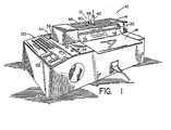
- Fig. 1 illustrates a sign generating apparatus, generally designated 10, for plotting or cutting a single line of text on a sheet material such as plotting paper or a thermoplastic sign material which is adhesively secured to a release liner.
- a thermoplastic material that is produced especially for signs is a vinyl marketed in various colors under the brand name "SCOTCHCAL" by 3M Corporation and has a thickness between 0.076 and 0.102 mm.
- the vinyl material is supplied with a pressure sensitive adhesive on one surface, and the adhesive secures the material to a carrier laminate or release liner which may be a 90-pound paper (heavy paper) coated with silicone to release the vinyl and the adhesive after cutting.
- the apparatus 10 cuts and plots the text of a sign with the spacing and positioning of characters corresponding to the desired spacing and positioning in the resulting sign.
- the characters cut in sign material may be transferred to a signboard or other object as a group by overlaying the cut characters with an adhesively coated paper that pulls the characters from the release liner. The adhesive on the characters is then exposed and makes possible attachment of the characters to a sign board with the same spacing and positioning as when cut.
- the sign generating apparatus 10 illustrated in Figs. 1 through 4 is a totally integrated machine including not only the mechanical components which cut the sign material M, but also the controls for the mechanical components and the data entry equipment for composing the sign text and executing a sign cutting or plotting operation.
- the controls and data entry equipment may have a microprocessor design.
- the apparatus 10 has a cutting and plotting tool head 12 which is mounted on a pair of guideways 14, 16 above the case 18 of the apparatus for movement transversely of a strip of the sign material M.
- the strip is correspondingly fed longitudinally of itself under the cutting and plotting head 12 by means of a feed roller 20 having feed sprockets 21, 24 at opposite ends of the roller for engaging corresponding sprocket holes in the sign material M.
- arcuately shaped guide clamps 26, 28 having an arcuate groove straddling the sprocket pins are resiliently biased downwardly against the sheet material at each end of the drive roller 20.
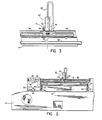
- FIG. 4 illustrates the clamp 28 pivotally joined to a support arm 30 which is resilient or is in turn pivotally connected to the case 18 and pulled downwardly by a tensioning spring 32.
- the opposite clamp 26 is similarly mounted and drawn downwardly against the sign material by means of a support arm 34 and spring 36 as shown in Fig. 2.
- a guide bar 38 extends in front of the feed roller 20 in parallel relationship with the roller to additionally hold the sign material and guide the material on and off of the feed roller as a cutting or plotting operation takes place.
- a similar guide bar 41 is located behind the feed roller as shown in Fig. 4 for the same purposes.
- the sign material M can be fed through the apparatus in sheets or from supply rolls or from fan-folded stacks of material at each side of the machine.
- Composite movements of the tool head 12 in one coordinate direction parallel to the feed roller 20 and of the sign material on the feed roller in an orthogonal coordinate direction enable two dimensional characters to be created.
- letter characters can be formed, but the invention is not so limited and numeral characters and other arbitrary two dimensional sign characters can be created.
- a heated cutting tool 40 is shown mounted in the tool head 12 in Figs. 1-5 for cutting through thermoplastic sign material M to the underlying release liner L in a sign cutting operation.
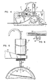
- the cutting tool shown in detail in Fig. 5 includes a body 46 having a heating rod 48 projecting from its lower end and a needle or stylus 50 which receives heat from the rod to cut through the thermoplastic sign material M.
- Power for the heat is supplied through the cable 52, and the controls for the apparatus shown in Fig. 1 include an on/off switch 54 and a selector switch 56 for high or low levels of heat.
- a variable control 58 shown in Fig. 13 can be used to regulate a variable transformer connected with the tool 40 or to switch terminals on multi-tap transformer in stepwise fashion.
- the heat level selectability is desirable for materials of different thickness and also for various cutting speeds. For example, a thin vinyl is more easily penetrated by the heated stylus 50 than a thicker vinyl, and to prevent the stylus from burning and penetrating the liner L in addition to the vinyl, a lower level of heat is selected. Thus, after cutting, the sign characters remain integrally secured to and are carried by the liner with the same spacing and positional relationship as cut.
- the cutting tool is mounted at the outer end of a support arm 60 which is connected to the rear portion of the head 12 by means of a hinge pin 62 shown in Fig. 4 extending parallel to the roller 20.
- the arm supports the tool with the central tool axis 64 extending in intersecting relationship with the axis 66 of rotation of the feed roller 20 and serves as a light weight platform allowing the tool 40 to press gently on the vinyl material M under the weight of the tool.
- the bridging portion of the arm 60 passes over a rotary lifting cam 66, and the cam is rotated by means of a lifting motor 68 to lower and raise the cutting tool 40 in and out of cutting engagement with the sign material.
- the cam has a lifting lobe 70, and when the lobe is rotated from the solid line position to the phantom position, the arm 60 is lifted along with the cutting tool. Rotation of the lobe to the solid line position disengages the cam and arm to allow the heated stylus 50 to penetrate through the vinyl material under the weight of the cutting tool.
- the feed roller 20 includes a hard rubber outer sleeve 22 which defines the support surface underlying the sign material M and liner L during a cutting operation.
- the sleeve is rigidly secured to the inner portion of the roller for rotation about the roller axis and the support surface of the sleeve extends circumaxially about the roller axis to hold and position the sheet material properly for working by the tool.
- the feed roller 20 is rotatably driven by means of a servomotor 80 shown in Fig. 2.
- the motor is connected in driving relationship with the roller through a gear reduction unit 82 and is actuated in response to command signals from a microprocessor described below to move the material back and forth under the cutting tool 40.
- the tool head 12 comprises a tool carriage that is moved back and forth on the ways 14, 16 by means of another servomotor 86 and a tool head drive belt 88 threaded around pulleys 90 (only one shown) at opposite ends of the ways.
- the one end of the drive belt connects with the tool carriage at one side and the other end of the belt connects with the carriage at the opposite side as shown most clearly in Fig 3.
- the servomotor 86 moves the tool 40 back and forth relative to the sheet material and feed roller in response to command signals from the microprocessor.
- Both of the servomotors 80, 86 include position transducers for accurately locating the cutting tool on the sign material at each point along the cut contours which outline the sign characters as shown in Fig. 1.
- control cables for the lift motor and also for supplying power to the heated cutting tool 40 are preferably in the form of a ribbon wire which may roll and unroll in a trough supported adjacent the head as the head moves back and forth over the feed roller 20.
- the group of five switches 92 shown on the case 18 in Fig. 1 enable the servomotors 80, 86 to be manually energized for disengaging the automatic controls and slewing the cutting tool 40 to any desired position over the sign material M.
- Each of the switches is associated with either the material or the cutting tool. Two of the switches move the material in one direction or the other under the cutting tool, another two of the switches move the cutting tool in one direction or the other on the ways 14, 16, and the fifth switch is used to raise and lower the cutting tool.
- a scale may be fixedly attached to the case 18 in parallel relationship with the ways 14, 16 to allow the plotting and cutting head 12 to be manually slewed more accurately to given positions along the feed roller 20.
- a sixth switch 94 is provided to operate the cutting tool 40 in a tool-down position and separate one portion of the material enveloping a sign from the surrounding material.
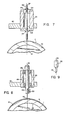
- the plotting and cutting head 12 is adapted to support not only the cutting tool 40, but also a plotting tool 100 as shown in Fig. 7. It will be observed, for example, in Figs. 5 and 7 that the tools are threadably secured in an aperture at the projecting end of the lifting arm 60 along a common tool axis 64.
- the plotting tool 100 is typically a pressurized ball point pen, and is held in the arm by means of a threaded bushing 102 having two screw caps 104,106 at opposite ends.
- An elastomeric ring 108 tightly surrounds and secures the pen adjacent the upper cap 104 to lift the pen away from the feed roller 20 when the lifting arm 60 is raised.
- a snap ring or ferrule 110 surrounds the pen adjacent the lower cap 106 to apply downward pressure to the pen through springs or the weight of the arm and bushing to mark a plotting paper P trained over the feed roller 20 on the hard sleeve 22.
- the sleeve serves as a hard backing material to permit the pen to produce marks on the paper as relative movement between the pen and paper is produced manually through the switches 92 or automatically through the microprocessor. If necessary, hold down springs may be connected with the lifting arm 60 to ensure that the plotting pen is urged into engagement with the plotting paper with sufficient pressure to produce a mark on the paper.
- the tool head 12 which permits both cutting and plotting tools to be used interchangeably on different work materials is advantageous in the sign making apparatus since the pin permits a programmed sign to be previewed on relatively inexpensive plotting paper P prior to actually cutting the sign text in the more expensive sign material M adhesively secured to a realease liner. Previewing the sign and the operation of the apparatus allows the machine operator to eliminate errors and make fine adjustments in the positioning and spacing of the text characters with minimal expense. Even if the cost differential between the sign material and plotting paper were not significant, the interchangeability of the cutting tool and the plotting tool is desirable because the plotting tool can be moved at a much higher speed then the cutting tool and thus proofing steps can be performed in a much shorter period of time than the actual cutting of the sign.
- Figs. 8 and 9 illustrate another cutting tool 120 that may be mounted in the lifting arm 60 in place of the cutting tool 40 and the plotting tool 100.
- the cutting tool 100 is comprised by a small scalpel blade which has a sharp cutting edge at its depending end.
- the blade is held in a chuck 122 by means of a clamping screw 124.
- the chuck is held in a threaded bushing 126 by means ballbearings 128, 129 so that the scalpel blade will freely rotate about the tool axis 64 as the direction of the cut in the sign material M is varied.
- the lower tip of the cutting edge is offset from the tool axis 64 and in this configuration, the lower edge is rotated into a trailing position behind the axis 64 in alignment with a line of cut as changes in direction take place.
- the scalpel or knife blade 120 may be used in place of the heated stylus 50 in Figs. 1-4 to cut large size characters in which small fillets or rounds caused by the rotations of the blade are not critical.
- the knife blade 120 is preferable for large characters because the maximum cutting speed of the scalpel is much greater than the heated stylus and the total time to cut a large character is correspondingly reduced. With small characters, however, the overall time is not significantly affected by the lower maximum speed of the heated stylus, and the ability of the stylus to accurately produce fine detail is clearly superior to the knife blade.
- an oriented cutting blade 121 may be utilized in the tool head 12 as shown in Fig. 10.
- the blade 121 has a sharp leading cutting edge in the same manner as the knife blade 120, but the blade 121 is positioned with the lowermost tip substantially concentric with the tool axis 64.
- the upper end of the chuck 122 is connected through a system of pulleys and toothed drive belt 123 with an orientation servo motor 125 mounted on the tool head.
- the servo motor receives blade orientation signals from the microprocessor to orient the blade in the direction of relative movement produced by the servo motors 80, 86 connected with the roller 20 and the tool head, respectively.
- Figs. 5-10 In addition to the cutting and plotting tools described in Figs. 5-10, other tools such reciprocating needles and spark gap tools may be used for pouncing or perforating materials along the profile of each sign character.
- Pouncing is sometimes employed by sign makers for dusting the outline of the letters onto a sign board or other object. The object is covered with an appropriately perforated overlay and then dabbed with a dusting pad to deposit slight traces of dust through the perforations on the object along the outline of the characters.
- the stylus 50 without heating and the lifting motor 68 may be operated as a pouncing tool.
- the lifting cam 66 and a holddown spring (not shown) reciprocate the support arm 60 and the stylus in a cyclic manner and produce a series of perforations along the outline of a character traced by the tool head 12 and feed roller 20.
- FIG. 11 and 12 Another pouncing tool employing the orientation motor 125 of Fig. 10 and a steerable yoke 119 in the bearings is shown in Figs. 11 and 12.
- the tool includes a pouncing wheel 127 having a plurality of radially extending needles or punch pins 117 which are pushed through a plotting paper P or similar material as the wheel rolls to produce the series of perforations outlining the sign characters. Relative movement between the wheel and paper is controlled by the servo motors 80,86 in the same manner as in plotting or cutting to mark the character outlines, and the orientation motor 125 ensures that the wheel 127 is properly oriented at each point of a contour.
- the sign making apparatus 10 offers the versatility of interchangeable tools for a variety of operations associated with the production of signs.
- the sign generating apparatus 10 in the preferred embodiment of Fig. 1 has a microprocessor-based design with a data keyboard 130 for entering the sign text, a function control keyboard 132 for controlling data entry and machine operations and a visual display 134.
- the data keyboard 130 is similar to a standard typewriter keyboard and enables the machine operator to identify the sign text characters and compose the text of a sign from a selected font of characters.
- an apparatus which permits sign text to be drawn cut or outlined for pouncing in a sign material with the same positioning and spacing of the text characters as desired in the final product on a sign board or other object.
- a plurality of characters having different proportions, sizes and special effects such as slant, can be generated, whereas with the prior art machines, different sets of dies would be required for each variation.
- the machine is obviously far more compact than the die cutting machines and in one embodiment occupies a space no larger than a xerographic copying machine.
- the interchangeable tool head is desirable in order to permit both proofing, cutting and pouncing a composed sign; however, a single purpose head which either plots, cuts or perforates a sign may be installed in the machine.
Landscapes
- Engineering & Computer Science (AREA)
- Life Sciences & Earth Sciences (AREA)
- Mechanical Engineering (AREA)
- Forests & Forestry (AREA)
- General Physics & Mathematics (AREA)
- Theoretical Computer Science (AREA)
- Physics & Mathematics (AREA)
- Automation & Control Theory (AREA)
- General Engineering & Computer Science (AREA)
- Control Of Cutting Processes (AREA)
- Perforating, Stamping-Out Or Severing By Means Other Than Cutting (AREA)
- Control Of Eletrric Generators (AREA)
- Numerical Control (AREA)
- Lubricants (AREA)
- Details Of Cutting Devices (AREA)
- Management, Administration, Business Operations System, And Electronic Commerce (AREA)
- Electronic Switches (AREA)
- Telephone Function (AREA)
- External Artificial Organs (AREA)
- Treatment Of Fiber Materials (AREA)
- Dot-Matrix Printers And Others (AREA)
- Sorption Type Refrigeration Machines (AREA)
- Iron Core Of Rotating Electric Machines (AREA)
- On-Site Construction Work That Accompanies The Preparation And Application Of Concrete (AREA)
- Saccharide Compounds (AREA)
- Holo Graphy (AREA)
- Light Sources And Details Of Projection-Printing Devices (AREA)
- Surgical Instruments (AREA)
- Non-Portable Lighting Devices Or Systems Thereof (AREA)
- Accessory Devices And Overall Control Thereof (AREA)
- Compositions Of Oxide Ceramics (AREA)
- Cephalosporin Compounds (AREA)
- Camera Data Copying Or Recording (AREA)
- Electrical Discharge Machining, Electrochemical Machining, And Combined Machining (AREA)
- Control And Other Processes For Unpacking Of Materials (AREA)
Claims (7)
dadurch gekennzeichnet, daß der Materialträger aus einer drehbaren Walze (20) besteht, deren Drehachse in einer Richtung verläuft und deren zylindrische, für den Arbeitsein griff bestimmte Oberfläche die Walzenachse umschreibt, über welche Oberfläche ein flexibler Streifen aus dem blattförmigen Material während der Schneid-oder Zeichenvorgänge geführt wird, um Zeichen vergrößerter Länge herzustellen;
Priority Applications (1)
| Application Number | Priority Date | Filing Date | Title |
|---|---|---|---|
| AT83106132T ATE56177T1 (de) | 1982-07-26 | 1983-06-23 | Automatisch arbeitende vorrichtung zur herstellung von zeichen. |
Applications Claiming Priority (2)
| Application Number | Priority Date | Filing Date | Title |
|---|---|---|---|
| US401722 | 1982-07-26 | ||
| US06/401,722 US4467525A (en) | 1982-07-26 | 1982-07-26 | Automated sign generator |
Related Child Applications (2)
| Application Number | Title | Priority Date | Filing Date |
|---|---|---|---|
| EP88102220.6 Division-Into | 1988-02-16 | ||
| EP88102265.1 Division-Into | 1988-02-17 |
Publications (3)
| Publication Number | Publication Date |
|---|---|
| EP0101814A2 EP0101814A2 (de) | 1984-03-07 |
| EP0101814A3 EP0101814A3 (en) | 1985-04-03 |
| EP0101814B1 true EP0101814B1 (de) | 1990-09-05 |
Family
ID=23588946
Family Applications (3)
| Application Number | Title | Priority Date | Filing Date |
|---|---|---|---|
| EP83106132A Expired - Lifetime EP0101814B1 (de) | 1982-07-26 | 1983-06-23 | Automatisch arbeitende Vorrichtung zur Herstellung von Zeichen |
| EP88102220A Expired - Lifetime EP0276026B1 (de) | 1982-07-26 | 1983-06-23 | Vorrichtung zur automatischen Herstellung von Zeichenbilder |
| EP88102265A Expired - Lifetime EP0276027B1 (de) | 1982-07-26 | 1983-06-23 | Vorrichtung zum Schneiden von Bögen |
Family Applications After (2)
| Application Number | Title | Priority Date | Filing Date |
|---|---|---|---|
| EP88102220A Expired - Lifetime EP0276026B1 (de) | 1982-07-26 | 1983-06-23 | Vorrichtung zur automatischen Herstellung von Zeichenbilder |
| EP88102265A Expired - Lifetime EP0276027B1 (de) | 1982-07-26 | 1983-06-23 | Vorrichtung zum Schneiden von Bögen |
Country Status (11)
| Country | Link |
|---|---|
| US (1) | US4467525A (de) |
| EP (3) | EP0101814B1 (de) |
| JP (2) | JPH0630048B2 (de) |
| AT (3) | ATE56908T1 (de) |
| AU (1) | AU563752B2 (de) |
| CA (1) | CA1195233A (de) |
| DE (3) | DE3381914D1 (de) |
| DK (1) | DK167604B1 (de) |
| ES (2) | ES523545A0 (de) |
| FI (1) | FI82895C (de) |
| NO (1) | NO169033C (de) |
Families Citing this family (91)
| Publication number | Priority date | Publication date | Assignee | Title |
|---|---|---|---|---|
| US4532521A (en) * | 1983-03-18 | 1985-07-30 | Brother Kogyo Kabushiki Kaisha | Recording apparatus |
| US4834276A (en) * | 1983-08-05 | 1989-05-30 | Gerber Scientific Products, Inc. | Web loading and feeding system, related web construction and method and apparatus for making web |
| JPS60116450A (ja) * | 1983-11-30 | 1985-06-22 | Brother Ind Ltd | 記録装置 |
| EP0149320B1 (de) * | 1983-12-29 | 1991-07-10 | Matsushita Electric Industrial Co., Ltd. | Stiftschreiber |
| EP0152586A3 (de) * | 1984-02-17 | 1988-06-08 | F. Wieland Elektrische Industrie GmbH | Vorrichtung zur Kennzeichnung von Kleinteilen |
| US4768410A (en) * | 1985-09-20 | 1988-09-06 | Gerber Scientific Products, Inc. | Coded web and associated web handling and working machine |
| US4708901A (en) * | 1985-09-20 | 1987-11-24 | Gerber Scientific Products, Inc. | Coded web and associated web handling and working machine |
| GB2184098B (en) * | 1985-12-13 | 1989-11-29 | Gerber Scient Inc | Web loading and feeding system |
| US4867363A (en) * | 1985-12-13 | 1989-09-19 | Gerber Scientific Products, Inc. | Web loading and feeding system |
| ES8704018A1 (es) * | 1985-12-20 | 1987-04-01 | Investronica Sa | Maquina automatica de dibujo y rayado de laminas de plasti- co |
| GB2187023B (en) * | 1986-02-24 | 1990-03-14 | Gerber Scient Inc | A method of using a laminated sign making web |
| US4725961A (en) * | 1986-03-20 | 1988-02-16 | Gerber Garment Technology, Inc. | Method and apparatus for cutting parts from pieces of irregularly shaped and sized sheet material |
| US4799172A (en) * | 1986-04-30 | 1989-01-17 | Gerber Scientific Products, Inc. | Apparatus and method for automatic layout of sign text |
| US4794542A (en) * | 1986-07-02 | 1988-12-27 | Jules Prockter | Sign generating apparatus with input of second sign information while cutting a first sign |
| US4734987A (en) * | 1987-02-26 | 1988-04-05 | Hewlett-Packard Company | Moving node wave isolator for drafting plotters |
| US4732069A (en) * | 1987-05-08 | 1988-03-22 | Gerber Scientific Products, Inc. | Knife and knife holder assembly |
| US5026584A (en) * | 1987-05-29 | 1991-06-25 | Gerber Scientific Products, Inc. | Sign making web with dry adhesive layer |
| US5288358A (en) * | 1987-05-29 | 1994-02-22 | Gerber Scientific Products, Inc. | Sign making web with dry adhesive layer and method of using the same |
| US4745683A (en) * | 1987-06-08 | 1988-05-24 | Gerber Scientific Products, Inc. | Apparatus for producing a pounce pattern |
| DE3729208C1 (de) * | 1987-08-29 | 1988-12-22 | Rotring Werke Riepe Kg | Schneidvorrichtung |
| US4905015A (en) * | 1988-05-18 | 1990-02-27 | Sieber Jonathan D | Apparatus and method for generating a variable line width |
| JP2527460B2 (ja) * | 1988-05-20 | 1996-08-21 | アルプス電気株式会社 | 切断装置 |
| US4932577A (en) * | 1988-08-22 | 1990-06-12 | Weiss Frederick S | Friction feed media driver for a sign plotter |
| US4910871A (en) * | 1989-02-16 | 1990-03-27 | Gerber Scientific Products, Inc. | Calligraphy machine and related method of operation |
| FR2647386A1 (fr) * | 1989-03-22 | 1990-11-30 | Isermatic France Sa | Dispositif de tracage et de coupe partielle en epaisseur d'un complexe multicouche adhesif protege et machine en faisant application |
| JPH0343187A (ja) * | 1989-07-11 | 1991-02-25 | Mimaki Eng:Kk | カッテングプロッタのカッタの刃先方向修正法 |
| US4996651A (en) * | 1989-12-22 | 1991-02-26 | Wells William L | Cutting instrument improvement for X-Y plotter |
| US5073424A (en) * | 1990-01-31 | 1991-12-17 | Dressler Donald R | Multi-colored one-step sign |
| US5236752A (en) * | 1990-01-31 | 1993-08-17 | Dressler Donald R | Web for making a multi-colored sign |
| JPH0486298A (ja) * | 1990-07-31 | 1992-03-18 | Mimaki Eng:Kk | プロッタ |
| US5143576A (en) * | 1990-08-10 | 1992-09-01 | Gerber Scientific Products, Inc. | Automatic weeding system and method of use |
| US5163759A (en) * | 1990-10-10 | 1992-11-17 | Brady Usa, Inc. | Signmaking machine using character forming tool for overlapping impacts and web scoring |
| US5275077A (en) * | 1991-02-27 | 1994-01-04 | Mimaki Engineering Co., Ltd. | Method of forming perforated cut line by cutting plotter |
| US5615123A (en) * | 1991-04-02 | 1997-03-25 | Creatacard, Inc. | System for creating and producing custom card products |
| US5304410A (en) * | 1991-05-02 | 1994-04-19 | Gerber Scientific Products, Inc. | Cutting cloth web having mounted backing material and related method |
| US5315690A (en) * | 1991-08-19 | 1994-05-24 | Gerber Scientific Products, Inc. | Method and associated apparatus for use with an automated sign generator to produce enhanced graphics |
| US5634388A (en) * | 1991-10-02 | 1997-06-03 | Kabushiki Kaisha Tokyo Horaisha | Mark cutting apparatus and method of controlling same |
| US5344680A (en) * | 1991-10-09 | 1994-09-06 | Gerber Scientific Products, Inc. | Sign making web with tack killing overcoat removable by washing and related method |
| US5213656A (en) * | 1991-12-04 | 1993-05-25 | Gerber Scientific Products, Inc. | Method of using a web for etching of a surface |
| CH685433A5 (de) * | 1991-12-16 | 1995-07-14 | Richard Voegele | Gerät zum Schneiden von Isolationsmaterial. |
| EP0561027B1 (de) * | 1992-03-19 | 1995-12-06 | ROTRING INTERNATIONAL GMBH & Co KG | Air-Brush Zeichen- und Schneidplotter |
| JPH06124078A (ja) * | 1992-10-13 | 1994-05-06 | Max Co Ltd | 欧文文書処理に於けるカーニング処理方法 |
| FR2697821B1 (fr) * | 1992-11-10 | 1995-01-27 | Gravograph Ind Internal | Procédé de découpe en continu de bande de matériau, notamment plastique, en vue de réaliser par exemple des pochoirs, et dispositif pour la mise en Óoeuvre du procédé. |
| US5537135A (en) * | 1993-01-22 | 1996-07-16 | Gerber Scientific Products, Inc. | Method and apparatus for making a graphic product |
| ATE188153T1 (de) * | 1993-03-15 | 2000-01-15 | Mabi Ag | Vorrichtung und verfahren zur dünnblechbearbeitung |
| US5421261A (en) * | 1993-04-27 | 1995-06-06 | Gerber Scientific Products, Inc. | Printing apparatus having web-cleaning members for removing particles affecting print quality |
| JPH077899U (ja) * | 1993-07-02 | 1995-02-03 | マックス株式会社 | 自動改行機能を備えたカッティング装置 |
| US5818492A (en) * | 1994-05-12 | 1998-10-06 | Minnesota Mining And Manufacturing Company | Method and system for thermal graphic printing |
| US5521480A (en) | 1994-09-01 | 1996-05-28 | Gerber Scientific Products, Inc. | Apparatus and method for defining a reference position of a tool |
| DE19508587A1 (de) * | 1995-03-13 | 1996-09-19 | Staedtler Fa J S | Vorrichtung zum Schneiden oder Ritzen, insbesondere für Plotter und/oder für sonstige, vorzugsweise automatische, Schreib-, Zeichen-, Ritz- oder Schneidanlagen oder -geräte |
| US5986686A (en) * | 1995-05-12 | 1999-11-16 | Gerber Scientific Produccts, Inc. | Apparatus for making graphic products having a platen drive with encoded sprockets |
| IT1283800B1 (it) * | 1995-09-01 | 1998-04-30 | Burr Oak Tool & Gauge | Dispositivo di taglio stazionario e spostabile in modo graduato |
| US5841464A (en) | 1995-10-25 | 1998-11-24 | Gerber Scientific Products, Inc. | Apparatus and method for making graphic products by laser thermal transfer |
| US5724084A (en) | 1995-12-05 | 1998-03-03 | Gerber Scientific Products, Inc. | Apparatus for making graphic products having a calibrated print head, and method of calibrating same |
| DE19630096C2 (de) * | 1996-07-25 | 1998-07-09 | Georg Geis Maschinenfabrik | Vorrichtung zum räumlichen Schneiden von dünnwandigen Formteilen |
| US5810494A (en) * | 1996-09-06 | 1998-09-22 | Gerber Systems Corporation | Apparatus for working on sheets of sheet material and sheet material for use therewith |
| US5846005A (en) * | 1996-09-09 | 1998-12-08 | Primera Technology, Inc. | Label printer with cutter attachment |
| US5868507A (en) * | 1997-04-09 | 1999-02-09 | Gerber Scientific Products, Inc. | Plotter having sprockets for driving sheets relative to a tool carriage and a fixed sheet support extending between the sprockets |
| US6106645A (en) * | 1998-01-21 | 2000-08-22 | Gerber Scientific Products, Inc. | Method and apparatus for manufacturing a graphic product |
| US6190297B1 (en) * | 1998-12-04 | 2001-02-20 | Gerber Scientific Products, Inc. | Apparatus for cutting and creasing sheet material |
| US20020108477A1 (en) * | 2001-02-09 | 2002-08-15 | Seniff Dana W. | Method for cutting coating blankets from sheet-type work material |
| US7250092B2 (en) * | 2001-12-05 | 2007-07-31 | Ferrell Randall W | Adhesive sign and methods for applying and producing same |
| US7325916B2 (en) * | 2002-02-08 | 2008-02-05 | Gerber Scientific International, Inc. | Method and apparatus for making signs |
| JP2005516803A (ja) * | 2002-02-08 | 2005-06-09 | ガーバー サイエンティフィック プロダクツ インコーポレイテッド | 画像形成方法及び画像形成装置 |
| US7040204B2 (en) * | 2002-10-30 | 2006-05-09 | Mikkelsen Graphic Engineering | Method for preparing graphics on sheets |
| CA2515356C (en) | 2003-02-06 | 2011-06-07 | Sulzer Chemtech Ag | Tray apparatus, column with same and method of assembling and using |
| US20050051011A1 (en) * | 2003-06-23 | 2005-03-10 | Seiko Epson Corporation | Cutting device for recording medium and recording apparatus incorporating the same |
| US7066671B2 (en) * | 2003-07-02 | 2006-06-27 | Adam Jude Ahne | Method for forming perforations in a sheet of media with a perforation system |
| US20050178254A1 (en) * | 2003-07-02 | 2005-08-18 | Lexmark International Inc. | Method for setting a location of an incising boundary around one or more objects |
| US7204654B2 (en) * | 2003-07-02 | 2007-04-17 | Lexmark International, Inc. | Perforation forming mechanism for use in an imaging apparatus |
| US7054708B1 (en) * | 2003-11-05 | 2006-05-30 | Xyron, Inc. | Sheet material cutting system and methods regarding same |
| US20070227332A1 (en) * | 2004-11-15 | 2007-10-04 | Xyron, Inc. | Automatic pattern making apparatus |
| EP1830988B1 (de) * | 2004-11-15 | 2010-10-13 | Xyron, Inc. | Automatische vorrichtung zur musterherstellung |
| JP3818451B2 (ja) * | 2004-11-22 | 2006-09-06 | 日東電工株式会社 | 積層体の切断方法 |
| US7625146B2 (en) * | 2005-03-30 | 2009-12-01 | Xerox Corporation | Method and system for custom paper cutting |
| WO2006110489A2 (en) * | 2005-04-08 | 2006-10-19 | University Of Utah Research Foundation | Rapid prototyping of microstructures using a cutting plotter |
| US7930958B2 (en) | 2005-07-14 | 2011-04-26 | Provo Craft And Novelty, Inc. | Blade housing for electronic cutting apparatus |
| US20070012148A1 (en) * | 2005-07-14 | 2007-01-18 | Robert Workman | Electronic cutting apparatus and methods for cutting |
| US20070034061A1 (en) * | 2005-07-14 | 2007-02-15 | Robert Workman | Electronic paper cutting apparatus and method for cutting |
| US20070012146A1 (en) * | 2005-07-14 | 2007-01-18 | Robert Workman | Electronic paper cutting apparatus and method |
| US7845259B2 (en) * | 2005-07-14 | 2010-12-07 | Provo Craft And Novelty, Inc. | Electronic paper cutting apparatus |
| JP2010516489A (ja) * | 2007-01-26 | 2010-05-20 | プロヴォ クラフト アンド ノヴェルティ インコーポレイテッド | 裁断装置 |
| CN101811271A (zh) * | 2009-02-19 | 2010-08-25 | 鸿富锦精密工业(深圳)有限公司 | 切削装置及其切削加工方法 |
| US20110280999A1 (en) | 2009-12-23 | 2011-11-17 | Provo Craft And Novelty, Inc. | Foodstuff Crafting Apparatus, Components, Assembly, and Method for Utilizing the Same |
| JP5546913B2 (ja) * | 2010-03-16 | 2014-07-09 | 株式会社尼崎工作所 | 平面状部材のトリミング装置とトリミング方法 |
| WO2018106784A2 (en) | 2016-12-07 | 2018-06-14 | Djg Holdings, Llc | Preparation of large area signage stack |
| US10152990B2 (en) * | 2016-12-08 | 2018-12-11 | Océ Holding B.V. | Flatbed cutter assembly and a method therefor |
| US11235555B2 (en) * | 2017-07-31 | 2022-02-01 | 3M Innovative Properties Company | Polymeric surfacing film having double outline defining geometric shapes therein |
| CH714676A2 (de) | 2018-02-23 | 2019-08-30 | Jentschmann Ag | Rollenplottersystem. |
| JP7322584B2 (ja) * | 2019-08-09 | 2023-08-08 | 株式会社リコー | シート加工装置、画像形成システム |
| JP7322582B2 (ja) * | 2019-08-09 | 2023-08-08 | 株式会社リコー | シート加工装置、画像形成システム |
Family Cites Families (29)
| Publication number | Priority date | Publication date | Assignee | Title |
|---|---|---|---|---|
| US1775813A (en) * | 1928-10-29 | 1930-09-16 | Vincent V Colby | Curve cutter |
| DE908458C (de) * | 1951-12-07 | 1954-04-05 | Optische Werke C A Steinheil S | Vorrichtung zum Feinmarkeren oder Beschriften von Schichten |
| DE1256569B (de) * | 1961-08-31 | 1967-12-14 | Zuse K G | Schwenkeinrichtung fuer ein Gravierwerkzeug |
| US3465627A (en) * | 1967-09-20 | 1969-09-09 | Coated Products Inc | Polytetrafluoroethylene coated hot cutting die |
| NL6808110A (de) * | 1968-06-08 | 1969-12-10 | ||
| DE2038374A1 (de) * | 1970-08-01 | 1972-04-20 | Hell Rudolf Dr Ing Fa | Verfahren und Anordnung zur modifizierten Aufzeichnung von Schrift- und/oder Bildzeichen |
| US3690011A (en) * | 1970-11-12 | 1972-09-12 | Burchell Wesley B | Variable pattern recorder |
| US3772949A (en) * | 1972-01-17 | 1973-11-20 | Gerber Scientific Instr Co | Method and apparatus for cutting sheet material |
| US3826167A (en) * | 1972-05-19 | 1974-07-30 | Pst Co | Sign forming apparatus, method and die for use therein |
| US3820121A (en) * | 1972-10-13 | 1974-06-25 | Gerber Scientific Instr Co | Apparatus for expressing a writing fluid |
| DE2356941A1 (de) * | 1972-11-22 | 1974-06-06 | Gerber Garment Technology Inc | Geraet zum zuschneiden von aus duennen schichten bestehenden werkstoffen |
| AU473068B2 (en) * | 1973-03-21 | 1976-06-10 | Binks-Bullows (Aust.) Pty. Ltd. | Spray-gun |
| US3857525A (en) * | 1973-04-20 | 1974-12-31 | Gerber Scientific Instr Co | Plotting system |
| JPS5018338A (de) * | 1973-06-22 | 1975-02-26 | ||
| JPS5158099A (ja) * | 1974-11-18 | 1976-05-21 | Ekusuroodo Ee Bii Aaru Kk | Kokokuyokirinukimoji oyobisono seizohoho |
| US3964591A (en) * | 1975-06-10 | 1976-06-22 | International Business Machines Corporation | Font selection system |
| JPS5234332A (en) * | 1975-09-11 | 1977-03-16 | Mitsubishi Electric Corp | System disturbance detector |
| NL7613358A (nl) * | 1976-12-01 | 1978-06-05 | Philips Nv | Besturingsinrichting voor een matrixdrukker. |
| JPS5856132B2 (ja) * | 1976-07-23 | 1983-12-13 | シチズン時計株式会社 | 電子計算機付腕時計のスイツチ |
| US4319253A (en) * | 1978-04-10 | 1982-03-09 | Heyer Inc. | Electronic stencil cutter |
| US4367588A (en) * | 1978-05-24 | 1983-01-11 | Herbert Thomas A | Process for cutting strippable film |
| JPS6027578B2 (ja) * | 1978-05-30 | 1985-06-29 | シャープ株式会社 | 印字装置 |
| US4236835A (en) * | 1978-12-18 | 1980-12-02 | Printronix, Inc. | Printer system with compressed print capability |
| JPS5619798A (en) * | 1979-07-27 | 1981-02-24 | Tokyo Computer Control Kk | Cutting or drawing device in automatic drawing machine |
| US4331051A (en) * | 1979-09-10 | 1982-05-25 | Gerber Garment Technology, Inc. | Apparatus for cutting sheet material with variable gain closed loop |
| IT1119227B (it) * | 1979-10-17 | 1986-03-03 | Olivetti & Co Spa | Dispositivo di stampa a punti per macchina contabile terminale telescrivente e simile macchina per ufficio |
| US4358975A (en) * | 1980-05-23 | 1982-11-16 | Camsco, Inc. | Rotary chisel cutter |
| US4373412A (en) * | 1980-07-10 | 1983-02-15 | Gerber Garment Technology, Inc. | Method and apparatus for cutting sheet material with a cutting wheel |
| JPS5759292A (en) * | 1980-09-29 | 1982-04-09 | Canon Inc | Character processor |
-
1982
- 1982-07-26 US US06/401,722 patent/US4467525A/en not_active Expired - Lifetime
-
1983
- 1983-06-09 FI FI832081A patent/FI82895C/fi not_active IP Right Cessation
- 1983-06-14 NO NO832142A patent/NO169033C/no not_active IP Right Cessation
- 1983-06-21 DK DK287583A patent/DK167604B1/da not_active IP Right Cessation
- 1983-06-23 EP EP83106132A patent/EP0101814B1/de not_active Expired - Lifetime
- 1983-06-23 DE DE8888102220T patent/DE3381914D1/de not_active Expired - Lifetime
- 1983-06-23 AT AT88102220T patent/ATE56908T1/de not_active IP Right Cessation
- 1983-06-23 AT AT88102265T patent/ATE56648T1/de not_active IP Right Cessation
- 1983-06-23 ES ES523545A patent/ES523545A0/es active Granted
- 1983-06-23 EP EP88102220A patent/EP0276026B1/de not_active Expired - Lifetime
- 1983-06-23 EP EP88102265A patent/EP0276027B1/de not_active Expired - Lifetime
- 1983-06-23 DE DE8888102265T patent/DE3381896D1/de not_active Expired - Lifetime
- 1983-06-23 AT AT83106132T patent/ATE56177T1/de active
- 1983-06-23 DE DE8383106132T patent/DE3381863D1/de not_active Expired - Lifetime
- 1983-07-25 JP JP58135672A patent/JPH0630048B2/ja not_active Expired - Lifetime
- 1983-07-26 CA CA000433161A patent/CA1195233A/en not_active Expired
- 1983-12-09 ES ES527910A patent/ES8406928A1/es not_active Expired
-
1984
- 1984-03-15 AU AU25638/84A patent/AU563752B2/en not_active Ceased
-
1991
- 1991-07-31 JP JP19208791A patent/JPH0698594B2/ja not_active Expired - Lifetime
Also Published As
Similar Documents
| Publication | Publication Date | Title |
|---|---|---|
| US4467525A (en) | Automated sign generator | |
| US4512839A (en) | Multi-color sign making method and layup | |
| US4764880A (en) | Compound plotting apparatus and related method of operation | |
| EP0476398B1 (de) | Verfahren und Vorrichtung zum Etikettieren für eine Blattmaterialschneidevorrichtung | |
| DK167969B1 (da) | Langstrakt bane og apparat til fremfoering af denne i en maskine | |
| US4364330A (en) | Cutting apparatus with consumable marker | |
| CN210525173U (zh) | 一种切割机机头及切割机 | |
| US5259648A (en) | Label supply for use with a labelling apparatus for a sheet material cutting system | |
| US4745683A (en) | Apparatus for producing a pounce pattern | |
| US5315690A (en) | Method and associated apparatus for use with an automated sign generator to produce enhanced graphics | |
| GB2123579A (en) | A cutting system for sheet material | |
| EP0057964A1 (de) | Verfahren und Gerät zum Herstellen von einzeln zu übertragenden Symbolen |
Legal Events
| Date | Code | Title | Description |
|---|---|---|---|
| PUAI | Public reference made under article 153(3) epc to a published international application that has entered the european phase |
Free format text: ORIGINAL CODE: 0009012 |
|
| AK | Designated contracting states |
Designated state(s): AT BE CH DE FR GB IT LI LU NL SE |
|
| PUAL | Search report despatched |
Free format text: ORIGINAL CODE: 0009013 |
|
| AK | Designated contracting states |
Designated state(s): AT BE CH DE FR GB IT LI LU NL SE |
|
| 17P | Request for examination filed |
Effective date: 19851002 |
|
| 17Q | First examination report despatched |
Effective date: 19861201 |
|
| R17C | First examination report despatched (corrected) |
Effective date: 19870703 |
|
| GRAA | (expected) grant |
Free format text: ORIGINAL CODE: 0009210 |
|
| AK | Designated contracting states |
Kind code of ref document: B1 Designated state(s): AT BE CH DE FR GB IT LI LU NL SE |
|
| REF | Corresponds to: |
Ref document number: 56177 Country of ref document: AT Date of ref document: 19900915 Kind code of ref document: T |
|
| ITF | It: translation for a ep patent filed | ||
| REF | Corresponds to: |
Ref document number: 3381863 Country of ref document: DE Date of ref document: 19901011 |
|
| RAP2 | Party data changed (patent owner data changed or rights of a patent transferred) |
Owner name: GERBER SCIENTIFIC PRODUCTS, INC. |
|
| ET | Fr: translation filed | ||
| PLBI | Opposition filed |
Free format text: ORIGINAL CODE: 0009260 |
|
| 26 | Opposition filed |
Opponent name: MAX CO. LTD Effective date: 19910605 Opponent name: ARISTO GRAPHIC SYSTEME GMBH & CO.KG Effective date: 19910604 Opponent name: SUMMAGRAPHICS CORPORATION Effective date: 19910605 |
|
| NLR1 | Nl: opposition has been filed with the epo |
Opponent name: MAX CO. LTD. Opponent name: ARISTO GRAPHIC SYSTEME GMBH & CO.KG. Opponent name: SUMMAGRAPHICS CORPORATION |
|
| ITTA | It: last paid annual fee | ||
| EPTA | Lu: last paid annual fee | ||
| EAL | Se: european patent in force in sweden |
Ref document number: 83106132.0 |
|
| PGFP | Annual fee paid to national office [announced via postgrant information from national office to epo] |
Ref country code: GB Payment date: 19950515 Year of fee payment: 13 Ref country code: CH Payment date: 19950515 Year of fee payment: 13 |
|
| PGFP | Annual fee paid to national office [announced via postgrant information from national office to epo] |
Ref country code: DE Payment date: 19950518 Year of fee payment: 13 |
|
| PGFP | Annual fee paid to national office [announced via postgrant information from national office to epo] |
Ref country code: AT Payment date: 19950520 Year of fee payment: 13 |
|
| PGFP | Annual fee paid to national office [announced via postgrant information from national office to epo] |
Ref country code: BE Payment date: 19950522 Year of fee payment: 13 |
|
| PGFP | Annual fee paid to national office [announced via postgrant information from national office to epo] |
Ref country code: NL Payment date: 19950524 Year of fee payment: 13 Ref country code: FR Payment date: 19950524 Year of fee payment: 13 |
|
| PGFP | Annual fee paid to national office [announced via postgrant information from national office to epo] |
Ref country code: SE Payment date: 19950529 Year of fee payment: 13 |
|
| APAC | Appeal dossier modified |
Free format text: ORIGINAL CODE: EPIDOS NOAPO |
|
| RDAG | Patent revoked |
Free format text: ORIGINAL CODE: 0009271 |
|
| STAA | Information on the status of an ep patent application or granted ep patent |
Free format text: STATUS: PATENT REVOKED |
|
| 27W | Patent revoked |
Effective date: 19950926 |
|
| GBPR | Gb: patent revoked under art. 102 of the ep convention designating the uk as contracting state |
Free format text: 950926 |
|
| REG | Reference to a national code |
Ref country code: CH Ref legal event code: PL |
|
| PGFP | Annual fee paid to national office [announced via postgrant information from national office to epo] |
Ref country code: LU Payment date: 19960501 Year of fee payment: 14 |
|
| NLR2 | Nl: decision of opposition | ||
| APAH | Appeal reference modified |
Free format text: ORIGINAL CODE: EPIDOSCREFNO |
|
| PLAB | Opposition data, opponent's data or that of the opponent's representative modified |
Free format text: ORIGINAL CODE: 0009299OPPO |