EP0101860B1 - Dispositif pour ajuster des plaques céramiques pour rayonnage d'empilement - Google Patents
Dispositif pour ajuster des plaques céramiques pour rayonnage d'empilement Download PDFInfo
- Publication number
- EP0101860B1 EP0101860B1 EP19830106862 EP83106862A EP0101860B1 EP 0101860 B1 EP0101860 B1 EP 0101860B1 EP 19830106862 EP19830106862 EP 19830106862 EP 83106862 A EP83106862 A EP 83106862A EP 0101860 B1 EP0101860 B1 EP 0101860B1
- Authority
- EP
- European Patent Office
- Prior art keywords
- alignment bar
- plates
- suspension
- cassette stack
- stack
- Prior art date
- Legal status (The legal status is an assumption and is not a legal conclusion. Google has not performed a legal analysis and makes no representation as to the accuracy of the status listed.)
- Expired
Links
- 239000000919 ceramic Substances 0.000 title claims description 8
- 239000000725 suspension Substances 0.000 claims description 13
- 238000003780 insertion Methods 0.000 claims description 3
- 230000037431 insertion Effects 0.000 claims description 3
- 230000006978 adaptation Effects 0.000 description 2
- 229910000639 Spring steel Inorganic materials 0.000 description 1
- 239000000463 material Substances 0.000 description 1
Images

Classifications
-
- B—PERFORMING OPERATIONS; TRANSPORTING
- B65—CONVEYING; PACKING; STORING; HANDLING THIN OR FILAMENTARY MATERIAL
- B65G—TRANSPORT OR STORAGE DEVICES, e.g. CONVEYORS FOR LOADING OR TIPPING, SHOP CONVEYOR SYSTEMS OR PNEUMATIC TUBE CONVEYORS
- B65G49/00—Conveying systems characterised by their application for specified purposes not otherwise provided for
- B65G49/05—Conveying systems characterised by their application for specified purposes not otherwise provided for for fragile or damageable materials or articles
- B65G49/08—Conveying systems characterised by their application for specified purposes not otherwise provided for for fragile or damageable materials or articles for ceramic mouldings
- B65G49/085—Conveying systems characterised by their application for specified purposes not otherwise provided for for fragile or damageable materials or articles for ceramic mouldings for loading or unloading racks or similar frames; loading racks therefor
Definitions
- the invention relates to a device for aligning, for example, unfired ceramic plates, which are provided one above the other in a stacking frame in order to be inserted into a cassette stack.
- unfired ceramic plates are placed in stacks of ceramic cassettes in order to be fired in these cassettes in a subsequent kiln.
- the cassettes or stack of cassettes are placed on kiln cars and driven through the kiln. If the cassette stack is used several times for a long time, it is often bent on one side, i.e. the stacks are vertically curved. This is due to some softening of the cassettes during burning and wear on the kiln cars so that the cassette stacks shift and become skewed. Difficulties arise when the cassette stacks are re-loaded with ceramic plates, which are provided in a stacking stand, because of the non-vertical alignment of the cassettes.
- the purpose of the invention is therefore to align the plates in the stacking frame so that they can be inserted freely into the cassettes without getting stuck. It is known to vertically prepare ceramic plates in the stacking stand by means of a transfer device, i.e. to change their altitude. Alignment with horizontal alignment of the position of the individual plates for vertical alignment of the plate stack while adapting to the vertical curvature of the cassette stack is not yet known.
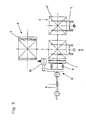
- the cassette stack 1 is brought to a loading station 3 on a base 2 (not explained in more detail), where plate stacks 4 made of ceramic plates 4 ′, which are ready, are inserted into the cassette stack 1 in a stacking stand 5 (FIG. 3).
- the movement of the stacking frame 5 to the cassette stack 1 takes place in the direction of the arrows shown in Figure 3 in a known manner and is not explained in detail.
- the horizontal position of the plates 4 'in the plate stack 4 i.e. the vertical alignment of the plate stack to the curvature of the cassette stack 1 is carried out by means of a straightening bar 7, which is made of flexible material, e.g. made of spring steel.
- the alignment bar 7 in the alignment device 6 is articulated in the embodiment shown on three suspensions 8.
- Each suspension 8 has an only schematically shown, generally designated 9 adjusting device with which the horizontal position of each suspension 8 can be adjusted.
- An electro-optical scanning device 10, for example a photocell, is arranged at the level of each suspension 8 and each of these suspensions.
- the stroke of each individual suspension 8 can be controlled by scanning the cassette stack 1 at the level of the respective suspension 8 with the photocell 10.
Landscapes
- Engineering & Computer Science (AREA)
- Ceramic Engineering (AREA)
- Furnace Charging Or Discharging (AREA)
- Sheets, Magazines, And Separation Thereof (AREA)
Claims (3)
Applications Claiming Priority (2)
| Application Number | Priority Date | Filing Date | Title |
|---|---|---|---|
| DE3227573 | 1982-07-23 | ||
| DE19823227573 DE3227573C2 (de) | 1982-07-23 | 1982-07-23 | Vorrichtung zum Ausrichten von ungebrannten keramis chen Platten in einem Stapelgerüst |
Publications (2)
| Publication Number | Publication Date |
|---|---|
| EP0101860A1 EP0101860A1 (fr) | 1984-03-07 |
| EP0101860B1 true EP0101860B1 (fr) | 1986-02-26 |
Family
ID=6169164
Family Applications (1)
| Application Number | Title | Priority Date | Filing Date |
|---|---|---|---|
| EP19830106862 Expired EP0101860B1 (fr) | 1982-07-23 | 1983-07-13 | Dispositif pour ajuster des plaques céramiques pour rayonnage d'empilement |
Country Status (2)
| Country | Link |
|---|---|
| EP (1) | EP0101860B1 (fr) |
| DE (1) | DE3227573C2 (fr) |
Family Cites Families (1)
| Publication number | Priority date | Publication date | Assignee | Title |
|---|---|---|---|---|
| DE2024189A1 (de) * | 1970-05-16 | 1971-12-09 | Villeroy & Boch Keramische Werke KG, 2400 Lübeck | Verfahren und Vorrichtung zum Füllen von Brennringen, Brennkapseln od.dgl. mit Fliesen, Platten od.dgl |
-
1982
- 1982-07-23 DE DE19823227573 patent/DE3227573C2/de not_active Expired
-
1983
- 1983-07-13 EP EP19830106862 patent/EP0101860B1/fr not_active Expired
Also Published As
| Publication number | Publication date |
|---|---|
| EP0101860A1 (fr) | 1984-03-07 |
| DE3227573C2 (de) | 1984-10-31 |
| DE3227573A1 (de) | 1984-02-02 |
Similar Documents
| Publication | Publication Date | Title |
|---|---|---|
| DE3112672C1 (de) | Anschlag fuer die Bogenhinterkante bei Bogenauslegern an bogenverarbeitenden Maschinen | |
| DE3341207C1 (de) | Beschickungsvorrichtung fuer einen Horizontal-Durchlaufofen zum Erwaermen von Glasscheiben | |
| DE3305081C2 (de) | Vorrichtung zum Vereinzeln des jeweils obersten Blattes eines Blattstapels | |
| DE3823806C2 (fr) | ||
| DE3706065C2 (fr) | ||
| EP0154892A1 (fr) | Installation pour la fabrication des feuilles de verre très bombées | |
| DE2838739C2 (de) | Vorrichtung zum Schneiden von Ziegelformlingen aus einem Strangstück | |
| EP0436506A1 (fr) | Dispositif pour aligner des piles | |
| EP0200120A2 (fr) | Dispositif d'introduction de pièces en forme de plaques déposées sur une table élévatrice dans une installation de séparation de plaques | |
| DE2715194C3 (de) | Vorrichtung zum Schwenken einer sich horizontal auf einem Luftkissentisch bewegenden Glasscheibe in ihrer Ebene | |
| EP0101860B1 (fr) | Dispositif pour ajuster des plaques céramiques pour rayonnage d'empilement | |
| EP0078873A2 (fr) | Dispositif de transfert automatique de substrats pour circuits électriques imprimés d'une zone de chargement à une installation d'impression | |
| DE19822458A1 (de) | Vorrichtung zum Anheben eines Stapels von Papierbögen zum Ladekopf einer Druckmaschine | |
| DE3223171C2 (fr) | ||
| DE1936778B2 (de) | Vorrichtung zum vereinzeln des jeweils untersten kartonzuschnitts aus einem stapel | |
| DE3537743A1 (de) | Stoffstapelvorrichtung fuer naehmaschinen | |
| DE2724345A1 (de) | Ablagefach zum lagerichtigen stapeln von dokumenten | |
| DE3047178A1 (de) | Vorrichtung zum transportieren und positionieren von druckformen | |
| DE4030643C2 (fr) | ||
| DE3335122A1 (de) | Vorrichtung zum handhaben von lagern | |
| DE3031661A1 (de) | Verfahren und vorrichtung zum selbsttaetigen stapeln von rohlingen fuer keramische formlinge, insbesondere dachziegel | |
| DE2525465B2 (de) | Verfahren und vorrichtung zum gleichzeitigen abnehmen mehrerer kernbleche von einem stapel | |
| DE3208772C2 (de) | Vorrichtung zur Bildung von Stapeln von Akkumulatorplatten | |
| DE2715801A1 (de) | Automatische glasscheiben-stapeleinrichtung | |
| AT314423B (de) | Vorrichtung zum Ent- und/oder Aufstapeln von magnetischen Blechzuschnitten |
Legal Events
| Date | Code | Title | Description |
|---|---|---|---|
| PUAI | Public reference made under article 153(3) epc to a published international application that has entered the european phase |
Free format text: ORIGINAL CODE: 0009012 |
|
| 17P | Request for examination filed |
Effective date: 19830713 |
|
| AK | Designated contracting states |
Designated state(s): FR GB IT NL |
|
| ITF | It: translation for a ep patent filed | ||
| GRAA | (expected) grant |
Free format text: ORIGINAL CODE: 0009210 |
|
| AK | Designated contracting states |
Designated state(s): FR GB IT NL |
|
| ET | Fr: translation filed | ||
| PLBE | No opposition filed within time limit |
Free format text: ORIGINAL CODE: 0009261 |
|
| STAA | Information on the status of an ep patent application or granted ep patent |
Free format text: STATUS: NO OPPOSITION FILED WITHIN TIME LIMIT |
|
| 26N | No opposition filed | ||
| PGFP | Annual fee paid to national office [announced via postgrant information from national office to epo] |
Ref country code: GB Payment date: 19940705 Year of fee payment: 12 |
|
| PGFP | Annual fee paid to national office [announced via postgrant information from national office to epo] |
Ref country code: FR Payment date: 19940722 Year of fee payment: 12 |
|
| ITTA | It: last paid annual fee | ||
| PGFP | Annual fee paid to national office [announced via postgrant information from national office to epo] |
Ref country code: NL Payment date: 19940731 Year of fee payment: 12 |
|
| PG25 | Lapsed in a contracting state [announced via postgrant information from national office to epo] |
Ref country code: GB Effective date: 19950713 |
|
| PG25 | Lapsed in a contracting state [announced via postgrant information from national office to epo] |
Ref country code: NL Effective date: 19960201 |
|
| GBPC | Gb: european patent ceased through non-payment of renewal fee |
Effective date: 19950713 |
|
| NLV4 | Nl: lapsed or anulled due to non-payment of the annual fee |
Effective date: 19960201 |
|
| PG25 | Lapsed in a contracting state [announced via postgrant information from national office to epo] |
Ref country code: FR Effective date: 19960430 |
|
| REG | Reference to a national code |
Ref country code: FR Ref legal event code: ST |
|
| REG | Reference to a national code |
Ref country code: FR Ref legal event code: ST |
|
| REG | Reference to a national code |
Ref country code: FR Ref legal event code: ST |