EP0101865A1 - Boîte pour les appareils d'actionnement et de commande des accessoires à commande électrique sur les camions, particulièrement pour les hayons élévateurs - Google Patents
Boîte pour les appareils d'actionnement et de commande des accessoires à commande électrique sur les camions, particulièrement pour les hayons élévateurs Download PDFInfo
- Publication number
- EP0101865A1 EP0101865A1 EP83106934A EP83106934A EP0101865A1 EP 0101865 A1 EP0101865 A1 EP 0101865A1 EP 83106934 A EP83106934 A EP 83106934A EP 83106934 A EP83106934 A EP 83106934A EP 0101865 A1 EP0101865 A1 EP 0101865A1
- Authority
- EP
- European Patent Office
- Prior art keywords
- housing
- cover
- box according
- wall
- support plate
- Prior art date
- Legal status (The legal status is an assumption and is not a legal conclusion. Google has not performed a legal analysis and makes no representation as to the accuracy of the status listed.)
- Granted
Links
Images


Classifications
-
- B—PERFORMING OPERATIONS; TRANSPORTING
- B60—VEHICLES IN GENERAL
- B60P—VEHICLES ADAPTED FOR LOAD TRANSPORTATION OR TO TRANSPORT, TO CARRY, OR TO COMPRISE SPECIAL LOADS OR OBJECTS
- B60P1/00—Vehicles predominantly for transporting loads and modified to facilitate loading, consolidating the load, or unloading
- B60P1/44—Vehicles predominantly for transporting loads and modified to facilitate loading, consolidating the load, or unloading having a loading platform thereon raising the load to the level of the load-transporting element
- B60P1/4471—General means for controlling movements of the loading platform, e.g. hydraulic systems
- B60P1/4478—Safety stops, switches
-
- H—ELECTRICITY
- H02—GENERATION; CONVERSION OR DISTRIBUTION OF ELECTRIC POWER
- H02B—BOARDS, SUBSTATIONS OR SWITCHING ARRANGEMENTS FOR THE SUPPLY OR DISTRIBUTION OF ELECTRIC POWER
- H02B1/00—Frameworks, boards, panels, desks, casings; Details of substations or switching arrangements
- H02B1/26—Casings; Parts thereof or accessories therefor
- H02B1/28—Casings; Parts thereof or accessories therefor dustproof, splashproof, drip-proof, waterproof or flameproof
Definitions
- the invention relates to a control and control box for electrically controlled additional devices of trucks, in particular tail lifts, which has the controls under a hinged cover in a housing and controls under a support plate.
- the control point for the manual operation of rear-mounted tail lifts or the like is located at the rear end of the body on the footpath side.
- Such chargers are usually operated hydraulically and controlled electrically using solenoid valves.
- solenoid valves In addition to foot control on the actual platform, manual control is required for the standing operator. This must be located near the tail lift and is therefore located behind the rear wheel in the largest dirt area. Not only when driving on wet roads, but also when washing in car washes and with steam jet devices, the control and control box is exposed to considerable water and pollution. So far, commercially available or specially made of sheet metal or the like. Boxes have been used, which usually contain a closure lid with a toggle handle.
- the lid So that the lid is not on your hands during operation or does not have to be secured by additional elements that are susceptible to wear, it is folded down.
- the control plate is usually vertical. Either the locking elements are worn or the locking is forgotten.
- the controls are exposed to considerable dirt.
- there would be a considerable risk of condensation which would affect the electrical functionality, because a truck is exposed to considerable temperature fluctuations, for example in heated garages on the one hand and at low outside temperatures on the other.
- the invention has for its object to provide a control and control box of the type mentioned, the splash and splash water protected, but is sufficiently ventilated so that no condensation forms, possibly penetrating water can drain, the controls are easy to use and easy to recognize contains and is provided with a lid that does not interfere with the operation and closes automatically even with slight driver shocks.
- the support plate which is arranged inclined at the top backwards is set back from the opening edge and at least the lower inner wall of the equipment compartment is inclined in the direction of the housing opening and preferably in the direction of the lower edge of the plate and at least the upper housing wall is at least has a splash water level or splash water rib and an upper articulated cover is provided which encompasses the housing opening on all sides and which is supported in the upper opening position only pivoted slightly beyond the top dead center.
- the housing has steps in all four side walls, which form an inclined support surface for the support plate on the inside, to the rear one in height and preferably also in width smaller than the control room designed device room, the walls of which are diverging in the direction of the step.
- Such an arrangement allows the water to drain off well and surge and splash water do not rise up to the control element space and penetrate from the front. In spite of this, water that has penetrated easily flows out of the equipment room.
- the support plate can be mounted cheaply.
- the lower wall of the housing can be designed to be inclined in the direction of a liquid channel or liquid opening. Any water that may be present does not run across the entire width in the area of the step, but into an even smaller trough-shaped space, which further reduces the evaporation surface.
- control element space is expediently delimited at the front by a vertically running control element space edge, over which the pivotable cover engages.
- the edge of the control element can expediently have an outwardly projecting splash water rib which, in addition to the step, can counteract the further penetration of water.
- the lid can expediently have a straight, preferably vertical front wall, a lower wall which is slightly inclined downwards towards the horizontal and which extends to the level of Housing ranges, such as trapezoidal side walls, which extend from the front wall to the surge water level of the housing, and have an upper wall which overlaps the upper splash water rib, but which is shorter than the upper regions of the side walls in such a way that its edge in the open position is on the other side the upper wall of the equipment room lying on the splash water level and supports the cover near the top dead center position.
- a lid design is inexpensive to manufacture and prevent the entry of water and secure coverage of the control element space and allows water to drain off favorably on its lower wall.
- the lid can be easily stored and properly supported at the center of gravity.
- An axis running through the side walls of the cover and the side walls of the control element space can be provided for the formation of all joints. This can take on an additional function by lying in the upper area in front of the support plate and holding it onto the contact surface of the step.
- a gas-permeable, elastic contact seal which preferably consists of foam rubber, can expediently be provided between the support plate and the contact surface.
- it secures the rattle-free fastening of the support plate, even if it is only held with contact elements, such as the push-through axis.
- it prevents water from entering the equipment compartment directly if water should be sprayed into the control element compartment while washing. In addition, however, it allows gas exchange with the equipment room, so that no condensation is formed in it. It also allows any water collected below to exit again.
- the support plate can be fastened in the lower area to the housing with screws, which preferably also secure a cover movement safeguard. This enables assembly with just a few screws. However, it can also be inserted behind retaining lugs in the lower area. So only the hinge axis has to be inserted and the number of parts is further reduced.
- the cover movement safeguard can consist of a latching device or a magnet holding device with simple magnets and metal plates.
- Housing and preferably also cover are expediently made of deep-drawn plastic material, preferably ABS-acrylonitrile-butadiene-styrene. Due to the favorable shape of the housing, which serves the purpose of accommodating and draining water, as well as being easy to install, the simple and inexpensive formability in the deep-drawing process is also guaranteed, which requires simple tools and yet ensures sufficient stability and security against all dangers during long-term operation . Cable entries are conveniently provided only in the side walls and the lower wall, so that the risk of unwanted water penetration is reduced. The attachment should also be provided in the area of the lower wall. Further details, refinements, features and advantages of the invention also result from the following description part, drawn up with reference to the drawings.
- the truck 10 according to FIG. 1 has a tail lift 11 at its rear, which is attached with links 12 to a mounting and drive part 13, which in turn is attached to the vehicle frame.
- an operating and control element box 15 is provided, which is fastened with a holding bracket 14 under the loading floor 10.1.
- a horizontal section 14.1 passes under the operating and control element box 15 and is fastened at a distance therefrom with screws which engage from below, so that no water can seep in through fastening holes from above.
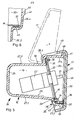
- the control and control element box 15 shown in more detail in FIGS. 2 to 6 has a housing 16, a cover 17 and a support plate 18.
- the support plate 18 divides a device space 19 and a control element space 20 from one another in the housing 16.
- control elements 22 for example rotary switches, pushbuttons or the like. They are fastened to the support plate 18 and the control elements 21; here, for example, rotary switch handles 21 are located in the control element space 20.
- rotary switch handles 21 are located in the control element space 20.
- two rotary switches are shown, as can be seen in FIG. 3. Lines, cables, other switching elements such as relays and the like are omitted for the sake of clarity.
- a cable entry 23 is shown, which can be-for example a sealed, inserted and tightly enclosing the cable grommet.
- the equipment compartment 19 is surrounded by a rear wall 25, two side walls 26.1 and 26.2, a lower wall 27.1 and an upper wall 27.2.
- a surge water level 28 which - as can be seen from FIGS. 2, 4 and 5 - is inclined.
- the rear wall 25 is vertical, while the lower wall 27.1 is inclined downwards to the horizontal 29 - as can be seen in FIG. 5 - towards the support plate 18 and at the same time towards the housing opening 30. It diverges with the upper wall 27.2 in the direction of the support plate 18. This serves to allow the water to run on the upper wall 27.2 in the direction of the rear wall 25, for example when driving in the rain or when washing. Water that has inadvertently entered the equipment compartment 19 can flow off on the lower wall 27.1 in the direction of the support plate 18 and the housing opening 30.
- the support plate 18 lies behind the hinge axis 38, which is arranged such that it presses the support plate 18 firmly onto the foam rubber strip 33 and thus onto the support surface 32.
- the control element space 20 is delimited on the outside by the upper wall 27.4, which adjoins the step 28.2 at the top and extends to the housing opening 30 and is also designed to drop slightly towards the bottom.
- Vertical sidewall portions 26.4 are trapezoidal and also range from the level '28 to the housing opening 30. You go there over in the operating room rim 40th This is formed vertically here, so that there is an elongated space designed in a trapezoidal vertical section, in which the operating elements 21 are well protected, easily accessible and clearly visible.
- the control element space edge 40 has a splash water rib 41 on the outside. This prevents water flowing from the side walls 26.3 and 26.4 and the upper wall 27.4 onto the housing opening 30.
- the entire housing is made of a suitable plastic, namely preferably Acrylonitrile-butadiene-styrene. It is a thermoplastic material that is easy to process in the deep-drawing process, even with a relatively large wall thickness, so that a box and rib thickness of about 3 to 5 mm can be achieved. Since the housing is deep-drawn from flat material, a material inflow and holding edge is required anyway. This then remains when the excess material is removed as splash water rib 41.
- a suitable plastic namely preferably Acrylonitrile-butadiene-styrene. It is a thermoplastic material that is easy to process in the deep-drawing process, even with a relatively large wall thickness, so that a box and rib thickness of about 3 to 5 mm can be achieved. Since the housing is deep-drawn from flat material, a material inflow and holding edge is required anyway. This then remains when the excess material is removed as splash water rib 41.
- the lower wall 27.3 of the control element space 20 is relatively short, but sufficient to hold the magnets, especially since the control elements are relatively high anyway and the space is free. It is only required on the support plate 18 as a surface for attaching operating instructions and the like.
- the wall 27.3 is also inclined to the horizontal so that water which enters the control element space 20 or passes through the foam rubber 33 in the region of the lower end or a space left in between can easily flow away.
- the housing opening 30 with its splash water rib 41 is - as can be seen particularly from FIGS. 4 and 5 - closed by a cover 17.
- This has a vertical cover front wall 45, which can, for example, carry the company logo of the manufacturer or the installing company, but is otherwise flat, can optionally be equipped with a handle and which, as can clearly be seen, merges into a lower wall 46 which is strongly inclined.
- the trapezoidal side walls 47 are formed integrally therewith, which extend over the entire visible surface and extend with curves into the lower wall 46 and the front wall 45 and embrace the splash water rib 41. Their limits extend to level 28, so that the lower wall 46 and the side walls in this area are relatively short, while the side walls in the upper area are relatively wide.
- a short top wall 48 is formed between the side walls 47 and the front wall 45, as is well illustrated in section in FIG. 5. It is formed in one piece with the other cover parts and also in the deep-drawing process, but only extends up to its supporting edge 49, which ends approximately in the first third as seen from the front wall 45 and merges there into the side walls reaching upwards. It overlaps the surge water rib 41 sufficiently so that rain or wash water coming from above is properly guided onto the upper wall 27.4 and 27.2 of the housing and does not penetrate into the housing opening 30.
- the position of the edge 49 is, however, dimensioned in relation to the axis 38 so that when the lid 17 is folded up - as indicated by dash-dotted lines in FIG.
- the edge 49 can extend beyond the step 28 and be supported on the upper wall 27.2.
- the axis 38 is guided through suitable bores in the side walls 26.3, 26.4 and 47.1 and 47.2 of the housing 16 and cover 17 and is secured with external nuts 38.1 or pins or the like.
- the position of the axis 38 as a hinge axis for the lid is chosen to the center of gravity S of the lid so that the lid in the upper opened position, when its top wall edge 49 is supported on the top wall 27.2 of the housing 16, just around the top dead center of the pivot position has moved a very small angular amount, for example a few mm, so that a just stable but almost unstable position is reached.
- the purpose of this arrangement is that the lid automatically remains open when the vehicle is at a standstill, but can be closed easily, especially if the closure has been forgotten, and closes automatically when the slightest vibration is caused by the movement of the vehicle. Since he, as can be seen, the Housing opening 30 encloses well on all sides, on the other hand, however, any water that may enter can drain off well, there is no fear of excessive moisture loading of the operating elements 21 even in heavy rain or in washing systems.
- the cover 17 is also made of the same material in the deep-drawing process as the housing. Both can also be injection molded from a suitable material or formed from sheet metal in the usual processes. The formal configurations can also differ.
- the embodiment shown is particularly simple in terms of structure and manufacture, inexpensive in terms of the arrangement of the operating elements and easy to manufacture, and is appealing in terms of shape.
- the lid can also be easily fitted with a lock.
Landscapes
- Engineering & Computer Science (AREA)
- Transportation (AREA)
- Mechanical Engineering (AREA)
- Power Engineering (AREA)
- Casings For Electric Apparatus (AREA)
- Vehicle Step Arrangements And Article Storage (AREA)
- Forklifts And Lifting Vehicles (AREA)
Priority Applications (1)
| Application Number | Priority Date | Filing Date | Title |
|---|---|---|---|
| AT83106934T ATE18873T1 (de) | 1982-08-02 | 1983-07-15 | Bedien- und steuerelementekasten fuer elektrisch gesteuerte zusatzgeraete von lastfahrzeugen, insbesondere von hubladebuehnen. |
Applications Claiming Priority (2)
| Application Number | Priority Date | Filing Date | Title |
|---|---|---|---|
| DE3228798 | 1982-08-02 | ||
| DE19823228798 DE3228798A1 (de) | 1982-08-02 | 1982-08-02 | Bedien- und steuerelementekasten fuer elektrisch gesteuerte zusatzgeraete von lastfahrzeugen, insbesondere von hubladebuehnen |
Publications (2)
| Publication Number | Publication Date |
|---|---|
| EP0101865A1 true EP0101865A1 (fr) | 1984-03-07 |
| EP0101865B1 EP0101865B1 (fr) | 1986-04-02 |
Family
ID=6169917
Family Applications (1)
| Application Number | Title | Priority Date | Filing Date |
|---|---|---|---|
| EP83106934A Expired EP0101865B1 (fr) | 1982-08-02 | 1983-07-15 | Boîte pour les appareils d'actionnement et de commande des accessoires à commande électrique sur les camions, particulièrement pour les hayons élévateurs |
Country Status (3)
| Country | Link |
|---|---|
| EP (1) | EP0101865B1 (fr) |
| AT (1) | ATE18873T1 (fr) |
| DE (2) | DE3228798A1 (fr) |
Cited By (3)
| Publication number | Priority date | Publication date | Assignee | Title |
|---|---|---|---|---|
| EP0408991A1 (fr) * | 1989-07-18 | 1991-01-23 | Siemens Aktiengesellschaft | Coffret d'appareillage pour des composants de circuits électriques et électromécaniques |
| EP1533178A3 (fr) * | 2003-11-19 | 2007-07-04 | MBB Liftsystems AG | Dispositif de commande pour l' hayon élévateur |
| EP3564071A1 (fr) * | 2018-05-04 | 2019-11-06 | Palfinger Tail Lifts GmbH | Dispositif de commande pour une plateforme de chargement par levage |
Citations (8)
| Publication number | Priority date | Publication date | Assignee | Title |
|---|---|---|---|---|
| US2511365A (en) * | 1948-08-19 | 1950-06-13 | Thomas E Murray | Switch box |
| US3477609A (en) * | 1968-10-24 | 1969-11-11 | Gen Dynamics Corp | Plastic box having snap cover with seal |
| US3847292A (en) * | 1972-06-08 | 1974-11-12 | F Gates | Automatic lift apparatus |
| US4102466A (en) * | 1975-02-06 | 1978-07-25 | Slater Electric Co. | Weatherproof receptacle cover and shield |
| DE2937029A1 (de) * | 1979-09-13 | 1981-04-02 | Wilhelm Stoll Maschinenfabrik Gmbh, 3325 Lengede | Ladebordwand mit sicherheitsschaltung |
| US4265365A (en) * | 1978-04-28 | 1981-05-05 | Slater Electric Inc. | Moisture resistant electrical outlet box |
| DE3024708A1 (de) * | 1980-06-30 | 1982-01-21 | Wilhelm Stoll Maschinenfabrik Gmbh, 3325 Lengede | Ladebordwand fuer lastkraftwagen |
| CA1120573A (fr) * | 1979-12-17 | 1982-03-23 | Northern Telecom Limited | Support pour materiel de test electrique |
Family Cites Families (1)
| Publication number | Priority date | Publication date | Assignee | Title |
|---|---|---|---|---|
| DE2150980C3 (de) * | 1971-10-13 | 1979-01-25 | Gebr. Happich Gmbh, 5600 Wuppertal | Elektrische Anschlußsteckdose |
-
1982
- 1982-08-02 DE DE19823228798 patent/DE3228798A1/de not_active Withdrawn
-
1983
- 1983-07-15 DE DE8383106934T patent/DE3362785D1/de not_active Expired
- 1983-07-15 AT AT83106934T patent/ATE18873T1/de not_active IP Right Cessation
- 1983-07-15 EP EP83106934A patent/EP0101865B1/fr not_active Expired
Patent Citations (8)
| Publication number | Priority date | Publication date | Assignee | Title |
|---|---|---|---|---|
| US2511365A (en) * | 1948-08-19 | 1950-06-13 | Thomas E Murray | Switch box |
| US3477609A (en) * | 1968-10-24 | 1969-11-11 | Gen Dynamics Corp | Plastic box having snap cover with seal |
| US3847292A (en) * | 1972-06-08 | 1974-11-12 | F Gates | Automatic lift apparatus |
| US4102466A (en) * | 1975-02-06 | 1978-07-25 | Slater Electric Co. | Weatherproof receptacle cover and shield |
| US4265365A (en) * | 1978-04-28 | 1981-05-05 | Slater Electric Inc. | Moisture resistant electrical outlet box |
| DE2937029A1 (de) * | 1979-09-13 | 1981-04-02 | Wilhelm Stoll Maschinenfabrik Gmbh, 3325 Lengede | Ladebordwand mit sicherheitsschaltung |
| CA1120573A (fr) * | 1979-12-17 | 1982-03-23 | Northern Telecom Limited | Support pour materiel de test electrique |
| DE3024708A1 (de) * | 1980-06-30 | 1982-01-21 | Wilhelm Stoll Maschinenfabrik Gmbh, 3325 Lengede | Ladebordwand fuer lastkraftwagen |
Non-Patent Citations (1)
| Title |
|---|
| PATENTS ABSTRACTS OF JAPAN, Band 3, Nr. 145 (E-155), Seite 6 E 155 & JP-A-54 122 842 (HITACHI SEISAKUSHO K.K.) 22.09.1979 * |
Cited By (3)
| Publication number | Priority date | Publication date | Assignee | Title |
|---|---|---|---|---|
| EP0408991A1 (fr) * | 1989-07-18 | 1991-01-23 | Siemens Aktiengesellschaft | Coffret d'appareillage pour des composants de circuits électriques et électromécaniques |
| EP1533178A3 (fr) * | 2003-11-19 | 2007-07-04 | MBB Liftsystems AG | Dispositif de commande pour l' hayon élévateur |
| EP3564071A1 (fr) * | 2018-05-04 | 2019-11-06 | Palfinger Tail Lifts GmbH | Dispositif de commande pour une plateforme de chargement par levage |
Also Published As
| Publication number | Publication date |
|---|---|
| DE3362785D1 (en) | 1986-05-07 |
| ATE18873T1 (de) | 1986-04-15 |
| EP0101865B1 (fr) | 1986-04-02 |
| DE3228798A1 (de) | 1984-02-02 |
Similar Documents
| Publication | Publication Date | Title |
|---|---|---|
| CH438052A (de) | Behälteranordnung für die Unterbringung von Skiern in Kraftwagen | |
| DE19622694B4 (de) | Flurförderzeug mit einem Batteriefach | |
| DE3607725C2 (fr) | ||
| EP0101865B1 (fr) | Boîte pour les appareils d'actionnement et de commande des accessoires à commande électrique sur les camions, particulièrement pour les hayons élévateurs | |
| EP0154927B1 (fr) | Dispositif de transport notamment pour skis à l'intérieur d'une voiture particulière | |
| DE69105237T2 (de) | Batteriehaltevorrichtung für ein Fahrzeug des Motorrolertyps. | |
| DE19539258A1 (de) | Anordnung eines Heizgerätes in einem Fahrzeug | |
| DE2643201C3 (de) | Hubladerfahrgestell | |
| DE19709009A1 (de) | Schalthebelanordnung | |
| DE102005019691B3 (de) | Unterflur-Schachtanordnung für elektrische Steuerungseinrichtungen oder dergleichen | |
| EP0960777A2 (fr) | Compartiment de rangement dans un véhicule | |
| DE2122161A1 (de) | Formsteife Deckenverkleidung für ein Lastkraftwagen-Fahrerhaus | |
| DE19922323C1 (de) | Bodenbereich eines Kraftfahrzeuges mit einem U-förmigen Träger mit integriertem Kabelaufnahmeraum | |
| DE102007014818B4 (de) | Anhängerkupplung mit Mitnahmehalterung | |
| WO2023117231A1 (fr) | Véhicule ayant un compartiment de rangement | |
| DE19951801C1 (de) | Fahrzeugboden | |
| DE3222942C2 (de) | Abdeckschiene für eine Dichtung an Türen von Fahrzeugen | |
| DE102004036390A1 (de) | Staubehälter für ein Kraftfahrzeug | |
| DE3433052C2 (de) | Abdeckhaube für ein Reserverad eines Kraftwagens | |
| DE3341388A1 (de) | Behaelter fuer den gepaeck- oder laderaum eines fahrzeuges | |
| IT202000002671A1 (it) | Veicolo da lavoro provvisto con un assieme di pannello solare migliorato | |
| EP1123839A2 (fr) | Rétroviseur | |
| DE10055306A1 (de) | Flurföderzeug mit einem in Querrichtung ausgerichteten Fahrerplatz | |
| DE19846401A1 (de) | Kraftfahrzeug mit vormontierter Montageeinheit | |
| DE4427867C2 (de) | Behältnis, insbesondere Ascher für Fahrzeuge |
Legal Events
| Date | Code | Title | Description |
|---|---|---|---|
| PUAI | Public reference made under article 153(3) epc to a published international application that has entered the european phase |
Free format text: ORIGINAL CODE: 0009012 |
|
| AK | Designated contracting states |
Designated state(s): AT BE CH DE FR GB IT LI LU NL SE |
|
| 17P | Request for examination filed |
Effective date: 19840728 |
|
| GRAA | (expected) grant |
Free format text: ORIGINAL CODE: 0009210 |
|
| AK | Designated contracting states |
Kind code of ref document: B1 Designated state(s): AT BE CH DE FR GB IT LI LU NL SE |
|
| PG25 | Lapsed in a contracting state [announced via postgrant information from national office to epo] |
Ref country code: NL Effective date: 19860402 Ref country code: IT Free format text: LAPSE BECAUSE OF FAILURE TO SUBMIT A TRANSLATION OF THE DESCRIPTION OR TO PAY THE FEE WITHIN THE PRESCRIBED TIME-LIMIT;WARNING: LAPSES OF ITALIAN PATENTS WITH EFFECTIVE DATE BEFORE 2007 MAY HAVE OCCURRED AT ANY TIME BEFORE 2007. THE CORRECT EFFECTIVE DATE MAY BE DIFFERENT FROM THE ONE RECORDED. Effective date: 19860402 Ref country code: FR Free format text: THE PATENT HAS BEEN ANNULLED BY A DECISION OF A NATIONAL AUTHORITY Effective date: 19860402 Ref country code: BE Effective date: 19860402 |
|
| REF | Corresponds to: |
Ref document number: 18873 Country of ref document: AT Date of ref document: 19860415 Kind code of ref document: T |
|
| PG25 | Lapsed in a contracting state [announced via postgrant information from national office to epo] |
Ref country code: SE Effective date: 19860430 |
|
| REF | Corresponds to: |
Ref document number: 3362785 Country of ref document: DE Date of ref document: 19860507 |
|
| PG25 | Lapsed in a contracting state [announced via postgrant information from national office to epo] |
Ref country code: AT Effective date: 19860715 |
|
| PG25 | Lapsed in a contracting state [announced via postgrant information from national office to epo] |
Ref country code: LU Free format text: LAPSE BECAUSE OF NON-PAYMENT OF DUE FEES Effective date: 19860731 |
|
| EN | Fr: translation not filed | ||
| NLV1 | Nl: lapsed or annulled due to failure to fulfill the requirements of art. 29p and 29m of the patents act | ||
| PLBE | No opposition filed within time limit |
Free format text: ORIGINAL CODE: 0009261 |
|
| STAA | Information on the status of an ep patent application or granted ep patent |
Free format text: STATUS: NO OPPOSITION FILED WITHIN TIME LIMIT |
|
| 26N | No opposition filed | ||
| GBPC | Gb: european patent ceased through non-payment of renewal fee | ||
| PG25 | Lapsed in a contracting state [announced via postgrant information from national office to epo] |
Ref country code: GB Free format text: LAPSE BECAUSE OF NON-PAYMENT OF DUE FEES Effective date: 19881122 |
|
| PGFP | Annual fee paid to national office [announced via postgrant information from national office to epo] |
Ref country code: DE Payment date: 19960925 Year of fee payment: 14 |
|
| PGFP | Annual fee paid to national office [announced via postgrant information from national office to epo] |
Ref country code: CH Payment date: 19961001 Year of fee payment: 14 |
|
| PG25 | Lapsed in a contracting state [announced via postgrant information from national office to epo] |
Ref country code: LI Free format text: LAPSE BECAUSE OF NON-PAYMENT OF DUE FEES Effective date: 19970731 Ref country code: CH Free format text: LAPSE BECAUSE OF NON-PAYMENT OF DUE FEES Effective date: 19970731 |
|
| REG | Reference to a national code |
Ref country code: CH Ref legal event code: PL |
|
| PG25 | Lapsed in a contracting state [announced via postgrant information from national office to epo] |
Ref country code: DE Free format text: LAPSE BECAUSE OF NON-PAYMENT OF DUE FEES Effective date: 19980401 |