EP0101984A2 - Dispositif d'attache ajustable pour construction de soutien - Google Patents
Dispositif d'attache ajustable pour construction de soutien Download PDFInfo
- Publication number
- EP0101984A2 EP0101984A2 EP83107717A EP83107717A EP0101984A2 EP 0101984 A2 EP0101984 A2 EP 0101984A2 EP 83107717 A EP83107717 A EP 83107717A EP 83107717 A EP83107717 A EP 83107717A EP 0101984 A2 EP0101984 A2 EP 0101984A2
- Authority
- EP
- European Patent Office
- Prior art keywords
- counterpart
- support body
- serration
- serrations
- support
- Prior art date
- Legal status (The legal status is an assumption and is not a legal conclusion. Google has not performed a legal analysis and makes no representation as to the accuracy of the status listed.)
- Withdrawn
Links
Images








Classifications
-
- E—FIXED CONSTRUCTIONS
- E04—BUILDING
- E04B—GENERAL BUILDING CONSTRUCTIONS; WALLS, e.g. PARTITIONS; ROOFS; FLOORS; CEILINGS; INSULATION OR OTHER PROTECTION OF BUILDINGS
- E04B2/00—Walls, e.g. partitions, for buildings; Wall construction with regard to insulation; Connections specially adapted to walls
- E04B2/74—Removable non-load-bearing partitions; Partitions with a free upper edge
- E04B2/82—Removable non-load-bearing partitions; Partitions with a free upper edge characterised by the manner in which edges are connected to the building; Means therefor; Special details of easily-removable partitions as far as related to the connection with other parts of the building
-
- E—FIXED CONSTRUCTIONS
- E04—BUILDING
- E04H—BUILDINGS OR LIKE STRUCTURES FOR PARTICULAR PURPOSES; SWIMMING OR SPLASH BATHS OR POOLS; MASTS; FENCING; TENTS OR CANOPIES, IN GENERAL
- E04H12/00—Towers; Masts or poles; Chimney stacks; Water-towers; Methods of erecting such structures
- E04H12/22—Sockets or holders for poles or posts
- E04H12/2253—Mounting poles or posts to the holder
- E04H12/2261—Mounting poles or posts to the holder on a flat base
Definitions
- the invention relates to a device for the adjustable fastening of support structures to walls or the like. Buildings, with at least one support body held on the wall and a counterpart interacting with the support body, the counterpart being connected to the support structure or being an integral part thereof.
- the object of the invention is therefore to provide a device for the adjustable fastening of supporting structures to walls or the like.
- buildings with which misalignments can be largely compensated for and which, in particular, cannot be adjusted by vibrations, so that they are earthquake-proof.
- the device according to the invention is characterized by the features of the main claim.
- the counterpart can advantageously have the shape of a circular disk, which contains an elongated hole for the fastening means which runs over its center and carries the bearing surface with the first field of serrations on one side.
- the fastening means for example a bolt, in cooperation with the elongated hole can prevent a displacement of the counterpart perpendicular to the direction of the oval opening.
- a form-fitting and variably adjustable connection between the counterpart designed as a disc and a holding plate of the supporting structure results if the disc has a radial serration on the edge side on its side opposite the bearing surface, with which it engages. a corresponding radial serration of the holding plate rests, which is braced against the disc.
- the clamping means is a bolt screwed into the wall of the building, in the simplest case the holding plate is located between the wall and the washer, for which purpose the former has a correspondingly large opening within its radial serration for the bolt to pass through. has various possible settings.
- a fastening of the holding plate secured against rotation is obtained if the counterpart designed as a disc rests on the holding plate together with at least one further identically designed disc, each disc being assigned its own radial serration of the holding plate.
- the holding plate and / or the disk expediently has a centering device which, in the simplest case, has the shape of an annular rim running around the radial serration, the inside diameter of which corresponds to the outside diameter of the disk and which is integrally formed on the holding plate.
- the support body is in the form of a rail which is fastened with its foot resting on the wall and the head of which supports the support surface running parallel to the wall.
- the bearing surface bears a field extending over the rail length with serration extending in the longitudinal direction of the rail and a further field also extending over the rail length with serration extending at right angles to the longitudinal direction of the rail.
- a very simple attachment of the counterpart on the rail-like support body is obtained when the head of the rail for receiving the fastening means, for example a screw with a corresponding nut, contains an undercut groove running in the longitudinal direction of the rail, which is located between the two fields.
- the fastening means for example a screw with a corresponding nut
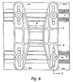
- the supporting body has the shape of an approximately rectangular plate, which on one flat side bears the bearing surface with the first and the second field of serrations running at right angles to one another.
- the plate-shaped support body has the advantage that it can easily be cast in when concreting the walls and can be fastened to the steel reinforcements of the concrete, for which purpose it can optionally carry corresponding extensions on its back.
- the two fields with serrations in the plate-shaped support body each extend over the entire bearing surface.
- the support body preferably has two elongated holes running parallel to one another and to one of the serrations, while the counterpart, which is designed as a rectangular plate, contains four elongated holes running at right angles to the elongated holes in the support body, two of which are each assigned to an elongated hole in the support body , wherein on one side of each of the elongated holes of the counterpart there is a field with serrations running parallel to the elongated hole and on the other side of each of these elongated holes a field with serrations running perpendicular to the elongated hole, which has the advantage that Counterpart is supported in the immediate vicinity of the fastener, for example a slot screw.
- the support body contains for its attachment at least two but preferably four arc-shaped elongated holes arranged along a circle, through which bolts anchored in the wall pass, the support body on it the back surface opposite the back carries a radial serration on the edge of one of the elongated holes, which cooperates with a radial serration on a flange seated on the associated bolt.
- This allows the support body to rotate within the area delimited by the oval elongated holes.
- the height compensation can take place in that the flange is adjustable in height, for which purpose a sleeve is expediently formed, into which a further sleeve, which is supported on the wall, can be screwed for height adjustment.
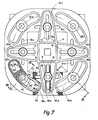
- the counterpart is advantageously designed in the form of a four-armed star, in the arms of which elongated holes are arranged in the arm's longitudinal direction, while the support body has four elongated holes arranged along the edges of a square or rectangle contains, one of which is assigned to an elongated hole in the counterpart and runs at right angles to this respective elongated hole.
- a large adjustment range is obtained if the two fields with serrations on the support body overlap each other, but only in the area of the elongated holes.
- the inclinably adjustable connection contains two wedge-shaped disks which can be rotated relative to one another and lie flat on top of one another between the counterpart and the holding plate, which lie on assigned surfaces of the counterpart and the holding plate and have radial serrations at least on the edge side, with which they are both mutually and with associated radial teeth Serrations are positively engaged in the associated surfaces of the counterpart and the holding plate.
- the connection is held together by a central screw or bolt.
- FIG. 1 an approximately square holding plate 1 is illustrated, the middle of a recognizable in the top view handle 2 for supporting structures, such as cable trays, and at the four corners by means of supporting bodies 3 and counterparts 4 on the wall or the like. of a building is attached.
- the support body 3 which has approximately the shape of a rectangular flat disk, contains in its center an opening 5 for receiving a fastening means in the form of a screw 6 which can be screwed into the wall.
- a fastening means in the form of a screw 6 which can be screwed into the wall.
- the counterpart 4 as shown in FIGS. 1 and 3, has approximately the shape of a circular disk, which is reinforced in the shape of a truncated cone on the underside in its central region and is approximately planar on the upper side.
- the counterpart 4 there is an elongated hole 10 running through the middle, through which the screw 6 passes and bearing surfaces 11 and 12 are provided on both sides thereof.
- the planar contact surfaces 11 and 12 extending next to the elongated hole 10 contain serrations 13 running at right angles to the elongated hole 10 with the same pitch as the serrations 9 of the supporting body 3, so that there is a positive fit between the two components when the supporting body 3 rests on the counterpart 4 Connection results.
- a radial serration 14 is incorporated into the counterpart 4 on the edge side, as is indicated in the counterpart 4 present at the bottom left in FIG. 1 at 14.
- the radial The serration 14 of the counterpart 4 interacts with a corresponding radial serration 15 in the holding plate 1, wherein there is a concentric circular opening 16 within the serration 15, the diameter of which is chosen to be large. that the screw 6 can freely pass through the holding plate 1 in any position within the elongated hole 10.
- the holding plate 1 has on its upper side an annular rim 17 which concentrically surrounds the opening 16 and whose inside diameter is slightly larger than the outside diameter of the counterpart 4. This ensures that the counterpart 16 is concentrically aligned even before the radial serrations 14 and 15 mesh.
- the dowels for a total of four screws 6 are first placed and then the holding plate 1 is fastened to the wall 18 of the building using the counterparts 4, the supporting body 3 and the screws 6.
- a respective holding plate 1 can be moved within the limits defined by the elongated holes 10 before the screws 6 are tightened on the wall.
- the counterparts 4 are also rotatably connected to the holding plate 1, the holding plate 1 can be displaced not only upwards or downwards, but also at any angle, for which purpose the elongated holes 10 of all counterparts 4 are rotated in the corresponding direction before the screws 6 can be tightened.
- the possible adjustment range of the holding plate 1 with respect to the screws 6 results from the length of the elongated holes 10 or the openings 16 in the holding plate 1.
- the fineness of the setting is determined by the division of the serrations 9, 13 and 14, 15 and is the more precise the smaller the division.
- the holding plate 1 remains immovable in place.
- a metal plate 19 can also be embedded or placed in the wall 18 in the area of the holding plate 1.
- all suitable metals, but preferably aluminum alloys, are largely suitable.
- two rail-shaped supporting bodies are fastened in parallel and at a distance from one another on a wall of a building and carry an approximately H-shaped counterpart 4, on the middle leg 20 of which, for example, a handle for a cable platform is attached.
- the support body or bodies 3 consist here of a web 21, on one side of which a longitudinally extending foot 22 and on the other side of which a likewise longitudinally extending head 23 is formed, which runs essentially parallel to the underside of the foot 22 Bearing surfaces 7 and 8 carries.
- bores 25 In the bottom of the groove 24 there are bores 25 extending at a distance from one another through the foot 22, through which the fastening screws screwed into the wall 18 pass, such as the illustrated screw 26, the head of which is located within the groove 24.
- two grooves 28 and 29 extending over the longitudinal direction of the support body 3 are formed below the bearing surfaces 7 and 8 for receiving a clamping means.
- the two otherwise flat bearing surfaces 7 and 8 contain serrations 13, in such a way that the serration 13 in the bearing surface 7 in the direction parallel to the longitudinal extent of the groove 24 or of the supporting body 3 and the serration 13 in the support surface 8 runs perpendicular to the longitudinal extent of the supporting body 3.
- the support surface 7 thus contains a first field with serrations 13, while the support surface 8 contains a second field with serrations 13, which runs at an angle or at right angles to the serration 13 of the first field.
- the counterpart 4 which is approximately H-shaped in its layout, is flat on its side opposite the two support bodies 3 and rests with its outwardly facing arms 30a to 30d on the contact surfaces 7 and 8 of the two support bodies 3.
- each of the arms 30a to 30d there is an elongated hole 31 which runs at right angles to the longitudinal extent of the support body 3 and serves to receive a clamping means 32.
- the underside of the arms 30a to 30d forms the contact surface 33 of the counterpart 4 which cooperates with the contact surfaces 7 and 8 of the support body 3, two serrations 13a and 13b running at right angles to one another being provided in the contact surface 33, so that this is shown in FIG. 6 shows the illustrated pattern on the bearing surface 33, which forms a large number of pyramids or truncated pyramids arranged in rows and columns with a square base when the serrations 13a and 13b are orthogonal.
- the serrations 9 are provided in two fields which do not overlap each other in the contact surfaces 7 and 8 of the support body 3, the two fields of the serrations 13a and 13b lie one above the other in the contact surface 33.
- the clamping means 32 for fastening the counterpart 4 on the supporting bodies 3 consists of a nut 34 seated in the grooves 28, 29 and secured against rotation, a washer 35 resting on the flat top of the counterpart 4 in the area of the elongated holes 31 and a through the washer 35 and through the elongated hole 31 into the groove 24 and screwed into the nut 34 screw 36. It can be seen that each of the arms 30a to 30d is screwed to the associated support body 3 with a clamping means 32 constructed in this way .
- a supporting structure attached to the counterpart 4 can not only be displaced with respect to the wall on which the device is located, but also rotated.
- the support body 3 consists of an approximately square plate to which. stiffening ribs or edges pointing towards the wall of the building can be formed for reinforcement.
- the on Its top surface which is largely flat, has a total of four oval elongated holes 40a to 40d provided on a circle, through which screws or bolts 41 which can be screwed into the wall of the building extend as fastening means for the support body 3.
- the screw or the bolt 41 can be countersunk in the case of a support body 3 with stiffening ribs, in that a deep-drawn shoulder 42 following the contour of the elongated hole is formed in each elongated hole 40a to 40d, on the corresponding washer. 43 rests, whereby the support body 3 can be screwed to the wall.
- the support body 3 has on its side facing the wall a radial serration 44 which is arranged around the elongated hole 40a.
- the radial serration 44 is oriented so that it converges towards the center of the circle on which the elongated holes 40a to 40d are arranged.
- a flange 45 On the screw 41 assigned to the elongated hole 40a there is a flange 45 which on its upper side, which faces the underside of the support piece 3, carries a radial serration 46 corresponding to the radial serration 44 and is thus in engagement with the serration 44.
- an upwardly projecting sleeve 48 with an internal thread 49 is formed, into which a sleeve 50 with a corresponding external thread 51 can be screwed more or less deeply.
- the sleeve 50 is directly on the shaft of the screw 41.
- the sleeve 48 In its upper region, the sleeve 48 is tapered at 52 and carries at its uppermost end a thread 53 consisting of only a few thread turns, against which a cylindrically smooth part with a diameter smaller than or equal to the core diameter of the thread is directed towards the flange 45 53 connects.
- the thread 53 together with the cylindrically smooth part 52 serves to hold the flange 45 captively on the elongated hole 40a, for which purpose the washer 43a located in this elongated hole carries on its underside a cylindrical extension 54 which has a few gears on the thread at its lower end Has 53 screw-on internal thread 55. Between the thread 55 and the underside of the washer 43a there is a cylindrically smooth section in which the threads of the thread 53 are freely displaceable. The clearance, the thread has in the axial direction in the cylindrical extension 54 is 53, enough selected to be large so that the serrations 44 and 46 may disengage to the flange 45 along the long hole 40a to: move.
- extensions 56a to 56d which engage in the elongated hole 40a and are formed on the flanks of the elongated hole are formed on the upper side of the flange 45 Put on 40a and slide along while adjusting.
- Elongated holes 60a to 60d which are arranged on the edges of a square and serve to accommodate clamping means for the counterpart 4.
- the area 61 located around the elongated holes 60a to 60d forms the bearing surface for the counterpart 4 and contains two serrations 9a and 9b which run at right angles to one another, so that the surface 61 in the area 61 results in a waffle-like pattern, as shown in FIG 6 of the contact surface 33 is present.
- the counterpart 4 has the shape of a four-armed star in FIG. 7, the arms 62a to 62d of which are flat on the underside and rest on the contact surfaces 61.
- each of the arms 62a to 62d there is an elongated hole 63a to 63d, which extends at right angles to the respectively associated elongated hole 60a to 60d of the support body 3 and in which a clamping means 32 extending through the counterpart 4 and the support body 3, for example in FIG The shape of a screw.
- the support surfaces 11 and 12 which cooperate with the support surfaces 61 and which, because they are not visible in FIG. 7, are shown in dashed lines because they are not visible in FIG.
- the bearing surface 11 contains a serration 13a running in the direction parallel to the elongated hole 63a, while the bearing surface 12 has a serration 13b oriented at right angles to the longitudinal extent of the elongated hole 63a.
- the serrations 9a, 9b or 13a, 13b of the bearing surfaces 61 or 11 and 12 are in positive engagement with one another, as in the previous exemplary embodiments, but permit very good engagement with the clamping means released Extensive adjustment of the counterpart 4 relative to the support body 3, limited only by the length of the elongated holes 60a to 60d or 63a to 63d.
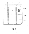
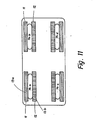
- FIGS. 11 and 12 an embodiment of a fastening device is shown, in which the support body 3 is provided for pouring into the concrete wall of a building.
- a circumferential strip 70 is formed on the edge of the approximately rectangular support body 3 and extends into the concrete wall to the rear.
- On the back of the support body 3 there are fastening devices, not shown, with which the support body 3 is anchored to the steel reinforcement of the concrete wall.
- the front of the support body 3 forms the support surface 7 for the counterpart 4 shown in FIGS. 11 and 12 and contains two serrations arranged orthogonally to one another, as is indicated in detail at 71.
- Two parallel elongated holes 72 and 73 spaced apart from one another, are provided in the support surface 7 for receiving fastening or clamping screws.
- the counterpart 4 also has the shape of a rectangle from the base area and contains four elongated holes 74a to 74d, which are arranged in pairs in relation to one another and which run in pairs and at a distance from one another and, when assembled, extend at right angles to the elongated holes 72 and 73 of the support body 3.
- each of the elongated holes 74a to 74d has a contact surface with a serration in the direction parallel to the longitudinal extent of the elongated hole 74a and a contact surface with a serration at right angles. has the longitudinal extent of the elongated hole 74a.
- the support surfaces 11 and 12 actually engage with the support surface 7 of the support body without play.
- a holding plate 80 can be tiltably connected to the counterpart 4.
- two projections 81 and 82 projecting at right angles are formed, which are inserted into corresponding openings in the holding plate 80 and prevent rotation of the counterpart 4 relative to the holding plate 80.
- two circular wedge-shaped disks 83 and 84 are formed between the back of the counterpart 4 and the holding plate 80, which in their center have two coaxial, deep-drawn cylindrical sections 85 and 86, the cylindrical section 86 being mounted in a corresponding opening 87 in the holding plate 80 .
- Each of the washers has radial serrations 88 and 89 on its top and bottom sides.
- the serration 88 of the disk 83 located on the upper side engages with the serration 89 located on the underside of the disk 84.
- the serration 88 located on the upper side of the disk 84 is in turn engaged with a corresponding radial serration 90 in the holding plate 80, while the serration 89 of the disk 83 engages in a suitable serration 91 on the rear side of the counterpart 4.
- clamping element 4 the two disks 83 and 84 and the holding plate 80 are braced against one another by clamping means, which are not illustrated in any more detail.
- the degree of inclination of the holding plate 80 relative to the counterpart 4 can be determined according to the angle of rotation of the two disks relative to one another, while the simultaneous rotation of the two wedge-shaped disks 83 and 84 set relative to one another determines the direction of the inclination which the counterpart 4 occupies with respect to the holding plate 80.
Landscapes
- Engineering & Computer Science (AREA)
- Architecture (AREA)
- Civil Engineering (AREA)
- Structural Engineering (AREA)
- Physics & Mathematics (AREA)
- Electromagnetism (AREA)
- Clamps And Clips (AREA)
- Connection Of Plates (AREA)
- Building Environments (AREA)
Applications Claiming Priority (2)
| Application Number | Priority Date | Filing Date | Title |
|---|---|---|---|
| DE19823231685 DE3231685A1 (de) | 1982-08-26 | 1982-08-26 | Einstellbare befestigungsvorrichtung fuer tragkonstruktionen |
| DE3231685 | 1982-08-26 |
Publications (2)
| Publication Number | Publication Date |
|---|---|
| EP0101984A2 true EP0101984A2 (fr) | 1984-03-07 |
| EP0101984A3 EP0101984A3 (fr) | 1985-01-23 |
Family
ID=6171689
Family Applications (1)
| Application Number | Title | Priority Date | Filing Date |
|---|---|---|---|
| EP83107717A Withdrawn EP0101984A3 (fr) | 1982-08-26 | 1983-08-05 | Dispositif d'attache ajustable pour construction de soutien |
Country Status (2)
| Country | Link |
|---|---|
| EP (1) | EP0101984A3 (fr) |
| DE (1) | DE3231685A1 (fr) |
Cited By (6)
| Publication number | Priority date | Publication date | Assignee | Title |
|---|---|---|---|---|
| EP0322039A1 (fr) * | 1987-12-21 | 1989-06-28 | Gelmer Karl Wichers | Bloc d'ancrage |
| WO1990012939A1 (fr) * | 1989-04-27 | 1990-11-01 | David Arthur Coe | Socle de nivellement et positionnement |
| GB2247703A (en) * | 1989-04-27 | 1992-03-11 | David Arthur Coe | Positioning and levelling base |
| US6434368B1 (en) | 1998-10-27 | 2002-08-13 | Telefonaktiebolaget Lm Ericsson (Publ) | Diode-based switch for a radio transceiver |
| US7213376B2 (en) | 2000-10-18 | 2007-05-08 | Teraspeikko Oy | Bracket for supporting structural element to support structure |
| CN108360906A (zh) * | 2018-01-23 | 2018-08-03 | 倪惠芳 | 一种航空航天用塔架加固装置 |
Families Citing this family (3)
| Publication number | Priority date | Publication date | Assignee | Title |
|---|---|---|---|---|
| DE3842229C2 (de) * | 1988-12-15 | 1995-09-07 | Stefan Wolfgang | Befestigungsvorrichtung für einen an einer Stahlbetondecke festgelegten Hängestiel |
| DE20106025U1 (de) | 2001-04-06 | 2001-06-28 | Waidelich, Hans, 72226 Simmersfeld | Verankerungselement zur Verankerung von Bauelementen |
| DE20218663U1 (de) | 2002-12-02 | 2003-03-06 | Rothschild, Angelica, 52064 Aachen | Befestigungselement für Gegenstände bei vorhandenen Dübellöchern, ohne neue Löcher zu bohren |
Family Cites Families (2)
| Publication number | Priority date | Publication date | Assignee | Title |
|---|---|---|---|---|
| US1628550A (en) * | 1926-12-03 | 1927-05-10 | James O Meredith | Anchoring device |
| DE2716288B1 (de) * | 1977-04-13 | 1978-11-02 | Ruhrchemie Ag, 4200 Oberhausen | Verfahren zur Herstellung von 23-Dimethylpentanal |
-
1982
- 1982-08-26 DE DE19823231685 patent/DE3231685A1/de not_active Withdrawn
-
1983
- 1983-08-05 EP EP83107717A patent/EP0101984A3/fr not_active Withdrawn
Cited By (8)
| Publication number | Priority date | Publication date | Assignee | Title |
|---|---|---|---|---|
| EP0322039A1 (fr) * | 1987-12-21 | 1989-06-28 | Gelmer Karl Wichers | Bloc d'ancrage |
| WO1990012939A1 (fr) * | 1989-04-27 | 1990-11-01 | David Arthur Coe | Socle de nivellement et positionnement |
| GB2247703A (en) * | 1989-04-27 | 1992-03-11 | David Arthur Coe | Positioning and levelling base |
| GB2247703B (en) * | 1989-04-27 | 1993-08-18 | David Arthur Coe | Positioning and levelling base |
| US6434368B1 (en) | 1998-10-27 | 2002-08-13 | Telefonaktiebolaget Lm Ericsson (Publ) | Diode-based switch for a radio transceiver |
| US7213376B2 (en) | 2000-10-18 | 2007-05-08 | Teraspeikko Oy | Bracket for supporting structural element to support structure |
| CN108360906A (zh) * | 2018-01-23 | 2018-08-03 | 倪惠芳 | 一种航空航天用塔架加固装置 |
| CN108360906B (zh) * | 2018-01-23 | 2019-11-15 | 倪惠芳 | 一种航空航天用塔架加固装置 |
Also Published As
| Publication number | Publication date |
|---|---|
| EP0101984A3 (fr) | 1985-01-23 |
| DE3231685A1 (de) | 1984-03-01 |
Similar Documents
| Publication | Publication Date | Title |
|---|---|---|
| DE3701530A1 (de) | Gezahnte ankerschiene | |
| DE102012021566B3 (de) | Zentriereinrichtung | |
| EP1317631A1 (fr) | Piece de liaison pour rails de montage | |
| DE2227593C2 (de) | Anordnung zur Befestigung des einen Laufrings eines Drehkranzes eines Krans | |
| EP0101984A2 (fr) | Dispositif d'attache ajustable pour construction de soutien | |
| WO2017207263A1 (fr) | Module de support vertical pour tour d'échafaudage pour charges lourdes | |
| WO1985003731A1 (fr) | Installation de fixation au sol | |
| EP0787511A1 (fr) | Elément de support, notamment plaque d'attache, pour arrêter de fixations sur de surf des neiges ou analogues | |
| EP0496975B1 (fr) | Elément de raccordement | |
| DE3841281C2 (fr) | ||
| DE3913984A1 (de) | Stuetze fuer einen doppelboden | |
| DE2238296C3 (de) | Rollfläche bildende Anordnung | |
| EP1247922B1 (fr) | Support de sol avec une plaque de tête pour supporter une structure de faux plancher surélevé et structure de faux plancher surélevé | |
| EP0152530B1 (fr) | Dispositif de fixation au sol | |
| EP0566829A1 (fr) | Console d'appui pour blocs de construction, plaques de parement ou similaires | |
| DE202005002790U1 (de) | Bausatz zur Verbindung von Trägerelementen | |
| AT521341B1 (de) | Montagevorrichtung für einen Rammpfahl | |
| EP0607462B1 (fr) | Faux plancher surélevé | |
| EP3091268A1 (fr) | Dispositif d'alignement de moteurs, de machines et de pieces de machines | |
| EP4545720B1 (fr) | Agencement d'un corps creux de liaison d'angle d'une cellule spatiale et d'un dispositif de fixation et procédé de montage du dispositif de fixation sur le corps creux de liaison d'angle | |
| DE60308807T2 (de) | Vorrichtung und Verfahren für die Festlegung eines Kalibers auf einem Gehäusering | |
| DE2941718A1 (de) | Verbindungsvorrichtung fuer gitterstrukturen | |
| DE202018106923U1 (de) | Vorrichtung zum Befestigen von Schieferplatten auf einem Befestigungsbock und Schiefer, der diese Vorrichtung umfasst | |
| EP3144445A1 (fr) | Système d'appui de palier, système d'appui, console | |
| DE4201152C1 (en) | Edge support for flat elements - has wall mounted strap with orthogonally protruding cylindrical set bolt with annular groove |
Legal Events
| Date | Code | Title | Description |
|---|---|---|---|
| PUAI | Public reference made under article 153(3) epc to a published international application that has entered the european phase |
Free format text: ORIGINAL CODE: 0009012 |
|
| AK | Designated contracting states |
Designated state(s): BE CH FR GB LI |
|
| PUAL | Search report despatched |
Free format text: ORIGINAL CODE: 0009013 |
|
| AK | Designated contracting states |
Designated state(s): BE CH FR GB LI |
|
| 17P | Request for examination filed |
Effective date: 19850425 |
|
| STAA | Information on the status of an ep patent application or granted ep patent |
Free format text: STATUS: THE APPLICATION IS DEEMED TO BE WITHDRAWN |
|
| 18D | Application deemed to be withdrawn |
Effective date: 19860228 |
|
| RIN1 | Information on inventor provided before grant (corrected) |
Inventor name: GRUENERT, ALFRED, DIPL.-ING. |