EP0102021A2 - Reissverschluss mit automatischem unterem Endstopp - Google Patents
Reissverschluss mit automatischem unterem Endstopp Download PDFInfo
- Publication number
- EP0102021A2 EP0102021A2 EP83108041A EP83108041A EP0102021A2 EP 0102021 A2 EP0102021 A2 EP 0102021A2 EP 83108041 A EP83108041 A EP 83108041A EP 83108041 A EP83108041 A EP 83108041A EP 0102021 A2 EP0102021 A2 EP 0102021A2
- Authority
- EP
- European Patent Office
- Prior art keywords
- coupling
- closure
- slider
- coupling elements
- fixed
- Prior art date
- Legal status (The legal status is an assumption and is not a legal conclusion. Google has not performed a legal analysis and makes no representation as to the accuracy of the status listed.)
- Withdrawn
Links
Images
Classifications
-
- A—HUMAN NECESSITIES
- A44—HABERDASHERY; JEWELLERY
- A44B—BUTTONS, PINS, BUCKLES, SLIDE FASTENERS, OR THE LIKE
- A44B19/00—Slide fasteners
- A44B19/24—Details
- A44B19/36—Means for permanently uniting the stringers at the end; Means for stopping movement of slider at the end
-
- A—HUMAN NECESSITIES
- A44—HABERDASHERY; JEWELLERY
- A44B—BUTTONS, PINS, BUCKLES, SLIDE FASTENERS, OR THE LIKE
- A44B19/00—Slide fasteners
- A44B19/24—Details
- A44B19/38—Means at the end of stringer by which the slider can be freed from one stringer, e.g. stringers can be completely separated from each other
Definitions
- the present invention relates to a zipper with automatic lower stop.
- automatic lower stop is meant a stop formed by a male part and a female part fixed, respectively, to the edge of one and the other of the support ribbons each carrying, at its inner edge, a row of coupling elements and forming one half of the closure.
- the two parts of the stopper are fixed to the support bands at the same time as the coupling elements, for example by injection, and are shaped so that they can be coupled by the slider, when placing it by the lower end of the two closure halves.
- An automatic lower stop therefore has the advantage, compared to a non-automatic stop, that is to say a stop fixed after the positioning of the slider, to allow the simultaneous molding of all the elements of the closure as well as finishing operations (calibration, brushing, galvanic treatment, enameling, etc.) without being hindered by the presence of the cursor.
- An automatic lower stop closure is the subject of patent 580 403.
- This closure comprises an automatic lower stop formed by a male part, a female part and a cleat fixed after one of these two parts.
- this cleat has the shape of an oblique, oblong parallelepiped comprising two opposite non-rectangular faces. It is fixed to the edge of the support tape so that these faces and its base are substantially perpendicular to the plane of the support tape and therefore to the plane of the closure.
- the lower edge of the cleat which connects the acute angles of its non-rectangular faces, is blunted so that the cleat has, at its lower end, a chamfer.
- the cleat can be oriented relative to the guide channel of the cursor, so that the latter can be introduced by the lower end of the two halves of the closure and moved upwards. During this movement, it prints on the two support ribbons, and consequently on the male and female parts of the lower stop, a rotational movement towards one another, around the lower ends of the ribbons, therefore causes them to be coupled .
- the automatic lower stop described above has the advantage of being able to be applied to both a separable closure and an inseparable closure.
- the cleat In the first case, the cleat must be fixed after the female part at a distance such that the corner of the slider penetrates between the male and female parts before the cusor abuts against the cleat.
- the cleat In this second case, the cleat must be fixed after the male part at a distance such that the slider abuts against the cleat before its corner can reach the male and female parts.
- the object of the present invention is to obviate the aforementioned drawback of the automatic lower stop closure described above.
- a zipper with automatic lower stop comprising two halves formed each of a support tape carrying, at its inner edge, a row of coupling elements, a slider whose displacement in one or the other direction causes the coupling, respectively the uncoupling of the two rows of coupling elements, and an automatic lower stop formed by a male part and a female part fixed, respectively, at the edge of one and the other of the support tapes and shaped so as to be able to be coupled by the cursor; when it is in place, and a cleat fixed after one of the two parts, at a distance from it, and having the shape of an oblique parallelepiped and a dull lower edge, so as to be able to engage and pass through the slider channel, during the positioning of the latter, characterized in that the width of the head of the male part, intended to engage in a cavity in the female part, when the two parts are coupled, is at least 1.5 times larger than the l headiness of the coupling elements.
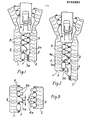
- Closing the lower part is shown in fig.l and 2 comprises, in known manner, two halves each formed from a carrier tape 1 and 2 p res ectively, carrying at its inner edge a row of elements coupling 3 and 4 respectively.
- the closure is provided with an automatic lower stop of the type described above, that is to say a stop comprising a male part 5, fixed to the edge of the support tape l, following the last coupling element 3, a part fe melle 6, fixed to the edge of the support tape 2, following the last coupling element 4, and a cleat 7 fixed to the edge of the support tape l, at a certain distance from the male part 5.
- the closure is provided with a slider 8 whose displacement up and down causes the coupling, respectively the uncoupling of the two rows of coupling elements and consequently the closing and the opening of the closure.
- the positioning of the slider is made by the lower end of support ribbons 1 and 2, as explained above. This was possible despite the presence of the cleat 7, thanks to the shape of the latter and the flexibility of the support tape (see FIG. 2 of patent 580 403) .
- the positioning of the slider 8 the coupling of the two rows of coupling elements and the formation of the automatic lower stop, by coupling the male 5 and female 6 thanks to the engagement of the head 5a of the first in a cavity 6a of the second, were carried out correctly.
- Fig. 2 Such a case is shown in Fig. 2.
- the slider 8 could be put in place because the spacing of the coupling elements 4 and the bending of the support tape 2 made it possible at the head 5a of the male part 5 to engage between the two coupling elements and thus allow advancement of the cursor 8.
- the width B of the head 5a of the male part 5 is at least one and a half times greater than the width A of the head 4a of the coupling elements 4.
- This minimum ratio of 1.5 is chosen taking into account the difference between two coupling elements, which is determined by the width of their heads, and the possible bending of the support tape, so that the head of the male part cannot engage between two coupling elements.
- the closure according to the present invention cannot be provided with a slider when the lower ends of its two halves are not not aligned, that is to say when the male 5 and female 6 parts are not one opposite the other to be able to be ac - coupled by the cursor.
- the closure shown in Figs. 1 to 3 is a closure that cannot be separated from the fact that the cleat 7 is fixed to the edge of the same support tape 1 as the male part 5.
- the incorrect coupling of such a closure when the place of the cursor 8, can only occur during manufacture.
- incorrect coupling and blocking of the cursor in a separable closure that is to say when the cleat 7 is fixed to the edge of the same tape -support 2 that the female part 6, can occur each time when proceeding to the assembly of the two halves of the closure, which have been completely separated, with their lower ends not aligned.
Landscapes
- Slide Fasteners (AREA)
Applications Claiming Priority (2)
| Application Number | Priority Date | Filing Date | Title |
|---|---|---|---|
| CH5129/82 | 1982-08-30 | ||
| CH512982A CH647938A5 (fr) | 1982-08-30 | 1982-08-30 | Fermeture a glissiere a arret inferieur automatique. |
Publications (2)
| Publication Number | Publication Date |
|---|---|
| EP0102021A2 true EP0102021A2 (de) | 1984-03-07 |
| EP0102021A3 EP0102021A3 (de) | 1984-10-10 |
Family
ID=4288420
Family Applications (1)
| Application Number | Title | Priority Date | Filing Date |
|---|---|---|---|
| EP83108041A Withdrawn EP0102021A3 (de) | 1982-08-30 | 1983-08-13 | Reissverschluss mit automatischem unterem Endstopp |
Country Status (2)
| Country | Link |
|---|---|
| EP (1) | EP0102021A3 (de) |
| CH (1) | CH647938A5 (de) |
Family Cites Families (6)
| Publication number | Priority date | Publication date | Assignee | Title |
|---|---|---|---|---|
| US1949882A (en) * | 1933-02-16 | 1934-03-06 | Rocke Louis | Detachable clasp |
| NL123518C (de) * | 1959-03-09 | |||
| CH580403A5 (de) * | 1974-03-08 | 1976-10-15 | Erde Sa | |
| DE2644965C3 (de) * | 1976-06-23 | 1980-06-04 | Optilon W. Erich Heilmann Gmbh, Cham (Schweiz) | Teilbarer Reißverschluß |
| JPS5925219Y2 (ja) * | 1978-07-31 | 1984-07-25 | ワイケイケイ株式会社 | スライドフアスナ_の下止 |
| JPS5942895Y2 (ja) * | 1980-11-01 | 1984-12-18 | ワイケイケイ株式会社 | 分割型下止具付きスライドフアスナ− |
-
1982
- 1982-08-30 CH CH512982A patent/CH647938A5/fr not_active IP Right Cessation
-
1983
- 1983-08-13 EP EP83108041A patent/EP0102021A3/de not_active Withdrawn
Also Published As
| Publication number | Publication date |
|---|---|
| EP0102021A3 (de) | 1984-10-10 |
| CH647938A5 (fr) | 1985-02-28 |
Similar Documents
| Publication | Publication Date | Title |
|---|---|---|
| EP0150046A2 (de) | Armband für Uhren | |
| LU84217A1 (fr) | Cassette de bande magnetique | |
| FR2501484A1 (fr) | Boucle moulee en matiere plastique | |
| FR2751863A1 (fr) | Support de clips hemostatiques | |
| FR2537761A1 (fr) | Cassette a bande comportant un mecanisme a verrou servant a verrouiller un capot de protection de la bande | |
| FR2503914A1 (fr) | Recipient pour cassette a bande magnetique | |
| FR2798596A1 (fr) | Systeme de retenue d'une fixation, ski correspondant et procede de montage rapide d'une machoire avant et d'une talonniere d'une fixation de ski | |
| EP0075501A1 (de) | Bindestreifen | |
| EP0029042A1 (de) | Reissverschlussschieber mit auf dem zugglied geschobenem teil | |
| EP0229554B1 (de) | Vorrichtung zur Befestigung von Verbindungselementen an einem Förderband oder dergleichen | |
| FR2570937A1 (fr) | Dispositif d'approvisionnement en curseurs de fermetures a glissiere. | |
| FR2533119A1 (fr) | Boucles coulissantes pour relier entre elles deux extremites de bandes | |
| EP0102021A2 (de) | Reissverschluss mit automatischem unterem Endstopp | |
| FR2497080A1 (fr) | Fermeture a glissiere separable | |
| CH675405A5 (de) | ||
| EP0090726A1 (de) | Verbindungsband | |
| FR2539393A1 (fr) | Flan pour la constitution d'un emballage sur lequel doit etre rapportee une poignee, et ebauche d'emballage et emballage correspondants | |
| EP0122427A1 (de) | Reissverschluss mit automatischem unterem Endglied | |
| FR2581353A1 (fr) | Chemise de classement de documents a dos de largeur variable equipee d'une sangle de fermeture | |
| FR2518376A1 (fr) | Dispositif de fermeture d'articles divers, notamment chaussures, vetements ou sacs | |
| FR2471332A1 (fr) | Recipient distributeur pour emplatre vulneraire fixe de maniere detachable le long d'une bande | |
| FR2581033A1 (fr) | Emballage en carton, carton ondule ou autre materiau en feuille, et son dispositif de verrouillage | |
| CH654552A5 (fr) | Cassette pour dispositif d'alimentation en feuilles. | |
| FR2493697A1 (fr) | Outil de podologie en forme de gouge a lame amovible et lame pour un tel outil | |
| EP0164790A1 (de) | Verschluss- und Speicherring für Aufzeichnungsbandspule |
Legal Events
| Date | Code | Title | Description |
|---|---|---|---|
| PUAI | Public reference made under article 153(3) epc to a published international application that has entered the european phase |
Free format text: ORIGINAL CODE: 0009012 |
|
| AK | Designated contracting states |
Designated state(s): DE FR IT |
|
| PUAL | Search report despatched |
Free format text: ORIGINAL CODE: 0009013 |
|
| AK | Designated contracting states |
Designated state(s): DE FR IT |
|
| 17P | Request for examination filed |
Effective date: 19841219 |
|
| STAA | Information on the status of an ep patent application or granted ep patent |
Free format text: STATUS: THE APPLICATION IS DEEMED TO BE WITHDRAWN |
|
| 18D | Application deemed to be withdrawn |
Effective date: 19861106 |
|
| RIN1 | Information on inventor provided before grant (corrected) |
Inventor name: SCARPINI, FRANCO |