EP0102099A1 - Vertikal angeordnete Plattenelektrode für gasbildende Elektrolyseure - Google Patents
Vertikal angeordnete Plattenelektrode für gasbildende Elektrolyseure Download PDFInfo
- Publication number
- EP0102099A1 EP0102099A1 EP83201053A EP83201053A EP0102099A1 EP 0102099 A1 EP0102099 A1 EP 0102099A1 EP 83201053 A EP83201053 A EP 83201053A EP 83201053 A EP83201053 A EP 83201053A EP 0102099 A1 EP0102099 A1 EP 0102099A1
- Authority
- EP
- European Patent Office
- Prior art keywords
- electrode
- membrane
- distance
- counter electrode
- degassing
- Prior art date
- Legal status (The legal status is an assumption and is not a legal conclusion. Google has not performed a legal analysis and makes no representation as to the accuracy of the status listed.)
- Granted
Links
Images
Classifications
-
- C—CHEMISTRY; METALLURGY
- C25—ELECTROLYTIC OR ELECTROPHORETIC PROCESSES; APPARATUS THEREFOR
- C25B—ELECTROLYTIC OR ELECTROPHORETIC PROCESSES FOR THE PRODUCTION OF COMPOUNDS OR NON-METALS; APPARATUS THEREFOR
- C25B11/00—Electrodes; Manufacture thereof not otherwise provided for
- C25B11/02—Electrodes; Manufacture thereof not otherwise provided for characterised by shape or form
- C25B11/03—Electrodes; Manufacture thereof not otherwise provided for characterised by shape or form perforated or foraminous
Definitions
- the invention relates to a vertically arranged plate electrode for gas-forming electrolyzers with horizontally divided electrode plates, the upper edges of which are designed as gas discharge elements and face away from the counterelectrode.
- electrodes with openings for the removal of the reaction gases are generally used, for example perforated electrodes, wire mesh, or expanded metal.
- the disadvantages include reduced active surface, lack of stability and loss of high quality coating material on the back of the electrode.
- an electrode plate consisting of individual plates has already been provided for vertically arranged electrodes in gas-forming diaphragm cells, the individual plates having guide surfaces for the discharge of the gas generated. Due to the intended inclination of the guide plate, there are inevitably different distances between the active surface and the counter electrode.
- the electrodes In the known from FR-PS 1028153 E lektrolyseur are arranged, the electrodes with the least possible distance in parallel.
- the previously known electrodes are formed from one or more plates. The plates have horizontal openings, which are caused by bending the plate strips and offer the least resistance to the gas outlet. The bends face away from the counter electrode, there is no noticeable reduction in the active surface.
- a similar type of arrangement of electrodes is also known from DE-PS 453750. In the previously known electrodes, cuts are made, by means of which sections of any shape are bent out, in such a way that they are directed towards the side facing away from the electrode.
- electrodes or cathodes of this type have been known for more than 30 years, they have still not found their way into technical practice. Rather, perforated sheets, expanded metal or similar materials are still used.
- the invention has for its object to provide an electrode which ensures safe and rapid gas removal from the electrolyte with the smallest distance ratio.
- the invention solves this problem with a vertically arranged plate electrode for gas-forming electrolysers, in particular membrane electrolysers, with horizontally divided electrode plates, the entire active electrode surface of which is arranged parallel and at the shortest distance from the counterelectrode and whose respective upper edges are designed as a 'gas discharge element and turned away from the counterelectrode are.
- the invention consists in the fact that the ratio of the distance G between the counter electrode / membrane and the degassing apex S the lower edge of the electrode plate, to the distance E, between the counter electrode / membrane and the tear-off edge K of the angled gas discharge element, corresponds to a value F (degassing capacity) of less than 0.6.
- the angled part of the individual plates of the electrode according to the invention is generally designed as a flat surface, but can also be curved.
- the angle from the electrode plane is generally between 15 and 70 °.
- the individual electrode plate has a height of 5 to 50 cm and a thickness of about 1 to 3 mm in the vertical part. The thickness of the individual electrode plate depends on the width of the electrode, since no additional current distribution bolts are provided, which, for. B. with cells of conventional dimensions and when using expanded metal as an active surface are necessary.
- the electrode plates are firmly installed in a manner known per se in a frame which has connection elements for the supply of the electric current.
- the electrode according to the invention can be used as an anode or cathode in membrane electrolysis processes.
- titanium, tantalum, tungsten or zirconium is selected as the electrode material.
- the electrode is only provided with an activating coating on its surface facing the counterelectrode, in known manner from z.
- the electrode according to the invention can be made of e.g. B. steel or nickel or their alloys.
- the electrode plate according to the invention is used in electrolysers with membranes.
- membrane cells are only to be understood as those cells which have ion-selective membranes, such as perfluorinated cation exchange membranes.
- ion-selective membranes such as perfluorinated cation exchange membranes.
- Such membranes allow the separation of cathodic and anodic products of an electrolysis from one another or from the reactants supplied to the counterelectrode.
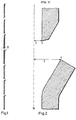
- FIGS. 1 and 2 of the drawing The electrode arrangement according to the invention is illustrated and illustrated by way of example in FIGS. 1 and 2 of the drawing.
- FIG. 1 a side view of an electrode divided into individual plate strips with angled gas discharge elements is shown horizontally (electrode frame and current supply elements are not shown).
- FIG. 2 shows the detail indicated by "A” in FIG.
- M denotes the membrane
- S the degassing vertex on the lower edge of the plate strip
- K the tear-off edge on the angled upper part of the plate strip arranged underneath.
- G is the distance M - S and E is the distance M - K.
- the degassing vertex lies in the plane of the active surface. If the electrode surfaces are not beveled, the degassing vertex is assumed to lie on the center line of the electrode.
- the term degassing ability is based further on the finding that the gas rising from the electrode gap expands to the tear-off edge K, then rises vertically upwards and divides at the apex of the degassing into a part which re-enters the electrode gap and a predominant other part which, according to the invention, steps behind the electrodes.
- a sodium chloride solution with a concentration of 320 g / l was electrolyzed in a technical chlor-alkali electrolysis plant with an ion-selective membrane to produce sodium hydroxide solution, chlorine and hydrogen.
- the current density was 3.1 KA / m 2 and the temperature of the electrolyte was 80 ° C.
- Electrodes according to the invention with heights of the individual plate strips of 14 cm and active areas of approximately 90% of the projected areas were used as cathodes.
- Steel ST 37 was used as the material without activation.
- a comparison was made with conventional expanded metal cathodes of the same material and the same projected active area.
- Dimensionally stable anodes were used as counter electrodes and a perfluorinated ion exchange membrane (trade name Nafion) was used as the selective membrane.
- the plate thickness was 6.5 mm with a strip width of the individual plate of 100 cm.
- the guide element was bent at an angle of 30 °.
- the gap width between the individual plate strips of the cathode was 20 mm and the distance between the cathode and membrane surface was 3 mm.
- the total electrode area was 1 x 1 m 2 .
- the advantages of the electrode plate of the invention can be seen in the fact that the electrode plate can be arranged at the smallest possible distance with a completely active surface parallel to the counter electrode and punctual overheating of the temperature-sensitive membranes can be avoided, the gas formed between the anode and cathode quickly from the area of the active Surface behind the electrode surface is derived. Furthermore, the electrodes can be produced in a simple manner from flat sheet metal without great technical outlay, and the one-sided application of an active surface layer is also possible without difficulty.
Landscapes
- Chemical & Material Sciences (AREA)
- Engineering & Computer Science (AREA)
- Chemical Kinetics & Catalysis (AREA)
- Electrochemistry (AREA)
- Materials Engineering (AREA)
- Metallurgy (AREA)
- Organic Chemistry (AREA)
- Electrodes For Compound Or Non-Metal Manufacture (AREA)
- Electrolytic Production Of Non-Metals, Compounds, Apparatuses Therefor (AREA)
- Inert Electrodes (AREA)
- Catalysts (AREA)
- Treating Waste Gases (AREA)
Abstract
Description
- Die Erfindung betrifft eine vertikal angeordnete Plattenelektrode für gasbildende Elektrolyseure mit horizontal geteilten Elektrodenplatten, deren Oberkanten als Gasableitungsorgane ausgebildet und von der Gegenelektrode abgewandt sind.
- Bei der Durchführung elektrochemischer Prozesse kommt es auf eine gleichmäßige Verteilung des Stroms über die Elektrodenoberfläche an. Die gleichmäßige Verteilung wird durch die Streufähigkeit des Elektrolyten wie auch durch die Homogenität der Elektroden beeinflußt. Die Streufähigkeit ist um so besser, je größer die auf der Gegenelektrode von den Stromlinien beaufschlagte Fläche ist. Zwar kann mangelnde Streufähigkeit durch Vergrößerung des Elektrodenabstandes ausgeglichen werden, doch wird hierdurch der Spannungsabfall der Zelle erhöht. Bei Inhomogenitäten in der Elektrodenoberfläche bewirkt der Stromfluß lokale Verwerfungen. Dem Abstand der Elektrodenplatten, d.h. dem Abstand zwischen Anode und Kathode kommt somit wesentliche Bedeutung zu. Die Einhaltung bzw. Einstellung eines geringen Elektrodenabstands ist in Gase wie Chlor, Sauerstoff, Wasserstoff erzeugenden Membran-Elektrolysezellen mit Schwierigkeiten verbunden. Bei geringem Abstand zwischen den Elektroden können die Gasblasen nicht schnell genug abgeführt werden.
- Die Anwesenheit von Gas im Elektrolyten zwischen den Elektroden setzt dessen elektrische Leitfähigkeit herab und steigert somit den Energieverbrauch. Des weiteren können Mikrostromverwerfungen in der Elektrodenoberfläche auftreten. Darüberhinaus ruft die Gasentwicklung Turbulenzen im Elektrolyten hervor. Eine turbulente Bewegung des Elektrolyten hat den Nachteil, daß die Membran intensiven mechanischen Belastungen ausgesetzt ist. Zur Vermeidung einer beschleunigten Zerstörung der Membran besteht im allgemeinen der Zwang zur Begrenzung der Höhe der Elektroden, zur Einstellung eines erheblichen Abstandes zwischen den Elektroden der Zelle und zur Begrenzung der elektrischen Stromdichte, was gleichzeitig für die energetische Ausbeute der Elektrolysezelle und ihre Produktivität von Nachteil ist.
- Zur Verminderung der Nachteile von Elektrolysezellen mit Membranen und vertikal angeordneten Elektroden werden im allgemeinen Elektroden mit Öffnungen für die Abfuhr der Reaktionsgase verwendet, beispielsweise gelochte Elektroden, Drahtgewebe, oder Streckmetall. Die Nachteile liegen unter anderem in verminderter aktiver Oberfläche, mangelnder Stabilität und Verlust an hochwertigem Beschichtungsmaterial auf der Elektrodenrückseite.
- Nach einem aus DE-AS 2059868 bekannten Vorschlag hat man auch schon bei vertikal anzuordnenden Elektroden in gasbildenden Diaphragmazellen eine aus einzelnen Platten bestehende Elektrodenplatte vorgesehen, wobei die einzelnen Platten Führungsflächen für die Ableitung des erzeugten Gases aufweisen. Auf Grund der vorgesehenen Neigung der Führungsplatte ergeben sich zwangsläufig unterschiedliche Abstände der aktiven Oberfläche zur Gegenelektrode. Bei dem aus FR-PS 1028153 bekannten Elektrolyseur sind die Elektroden mit dem geringst möglichen Abstand parallel angeordnet. Die vorbekannten Elektroden sind aus einer oder mehreren Platten gebildet. Die Platten besitzen horizontale Öffnungen, die durch Abwinkelungen der Plattenstreifen bewirkt sind und dem Gasaustritt den geringsten Widerstand entgegensetzen. Die Abwinkelungen sind der Gegenelektrode abgewandt, eine merkliche Verringerung der aktiven Oberfläche erfolgt nicht. Eine ähnliche Art der Anordnung von Elektroden ist des weiteren auch aus DE-PS 453750 bekannt. In den vorbekannten Elektroden sind Schnitte eingebracht, mittels derer Teilstücke beliebiger Form herausgebogen sind, und zwar derart, daß diese nach der der Elektrode abgewandten Seite gerichtet sind.
- Obwohl derartige Elektroden bzw. Kathoden seit mehr als 30 Jahren bekannt sind, haben sie dennoch keinen Eingang in die technische Praxis gefunden, vielmehr werden noch immer perforierte Bleche, Streckmetall oder ähnliche Materialien verwendet.
- Der Erfindung liegt die Aufgabe zugrunde, eine Elektrode bereitzustellen, die bei geringstem Abstandsverhältnis eine sichere und rasche Gasabfuhr aus dem Elektrolyten gewährleistet.
- Die Erfindung löst diese Aufgabe mit einer vertikal angeordneten Plattenelektrode für gasbildende Elektrolyseure, insbesondere Membran-Elektrolyseure, mit horizontal geteilten Elektrodenplatten, deren gesamte aktive Elektrodenoberfläche parallel und im kürzesten Abstand zur Gegenelektrode angeordnet ist und deren jeweilige Oberkanten als 'Gasableitungsorgan ausgebildet und von der Gegenelektrode abgewandt sind.
- Bei einer Elektrodenanordnung der genannten Art besteht die Erfindung darin, daß das Verhältnis von Abstand G, zwischen Gegenelektrode/Membran und Entgasungsscheitel S der Unterkante der Elektrodenplatte, zum Abstand E, zwischen Gegenelektrode/Membran und Abreißkante K des abgewinkelten Gasableitungsorgans, einem Wert F (Entgasungsfähigkeit) von kleiner als 0,6 entspricht.
- Es wurde gefunden, daß es gerade bei vorgenanntem Verhältnis zu einer besonders wirkungsvollen Entgasung der Elektrolyt/Gas-Suspension und einer Expansion des freigesetzten Gases kommt, und das Gas zum überwiegenden Teil hinter den nächst höher liegenden Elektrodenstreifen gelangt. Auf diese Weise wird der Elektrolysevorgang dieses höher liegenden Elektrodenstreifens nicht oder nicht nennenswert beeinflußt.
- Der abgewinkelte Teil der einzelnen Platten der erfindungsgemäßen Elektrode ist im allgemeinen als ebene Fläche ausgebildet, kann jedoch auch gewölbt sein. Die Abwinkelung aus der Elektrodenebene liegt im allgemeinen zwischen 15 und 70 °. Die einzelne Elektrodenplatte hat im senkrechten Teil eine Höhe von 5 bis 50 cm bei einer Dicke von etwa 1 bis 3 mm. Die Dicke der einzelnen Elektrodenplatte richtet sich nach der Breite der Elektrode, da keine zusätzlichen Stromverteilungsbolzen vorgesehen sind, die z. B. bei Zellen üblicher Dimensionierung und bei Verwendung von Streckmetall als Aktivfläche notwendig sind.
- Die Elektrodenplatten werden in an sich bekannter Weise fest in einen Rahmen eingebaut, der Anschlußorgane für die Zufuhr des elektrischen Stromes besitzt.
- Die Elektrode gemäß der Erfindung kann als Anode oder Kathode in Membran-Elektrolyseprozessen eingesetzt werden. Bei anodischem Einsatz wird als Elektrodenwerkstoff Titan, Tantal, Wolfram oder Zirconium gewählt. Dabei wird die Elektrode nur auf ihrer der Gegenelektrode zuzuwendenden Oberfläche mit einem aktivierenden Überzug versehen, in bekannter Weise aus z. B. Metalloxiden und Metallen der Gruppe Platin, Iridium, Osmium, Palladium, Rhodium, Ruthenium. In Fällen des Einsatzes der erfindungsgemäßen Elektrode als Kathode in Membran-Elektrolyse-Prozessen kann die Elektrode aus z. B. Stahl oder Nickel oder deren Legierungen bestehen.
- Die erfindungsgemäße Elektrodenplatte wird in Elektrolyseuren mit Membranen eingesetzt. Im Sinne der Erfindung sind unter Membranzellen nur solche Zellen zu verstehen, die ionenselektive Membranen besitzen, wie perfluorierte Kationenaustauscher-Membranen. Derartige Membranen erlauben die Trennung kathodischer und anodischer Produkte einer Elektrolyse voneinander oder von den der Gegenelektrode zugeführten Reaktanden.
- In den Figuren 1 und 2 der Zeichnung ist die erfindungsgemäße Elektrodenanordnung verdeutlicht und beispielhaft dargestellt. In Figur 1 ist in Seitenansicht horizontal eine in einzelne Plattenstreifen geteilte Elektrode mit abgewinkelten Gasableitungsorganen dargestellt (Elektrodenrahmen und Stromzuführungsorgane sind nicht dargestellt).
- In Figur 2 ist das in Figur mit "A" angegebene Detail näher herausgestellt. In Figur 2 bezeichnet M die Membran, S den Entgasungsscheitel an der Unterkante des Plattenstreifens, K die Abrißkante an dem abgewinkelten oberen Teil des darunter angeordneten Plattenstreifens. Mit G ist der Abstand M - S und mit E der Abstand M - K bezeichnet.
- In Fig. 2 mit dargestelltem abgeschrägtem Elektrodenblech liegt'der Entgasungsscheitel in der Ebene der aktiven Oberfläche. Bei nicht abgeschrägten Elektrodenflächen wird der Entgasungsscheitel auf der Mittellinie der Elektrode liegend angenommen. Der Begriff Entgasungsfähigkeit beruhe weiterhin auf der Feststellung, daß das aus dem Elektrodenspalt aufsteigende Gas bis zur Abrißkante K expandiert, dann senkrecht nach oben steigt und sich am Entgasungsscheitel teilt in einen Teil, der wieder in den Elektrodenspalt eintritt und einen überwiegenden anderen, der erfindungsgemäß hinter die Elektroden tritt.
- In einer technischen Chloralkali-Elektrolyse-Anlage mit ionenselektiver Membran zur Erzeugung von Natronlauge, Chlor und Wasserstoff wurde eine Natriumchloridlösung einer Konzentration von 320 g/1 elektrolysiert. Die Stromdichte betrug 3,1 KA/m2 und die Temperatur des Elektrolyten 80 °C.
- Es wurden erfindungsgemäße Elektroden mit Höhen der einzelnen Plattenstreifen von 14 cm und Aktivflächen von ca. 90 % der projizierten Flächen als Kathoden eingesetzt. Als Werkstoff diente Stahl ST 37 ohne Aktivierung. Ferner wurde mit üblichen Streckmetall-Kathoden gleichen Materials und gleicher projizierter Aktivfläche verglichen. Als Gegenelektroden wurden dimensionsstabile Anoden und als selektive Membran eine perfluorierte Ionenaustauschermembran (Handelsnamen Nafion) verwendet. Die Plattendicke betrug 6,5 mm bei einer Streifenbreite der einzelnen Platte von 100 cm. Das Führungsorgan war in einem Winkel von 30 ° abgekantet. Die Spaltbreite zwischen den einzelnen Plattenstreifen der Kathode betrug 20 mm und der Abstand zwischen Kathoden- und Membranfläche 3 mm. Die Gesamtelektrodenfläche belief sich auf 1 x 1 m2.
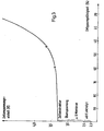
- Hierbei wurde folgender Spannungsabfall (Volt) gemessen:

- Bezeichnet man den Abstand M - S (s. Fig. 2) mit G und den Abstand M - K mit E (Expansionsraum), so ergibt sich die " Expansionsfähigkeit F (%) aus dem Verhältnis von G zu E

- Konstruiert man nun mit den rechenbaren Werten Entgasungsfähigkeit 100 % und Entgasungsfähigkeit 0 % eine Kurve, so liegen die gemessenen Punkte auf der Kurve des Diagramms in Fig. 3, worin der Spannungsabfall gegen die Entgasungsfähigkeit aufgetragen ist.
- Die Vorteile der Elektrodenplatte der Erfindung sind darin zu sehen, daß die Elektrodenplatte in geringst möglichem Abstand mit zur Gegenelektrode paralleler völlig aktiver Oberfläche angeordnet werden kann und punktuelle Uberhitzungen der temperaturempfinglichen Membranen vermieden werden, das zwischen Anode und Kathode gebildete Gas rasch aus dem Bereich der aktiven Oberfläche hinter die Elektrodenfläche abgeleitet wird. Ferner lassen sich die Elektroden auf einfache Weise ohne größeren technischen Aufwand aus Flachblech herstellen wie auch die einseitige Aufbringung einer aktiven Oberflächenschicht ohne Schwierigkeiten möglich ist.
Claims (2)
Priority Applications (1)
| Application Number | Priority Date | Filing Date | Title |
|---|---|---|---|
| AT83201053T ATE30343T1 (de) | 1982-08-03 | 1983-07-16 | Vertikal angeordnete plattenelektrode fuer gasbildende elektrolyseure. |
Applications Claiming Priority (2)
| Application Number | Priority Date | Filing Date | Title |
|---|---|---|---|
| DE3228884 | 1982-08-03 | ||
| DE19823228884 DE3228884A1 (de) | 1982-08-03 | 1982-08-03 | Vertikal angeordnete plattenelektrode fuer gasbildende elektrolyseure |
Publications (2)
| Publication Number | Publication Date |
|---|---|
| EP0102099A1 true EP0102099A1 (de) | 1984-03-07 |
| EP0102099B1 EP0102099B1 (de) | 1987-10-21 |
Family
ID=6169972
Family Applications (1)
| Application Number | Title | Priority Date | Filing Date |
|---|---|---|---|
| EP83201053A Expired EP0102099B1 (de) | 1982-08-03 | 1983-07-16 | Vertikal angeordnete Plattenelektrode für gasbildende Elektrolyseure |
Country Status (11)
| Country | Link |
|---|---|
| US (1) | US4474612A (de) |
| EP (1) | EP0102099B1 (de) |
| JP (1) | JPH062959B2 (de) |
| AT (1) | ATE30343T1 (de) |
| BR (1) | BR8304151A (de) |
| CA (1) | CA1228571A (de) |
| DE (2) | DE3228884A1 (de) |
| ES (1) | ES284413Y (de) |
| IN (1) | IN157978B (de) |
| MX (1) | MX153006A (de) |
| ZA (1) | ZA835568B (de) |
Cited By (1)
| Publication number | Priority date | Publication date | Assignee | Title |
|---|---|---|---|---|
| EP0776996A1 (de) | 1995-11-22 | 1997-06-04 | De Nora S.P.A. | Elektrode für Membran-Elektrolysezellen |
Families Citing this family (13)
| Publication number | Priority date | Publication date | Assignee | Title |
|---|---|---|---|---|
| DE3640584A1 (de) * | 1986-11-27 | 1988-06-09 | Metallgesellschaft Ag | Elektrodenanordnung fuer gasbildende elektrolyseure mit vertikal angeordneten plattenelektroden |
| DE3808495A1 (de) * | 1988-03-15 | 1989-09-28 | Metallgesellschaft Ag | Membranelektrolysevorrichtung |
| DE4224492C1 (de) * | 1992-07-24 | 1993-12-09 | Uhde Gmbh | Vorrichtung zum elektrolytischen Behandeln von Flüssigkeiten mit einer Anoden- und einer Kathodenkammer sowie deren Verwendung |
| DE4306889C1 (de) * | 1993-03-05 | 1994-08-18 | Heraeus Elektrochemie | Elektrodenanordnung für gasbildende elektrolytische Prozesse in Membran-Zellen und deren Verwendung |
| DE4438124A1 (de) * | 1994-10-27 | 1996-05-02 | Eilenburger Elektrolyse & Umwelttechnik Gmbh | Gas-Lift-Elektrolyse- und Reaktionssysteme zur Herstellung von Produkten und zur Anwendung in der Umwelttechnik |
| DE19816334A1 (de) * | 1998-04-11 | 1999-10-14 | Krupp Uhde Gmbh | Elektrolyseapparat zur Herstellung von Halogengasen |
| CA2349508C (en) * | 2001-06-04 | 2004-06-29 | Global Tech Environmental Products Inc. | Electrolysis cell and internal combustion engine kit comprising the same |
| CA2597068A1 (en) * | 2007-06-19 | 2008-12-19 | Peter Romaniuk | Hydrogen/oxygen gas produced by electrolysis as a partial hybrid fuel source for conventional internal combustion engines |
| US9222178B2 (en) | 2013-01-22 | 2015-12-29 | GTA, Inc. | Electrolyzer |
| US8808512B2 (en) | 2013-01-22 | 2014-08-19 | GTA, Inc. | Electrolyzer apparatus and method of making it |
| CN107473336A (zh) * | 2017-09-20 | 2017-12-15 | 合肥齐兴电器有限责任公司 | 一种便携式电解水器 |
| DE102023122813A1 (de) * | 2023-08-24 | 2025-02-27 | Ks Gleitlager Gmbh | Substrat für den Einsatz als Elektrode in einer Elektrolysezelle |
| FR3152519B1 (fr) * | 2023-09-01 | 2025-09-19 | Univ Rennes | cellule élémentaire pour l’électrolyse d’une solution électrolytique produisant des gaz |
Citations (3)
| Publication number | Priority date | Publication date | Assignee | Title |
|---|---|---|---|---|
| FR811238A (fr) * | 1936-09-24 | 1937-04-09 | Perfectionnements apportés aux électrolyseurs | |
| FR1028153A (fr) * | 1949-11-03 | 1953-05-20 | Montedison Spa | électrode pour électrolyseurs bipolaires |
| FR2070757A1 (de) * | 1969-12-06 | 1971-09-17 | Nippon Soda Co |
Family Cites Families (5)
| Publication number | Priority date | Publication date | Assignee | Title |
|---|---|---|---|---|
| DE453750C (de) * | 1927-12-14 | I G Farbenindustrie Akt Ges | Elektrolysierzelle | |
| US1771091A (en) * | 1924-09-01 | 1930-07-22 | Firm Lawaczeck Gmbh | Electrolytic cell |
| GB1595183A (en) * | 1977-03-04 | 1981-08-12 | Ici Ltd | Diaphragm cell |
| US4142950A (en) * | 1977-11-10 | 1979-03-06 | Basf Wyandotte Corporation | Apparatus and process for electrolysis using a cation-permselective membrane and turbulence inducing means |
| JPS57164990A (en) * | 1981-04-03 | 1982-10-09 | Toyo Soda Mfg Co Ltd | Electrolyzing method for aqueous alkali chloride solution |
-
1982
- 1982-08-03 DE DE19823228884 patent/DE3228884A1/de not_active Withdrawn
-
1983
- 1983-07-16 DE DE8383201053T patent/DE3374139D1/de not_active Expired
- 1983-07-16 AT AT83201053T patent/ATE30343T1/de not_active IP Right Cessation
- 1983-07-16 EP EP83201053A patent/EP0102099B1/de not_active Expired
- 1983-07-22 IN IN921/CAL/83A patent/IN157978B/en unknown
- 1983-07-28 ES ES1983284413U patent/ES284413Y/es not_active Expired
- 1983-07-29 ZA ZA835568A patent/ZA835568B/xx unknown
- 1983-08-01 MX MX198252A patent/MX153006A/es unknown
- 1983-08-02 CA CA000433683A patent/CA1228571A/en not_active Expired
- 1983-08-02 BR BR8304151A patent/BR8304151A/pt not_active IP Right Cessation
- 1983-08-03 US US06/520,068 patent/US4474612A/en not_active Expired - Fee Related
- 1983-08-03 JP JP58142386A patent/JPH062959B2/ja not_active Expired - Lifetime
Patent Citations (3)
| Publication number | Priority date | Publication date | Assignee | Title |
|---|---|---|---|---|
| FR811238A (fr) * | 1936-09-24 | 1937-04-09 | Perfectionnements apportés aux électrolyseurs | |
| FR1028153A (fr) * | 1949-11-03 | 1953-05-20 | Montedison Spa | électrode pour électrolyseurs bipolaires |
| FR2070757A1 (de) * | 1969-12-06 | 1971-09-17 | Nippon Soda Co |
Non-Patent Citations (1)
| Title |
|---|
| PATENTS ABSTRACTS OF JAPAN, Band 7, Nr. 7 (C-144)[1152], 12. Januar 1983 & JP - A - 57 164 990 (TOYO SODA KOGYO K.K.) 09-10-1982 * |
Cited By (1)
| Publication number | Priority date | Publication date | Assignee | Title |
|---|---|---|---|---|
| EP0776996A1 (de) | 1995-11-22 | 1997-06-04 | De Nora S.P.A. | Elektrode für Membran-Elektrolysezellen |
Also Published As
| Publication number | Publication date |
|---|---|
| ZA835568B (en) | 1985-03-27 |
| ATE30343T1 (de) | 1987-11-15 |
| IN157978B (de) | 1986-08-09 |
| US4474612B1 (de) | 1989-01-03 |
| EP0102099B1 (de) | 1987-10-21 |
| ES284413Y (es) | 1986-01-16 |
| DE3374139D1 (en) | 1987-11-26 |
| US4474612A (en) | 1984-10-02 |
| ES284413U (es) | 1985-06-01 |
| BR8304151A (pt) | 1984-03-13 |
| JPH062959B2 (ja) | 1994-01-12 |
| DE3228884A1 (de) | 1984-02-09 |
| JPS5943885A (ja) | 1984-03-12 |
| MX153006A (es) | 1986-07-16 |
| CA1228571A (en) | 1987-10-27 |
Similar Documents
| Publication | Publication Date | Title |
|---|---|---|
| EP0102099B1 (de) | Vertikal angeordnete Plattenelektrode für gasbildende Elektrolyseure | |
| DE2809332C2 (de) | Monopolare Elektrolysezelle in Filterpressenbauweise | |
| DE4306889C1 (de) | Elektrodenanordnung für gasbildende elektrolytische Prozesse in Membran-Zellen und deren Verwendung | |
| DE2656650A1 (de) | Bipolare elektrode fuer eine elektrolysezelle | |
| EP0428171A1 (de) | Elektrolysezelle zur Herstellung von Peroxo- und Perhalogenatverbindungen | |
| DE3420483A1 (de) | Bipolarer elektrolyseapparat mit gasdiffusionskathode | |
| DE2430444A1 (de) | Bipolare elektrolysezellen mit perforierten metallanoden | |
| DE2059868B2 (de) | Vertikal anzuordnende Elektrodenplatte für eine gasbildende Elektrolyse | |
| DE69007205T2 (de) | Rahmen für Elektrolyseur der Filterpressenbauart und monopolarer Elektrolyseur der Filterpressenbauart. | |
| DE2404167C2 (de) | Zelle zur elektrolytischen Gewinnung von Metallen sowie Metallgewinnungsverfahren | |
| EP0274138B1 (de) | Elektrodenanordnung für gasbildende Elektrolyseure mit vertikal angeordneten Plattenelektroden | |
| DE69504745T2 (de) | Elektrolyseur für die Herstellung von Natriumhypochlorit und Chlorat, ausgerüstet mit verbesserten Elektroden | |
| DE10234806A1 (de) | Elektrochemische Zelle | |
| DE2538000B2 (de) | Bipolare Elektrodenkonstruktion für eine membranlose Elektrolysezelle | |
| EP0097991B1 (de) | Membran-Elektrolysezelle mit vertikal angeordneten Elektroden | |
| DE10203689A1 (de) | Kathodischer Stromverteiler für Elektrolysezellen | |
| DE2510396C3 (de) | Verfahren zur Elektrolyse wäßriger Natriumchloridlösungen | |
| DE1417194A1 (de) | Anode fuer Elektrolysezellen | |
| DE2828621A1 (de) | Elektrolysezelle und elektrolyseverfahren | |
| DE2003885B2 (de) | Elektrolysezelle | |
| DE3808495A1 (de) | Membranelektrolysevorrichtung | |
| DE2709093A1 (de) | Elektrode fuer die erzeugung eines gases in einer zelle mit einer membran | |
| DE3123665A1 (de) | Vertikal angeordnete plattenelektrode fuer gasbildende elektrolyseure | |
| EP1453990B1 (de) | Verfahren zur elektrolyse einer wässrigen lösung von alkalimetallchlorid | |
| DE60216430T2 (de) | Anodenkonstruktion für elektrolysezellen mit quecksilberkathode |
Legal Events
| Date | Code | Title | Description |
|---|---|---|---|
| PUAI | Public reference made under article 153(3) epc to a published international application that has entered the european phase |
Free format text: ORIGINAL CODE: 0009012 |
|
| AK | Designated contracting states |
Designated state(s): AT BE CH DE FR GB IT LI NL SE |
|
| 17P | Request for examination filed |
Effective date: 19840824 |
|
| GRAA | (expected) grant |
Free format text: ORIGINAL CODE: 0009210 |
|
| AK | Designated contracting states |
Kind code of ref document: B1 Designated state(s): AT BE CH DE FR GB IT LI SE |
|
| REF | Corresponds to: |
Ref document number: 30343 Country of ref document: AT Date of ref document: 19871115 Kind code of ref document: T |
|
| REF | Corresponds to: |
Ref document number: 3374139 Country of ref document: DE Date of ref document: 19871126 |
|
| ET | Fr: translation filed | ||
| ITF | It: translation for a ep patent filed | ||
| GBT | Gb: translation of ep patent filed (gb section 77(6)(a)/1977) | ||
| PLBE | No opposition filed within time limit |
Free format text: ORIGINAL CODE: 0009261 |
|
| STAA | Information on the status of an ep patent application or granted ep patent |
Free format text: STATUS: NO OPPOSITION FILED WITHIN TIME LIMIT |
|
| 26N | No opposition filed | ||
| ITTA | It: last paid annual fee | ||
| PGFP | Annual fee paid to national office [announced via postgrant information from national office to epo] |
Ref country code: AT Payment date: 19930607 Year of fee payment: 11 |
|
| PGFP | Annual fee paid to national office [announced via postgrant information from national office to epo] |
Ref country code: GB Payment date: 19930705 Year of fee payment: 11 |
|
| PGFP | Annual fee paid to national office [announced via postgrant information from national office to epo] |
Ref country code: DE Payment date: 19930812 Year of fee payment: 11 |
|
| PG25 | Lapsed in a contracting state [announced via postgrant information from national office to epo] |
Ref country code: GB Effective date: 19940716 Ref country code: AT Effective date: 19940716 |
|
| EAL | Se: european patent in force in sweden |
Ref document number: 83201053.2 |
|
| GBPC | Gb: european patent ceased through non-payment of renewal fee |
Effective date: 19940716 |
|
| PG25 | Lapsed in a contracting state [announced via postgrant information from national office to epo] |
Ref country code: DE Effective date: 19950401 |
|
| PGFP | Annual fee paid to national office [announced via postgrant information from national office to epo] |
Ref country code: SE Payment date: 19950609 Year of fee payment: 13 |
|
| PGFP | Annual fee paid to national office [announced via postgrant information from national office to epo] |
Ref country code: FR Payment date: 19950616 Year of fee payment: 13 |
|
| PGFP | Annual fee paid to national office [announced via postgrant information from national office to epo] |
Ref country code: CH Payment date: 19950719 Year of fee payment: 13 |
|
| PGFP | Annual fee paid to national office [announced via postgrant information from national office to epo] |
Ref country code: BE Payment date: 19950727 Year of fee payment: 13 |
|
| PG25 | Lapsed in a contracting state [announced via postgrant information from national office to epo] |
Ref country code: SE Effective date: 19960717 |
|
| PG25 | Lapsed in a contracting state [announced via postgrant information from national office to epo] |
Ref country code: LI Effective date: 19960731 Ref country code: CH Effective date: 19960731 Ref country code: BE Effective date: 19960731 |
|
| BERE | Be: lapsed |
Owner name: METALLGESELLSCHAFT A.G. Effective date: 19960731 |
|
| REG | Reference to a national code |
Ref country code: CH Ref legal event code: PL |
|
| PG25 | Lapsed in a contracting state [announced via postgrant information from national office to epo] |
Ref country code: FR Effective date: 19970328 |
|
| EUG | Se: european patent has lapsed |
Ref document number: 83201053.2 |
|
| REG | Reference to a national code |
Ref country code: FR Ref legal event code: ST |