EP0102123A2 - Grue du type à pantographe avec déplacement horizontal de la charge - Google Patents
Grue du type à pantographe avec déplacement horizontal de la charge Download PDFInfo
- Publication number
- EP0102123A2 EP0102123A2 EP83201213A EP83201213A EP0102123A2 EP 0102123 A2 EP0102123 A2 EP 0102123A2 EP 83201213 A EP83201213 A EP 83201213A EP 83201213 A EP83201213 A EP 83201213A EP 0102123 A2 EP0102123 A2 EP 0102123A2
- Authority
- EP
- European Patent Office
- Prior art keywords
- cab
- crane
- carriage
- link
- backstay
- Prior art date
- Legal status (The legal status is an assumption and is not a legal conclusion. Google has not performed a legal analysis and makes no representation as to the accuracy of the status listed.)
- Granted
Links
Images


Classifications
-
- B—PERFORMING OPERATIONS; TRANSPORTING
- B66—HOISTING; LIFTING; HAULING
- B66C—CRANES; LOAD-ENGAGING ELEMENTS OR DEVICES FOR CRANES, CAPSTANS, WINCHES, OR TACKLES
- B66C13/00—Other constructional features or details
- B66C13/52—Details of compartments for driving engines or motors or of operator's stands or cabins
- B66C13/54—Operator's stands or cabins
Definitions
- the invention relates to a double link level luffing crane comprising a base, a jib including a strut member hinged to the base, a backstay member hinged to the base and a jib head member, drive means for luffing the crane in and out, a hoisting equipment, a drivers cab mounted on a cab link, and means for pivoting the cab link during luffing of the crane so that the drivers cab moves along a substantially horizontal path.
- the pulley block at the free end of the jib head member will move along a substantially horizontal path. This means that also the load moves along a substantially horizontal path and the free length of the cable of the hoisting equipment remains equal. As a consequence the crane driver is relieved and higher turning and luffing speeds are possible.
- An important advantage of the double link level luffing crane is that the length of the cable underneath the pulley block is rather small, so that the positioning of the grab is easier and the grab is less liable to swinging.
- the crane according to said German Auslegeschrift is advantageous as the crane drivers cab will move along a substantially horizontal path during the luffing movement and the driver will have a good position for observation of the loading and unloading.
- the height position of the cab is fixed. In the shown embodiment this position is rather low and as a consequence it is unsuitable for loading and unloading of a rather big ship. If the fixed height position of the cab would be chosen much higher, the crane driver in loading or unloading a rather small ship would be at such a big height that his sight on the ship and especially on the load in the hold would be poor.
- the object of the invention is to give the cab of a crane mentioned in the preamble such a position that the crane driver may have an optimal sight on the loading and unloading whereas the height of the cab can be chosen.
- the crane mentioned in the preamble is characterized in that the cab link has a hinge connection with a carriage movable on the strut member.
- the cab will move along with the luffing movement of the strut member.
- the strut member is a strong stable construction, so that the crane driver is subject to rather small vibrations. It is important that the crane driver during the luffing in and the luffing out undergoes a rather small up and downwards movement as this movement could cause sickness and fatigue.
- the angular position of the cab link may be modified with respect to the carriage by hydraulic cylinders or screw spindles, control means being present to maintain the longitudinal direction of the cab link substantially parallel to the longitudinal direction of the jib head member during the luffing of the crane.
- the cab link is connected at one end to the cab, whereas the other end is hinged to at least one telescopic cab backstay member mounted between the backstay member and the strut member of the crane and the lower end of which being hinged to the base of the crane.
- the cab link, the strip member and the cab backstay member form a mechanism substantially similar in form as the luffing system of the crane, whereby the strut member of the crane and the strut member of the cab coincide.
- the carriage could be pulled upwards along the strut member by cables wound on a winch drum.
- said cab backstay member may te retracted and telescoped out by cables wound on a winch drum, the winch drums for the cables of the carriage and the winch drums for the cables of the telescopic cab backstay member being mounted on the same drive shaft.
- the telescoping of the cab backstay member can take place easier if in the entirely luffed in position of the crane the cab link is in contact with a stop member of the carriage and displacement of the carriage leads to retracting and telescoping out of the cab backstay member. In that case winches for operation of the cab backstay member are not necessary.
- the crane comprises a platform and in the lowest position of the cab carriage and in the entirely luffed in position of the crane the cab is immediately nearby the platform.
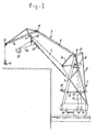
- the floating double link level luffing crane includes a base 2 turnable mounted on a pontoon 1 and a crane jib 3 which may be luffed in and luffed out and which substantially consists of a strut member 4, a backstay member 5 and a jib head member 6.
- the lower end of the strut member and the backstay member are hinged to the base 2 at 7, 8 respectively, whereas the jib head member is hinged to the strut member and the backstay member at 9, 10 respectively.
- the hoisting equipment includes a grab 13, winches 14 and cables 15 extending from the winches over some guide discs to the grab.
- a hydraulic luffing cylinder 16 For balancing use is made of a fixed counterweight 17 forming a part of the machine housing 18 and a movable counterweight 19. The latter is connected through levers 21 to the base 2 and through levers 22, 23 and 24 to the strut member 4.
- the crane drivers cab of usual constructions has a fixed position mostly right under hinge point 7.
- the cab 25 of the shown constructions is mounted at the end of a cab link 26 which on its turn is hinged to a carriage 27 movable along the strut member 4 of the crane.
- the carriage may be driven by non shown hydraulic motors which drive gears meshing into toothed racks along the strut member 4.
- the angular position of the cab link 26 with respect to the carriage 27 should be modified by means of hydraulic cylinders 28.
- the longitudinal direction of the cab link 26 remains substantially parallel to the longitudinal direction of the jib head member 6 of the crane. Compare figures 1 and 2.
- the cab in the entirely luffed in position of the crane and the lowest position of the carriage 27, may be just above or next to a platform 29 secured to the base or another part of the crane.
- the most important advantage of the disclosed crane is that the drivers cab 25 may always be moved in such a favourable position that the crane driver has the best position for the observation of the loading and unloading. By luffing the crane in and out, the cab will move along a substantially horizontal path which is good for the comfort of the driver.
- the cab link 16 has a hinge connection with at least one telescopic cab backstay member 23 and the carriage 27 may be moved by a winch equipment rather than by hydraulic motors.
- the carraige 27 may be guided with respect to the strut member 4 by sets of wheels 33 and side guide wheels 34. Some of the wheels 33 and 34 are mounted on a pivot lever 35 which is pushed by a Belleville spring 36 towards the strut member 4 so that a certain clearance is removed. To block the carriage in the working position and to may brake the carriage at the end of a movement, use is made of brake discs 37 co-operating with brake rails 38.
- This equipment includes two cables 39 extending each from a winch drum 41 along the strut member 4 over a disc 42 at the end of the strip member, over a disc 43 on the carriage 27 to a fixed connection point 44 on the strut member.
- Two discs 42 are rotatably mounted with respect to a rocker piece 45 swingably mounted on the strut member 4.
- cab link 26 As the cab link 26 is connected with the carriage 27 as well as with the upper end of the cab backstay members 32, these cab backstay members must be made shorter when the carriage 27 is displaced. Therefore use is made of two cables 51 extending from a winch drum 41 over guide rolls 52, 53 and over a guide roll 54 at the end of the cab backstay members to a fixed point 55 on the base.
- the winch drums 41 for the cables 51 and the winch drums 41 for the cables 39 are mounted next to each other on the same drive shaft; the first named drums are made smaller than the second named drums corresponding to the ratio of the length of the path covered by the carriage 27 and the adjusting path of the cab backstay members 32.
- the drums 41 are driven by hydraulic motors whereas on the outer circumference of the motors band brakes engages.
- the length of the cab backstay members 32 is fixed by hydraulic clamping members.
- the most important aim of the backstay members 32 is to stabilize the lever quadrangle: strut member 4, cab link 26, base 2 and cab backstay member 32; in each working position the cab will move along an approximately horizontal path when the crane is luffed in or luffed out without hydraulic driving means.
- hydraulic tension cylinders are mounted at the position of the fixed points 55.
- One of the alternatives is a construction which is rather similar to the construction of figures 3 - 6 and which differs therefrom by the fact that no separate winch equipment for the backstay members 32 of the cab are present. Instead one has taken care that the cab link in the entirely luffed in position of the crane engages a stop member of the cab with a big force (for instance about 30.000 N). As a consequence thereof the cab link can not pivot when the carriage 27 is moved along the strut member 4 by the cables 39, whereas the cab backstay members 32 will telescope in and telescope out.
Landscapes
- Engineering & Computer Science (AREA)
- Mechanical Engineering (AREA)
- Jib Cranes (AREA)
Priority Applications (1)
| Application Number | Priority Date | Filing Date | Title |
|---|---|---|---|
| AT83201213T ATE28320T1 (de) | 1982-08-26 | 1983-08-18 | Doppellenkerwippkran mit horizontalem lastweg. |
Applications Claiming Priority (2)
| Application Number | Priority Date | Filing Date | Title |
|---|---|---|---|
| NL8203338 | 1982-08-26 | ||
| NL8203338A NL8203338A (nl) | 1982-08-26 | 1982-08-26 | Hijskraan. |
Publications (3)
| Publication Number | Publication Date |
|---|---|
| EP0102123A2 true EP0102123A2 (fr) | 1984-03-07 |
| EP0102123A3 EP0102123A3 (en) | 1985-10-09 |
| EP0102123B1 EP0102123B1 (fr) | 1987-07-15 |
Family
ID=19840191
Family Applications (1)
| Application Number | Title | Priority Date | Filing Date |
|---|---|---|---|
| EP83201213A Expired EP0102123B1 (fr) | 1982-08-26 | 1983-08-18 | Grue du type à pantographe avec déplacement horizontal de la charge |
Country Status (5)
| Country | Link |
|---|---|
| US (1) | US4606469A (fr) |
| EP (1) | EP0102123B1 (fr) |
| AT (1) | ATE28320T1 (fr) |
| DE (1) | DE3372471D1 (fr) |
| NL (1) | NL8203338A (fr) |
Cited By (4)
| Publication number | Priority date | Publication date | Assignee | Title |
|---|---|---|---|---|
| WO1999020558A1 (fr) * | 1997-10-17 | 1999-04-29 | Compact Truck Ag | Vehicule porteur de grue pourvu d'une cabine supplementaire destinee au conducteur |
| NL1015068C2 (nl) * | 2000-05-01 | 2001-11-02 | H T J Internat B V | Hijskraan van het lemniscaattype. |
| DE202004019708U1 (de) * | 2004-12-21 | 2006-05-04 | Liebherr-Hydraulikbagger Gmbh | Umschlaggerät |
| DE102024117232A1 (de) * | 2024-06-19 | 2025-12-24 | Hamm Ag | Bedienstandsystem für eine Arbeitsmaschine |
Families Citing this family (10)
| Publication number | Priority date | Publication date | Assignee | Title |
|---|---|---|---|---|
| US4721213A (en) * | 1987-03-13 | 1988-01-26 | Eitel Jay M | Equipment and method for installing apparatus at elevated locations |
| US5727645A (en) * | 1996-05-03 | 1998-03-17 | Glazer Enterprises, Inc. | Aerial lift including a detachable end-hung basket |
| CN1057973C (zh) * | 1998-06-08 | 2000-11-01 | 上海港口机械制造厂 | 一种四连杆臂架自升式门座起重机 |
| JP2003146581A (ja) * | 2001-11-15 | 2003-05-21 | Mitsubishi Heavy Ind Ltd | クレーン及びクレーンの運転方法 |
| US6901877B1 (en) * | 2003-10-07 | 2005-06-07 | Michael Winnett | Foam block replacement barge |
| US8187045B2 (en) * | 2007-01-19 | 2012-05-29 | Thibodaux Ronald J | Air-propelled vessel with articulating member |
| DE202008005035U1 (de) * | 2008-04-11 | 2009-08-20 | Liebherr-Hydraulikbagger Gmbh | Arbeitsgerät und Notablasssystem |
| EP2189575B1 (fr) * | 2008-11-19 | 2021-06-30 | DEME Offshore BE N.V. | Offshore plate-forme auto-élévatrice et procédé |
| WO2013101899A1 (fr) * | 2011-12-30 | 2013-07-04 | National Oilwell Varco, L.P. | Grue à flèche double déport en eaux profondes |
| CN106829754B (zh) * | 2017-03-24 | 2018-05-22 | 徐州海伦哲专用车辆股份有限公司 | 一种绝缘高空作业车及其绝缘工作平台自动限幅方法 |
Family Cites Families (19)
| Publication number | Priority date | Publication date | Assignee | Title |
|---|---|---|---|---|
| DE610687C (de) * | 1935-03-14 | Demag Akt Ges | Wippkran, besonders Schwimmwippkran, fuer waagerechten Lastwippweg | |
| NL266662A (fr) * | ||||
| DE1073179B (de) * | 1960-01-14 | Kampnagel Aktiengesellschaft (vorm. Nagel S. Kaemp), Hamburg | Portalwippkran mit waagerechtem Lastweg | |
| DE471752C (de) * | 1929-02-16 | Bamag Meguin Akt Ges | Fuehrerhaus fuer verstellbare Ausleger von Drehkranen | |
| GB173330A (en) * | 1920-09-30 | 1921-12-30 | Frederick Gilbert Mitchell | Improvements in or relating to transporters, cranes and like hoisting and lowering apparatus |
| US2261483A (en) * | 1938-12-05 | 1941-11-04 | Manitowoc Shipbuilding Company | Load handling device |
| US2703180A (en) * | 1952-01-05 | 1955-03-01 | American Hoist & Derrick Co | Crane |
| SU119323A1 (ru) * | 1956-04-14 | 1958-11-30 | М.М. Идрисов | Строительный монтажный кран |
| DE1161669B (de) * | 1960-07-05 | 1964-01-23 | Krupp Ardelt Gmbh | Wippkran, insbesondere Doppellenkerwippkran |
| US3080981A (en) * | 1961-06-06 | 1963-03-12 | Schwermaschb Kirow Veb | Tower-crane cabin |
| DE1456493A1 (de) * | 1966-10-07 | 1970-01-29 | Hans Kaehlert | Verladeeinrichtung,insbesondere Container-Wippkran |
| DE2007837A1 (de) * | 1969-02-28 | 1970-10-15 | VEB Förderanlagen 7. Oktober, Magdeburg | Patentwesen, Ost-Berlin WP138234 Freizügig ortsveränderlicher Drehkran mit erhöhter Fahrerkanzel |
| DE1920528B2 (de) * | 1969-04-23 | 1977-12-29 | Fried. Krupp Gmbh, 4300 Essen | Niederlegbarer doppellenker-wippkran, insbesondere schwimmkran |
| DE2021121A1 (de) * | 1970-04-29 | 1971-11-11 | Kreschic Marijan Dipl Ing | Klimatisierbare Kabine mit Vollsicht |
| SE393585B (sv) * | 1975-09-12 | 1977-05-16 | Salen & Wicander Ab | For hantering av enhetslaster avsedd kran |
| US4220246A (en) * | 1978-06-15 | 1980-09-02 | Ray Louis F | Sheave adjustable balance crane |
| NL7810056A (nl) * | 1978-10-05 | 1980-04-09 | Stork Conrad Bv | Hijskraan. |
| US4257491A (en) * | 1979-01-29 | 1981-03-24 | Prescon Corporation | Scaffold apparatus |
| NL8003262A (nl) * | 1980-04-25 | 1981-11-16 | Boomse Metaalwerken | Kraan. |
-
1982
- 1982-08-26 NL NL8203338A patent/NL8203338A/nl unknown
-
1983
- 1983-08-18 DE DE8383201213T patent/DE3372471D1/de not_active Expired
- 1983-08-18 AT AT83201213T patent/ATE28320T1/de not_active IP Right Cessation
- 1983-08-18 EP EP83201213A patent/EP0102123B1/fr not_active Expired
-
1985
- 1985-09-23 US US06/778,298 patent/US4606469A/en not_active Expired - Fee Related
Cited By (5)
| Publication number | Priority date | Publication date | Assignee | Title |
|---|---|---|---|---|
| WO1999020558A1 (fr) * | 1997-10-17 | 1999-04-29 | Compact Truck Ag | Vehicule porteur de grue pourvu d'une cabine supplementaire destinee au conducteur |
| NL1015068C2 (nl) * | 2000-05-01 | 2001-11-02 | H T J Internat B V | Hijskraan van het lemniscaattype. |
| DE202004019708U1 (de) * | 2004-12-21 | 2006-05-04 | Liebherr-Hydraulikbagger Gmbh | Umschlaggerät |
| DE102024117232A1 (de) * | 2024-06-19 | 2025-12-24 | Hamm Ag | Bedienstandsystem für eine Arbeitsmaschine |
| EP4667656A1 (fr) * | 2024-06-19 | 2025-12-24 | Hamm AG | Système de poste de commande pour une machine de travail |
Also Published As
| Publication number | Publication date |
|---|---|
| EP0102123A3 (en) | 1985-10-09 |
| US4606469A (en) | 1986-08-19 |
| ATE28320T1 (de) | 1987-08-15 |
| EP0102123B1 (fr) | 1987-07-15 |
| DE3372471D1 (en) | 1987-08-20 |
| NL8203338A (nl) | 1984-03-16 |
Similar Documents
| Publication | Publication Date | Title |
|---|---|---|
| EP0102123B1 (fr) | Grue du type à pantographe avec déplacement horizontal de la charge | |
| KR0140085B1 (ko) | 가동균형추를 가진 인양능력향상비임부착장치와 이를 가진 크레인 | |
| US4021019A (en) | Heave compensating cranes | |
| US4729486A (en) | Lift enhancing beam attachment with movable counterweights | |
| US4976361A (en) | Mobile crane comprising a telescopic boom | |
| US2805781A (en) | Load stabilized crane | |
| US4360111A (en) | Crane with telescopic jib | |
| US4204664A (en) | Winch mechanism for crane | |
| US6499611B1 (en) | Mobile harbor crane for normal and heavy load operation | |
| GB714071A (en) | Improvements in or relating to apparatus for lifting, lowering or otherwise handlingloads | |
| US4492312A (en) | External pendant pay-out system with anti-droop control | |
| CA1223230A (fr) | Fleche portee par des suspensions fixes et mobile | |
| US5143233A (en) | Jib stretching and folding device for use in a crane | |
| CA1223843A (fr) | Systeme de type pendentif avec poulie flottante pour laisser filer ou rappeler le cable de suspension d'une fleche de levage | |
| US4453643A (en) | Cranes | |
| US4557391A (en) | Method of controlling the angle of a pivotal boom with extensible sections | |
| US4544071A (en) | External pendant pay-out system with anti-droop control | |
| US4892201A (en) | Jib system for cranes, especially mobile cranes | |
| US5131500A (en) | Vehicle hoist | |
| JP3974727B2 (ja) | 短艇揚収装置 | |
| GB2166411A (en) | Lifting device | |
| RU2097307C1 (ru) | Стреловой кран | |
| JP2003040578A (ja) | スライドレール型クレーン | |
| JPH0120398Y2 (fr) | ||
| SU1664726A1 (ru) | Грузоподъемный кран |
Legal Events
| Date | Code | Title | Description |
|---|---|---|---|
| PUAI | Public reference made under article 153(3) epc to a published international application that has entered the european phase |
Free format text: ORIGINAL CODE: 0009012 |
|
| AK | Designated contracting states |
Designated state(s): AT BE CH DE FR GB IT LI LU NL SE |
|
| PUAL | Search report despatched |
Free format text: ORIGINAL CODE: 0009013 |
|
| AK | Designated contracting states |
Designated state(s): AT BE CH DE FR GB IT LI LU NL SE |
|
| 17P | Request for examination filed |
Effective date: 19860212 |
|
| 17Q | First examination report despatched |
Effective date: 19861003 |
|
| GRAA | (expected) grant |
Free format text: ORIGINAL CODE: 0009210 |
|
| AK | Designated contracting states |
Kind code of ref document: B1 Designated state(s): AT BE CH DE FR GB IT LI LU NL SE |
|
| PG25 | Lapsed in a contracting state [announced via postgrant information from national office to epo] |
Ref country code: LI Effective date: 19870715 Ref country code: IT Free format text: LAPSE BECAUSE OF FAILURE TO SUBMIT A TRANSLATION OF THE DESCRIPTION OR TO PAY THE FEE WITHIN THE PRESCRIBED TIME-LIMIT;WARNING: LAPSES OF ITALIAN PATENTS WITH EFFECTIVE DATE BEFORE 2007 MAY HAVE OCCURRED AT ANY TIME BEFORE 2007. THE CORRECT EFFECTIVE DATE MAY BE DIFFERENT FROM THE ONE RECORDED. Effective date: 19870715 Ref country code: CH Effective date: 19870715 Ref country code: AT Effective date: 19870715 |
|
| REF | Corresponds to: |
Ref document number: 28320 Country of ref document: AT Date of ref document: 19870815 Kind code of ref document: T |
|
| PG25 | Lapsed in a contracting state [announced via postgrant information from national office to epo] |
Ref country code: SE Effective date: 19870731 |
|
| REF | Corresponds to: |
Ref document number: 3372471 Country of ref document: DE Date of ref document: 19870820 |
|
| ET | Fr: translation filed | ||
| PG25 | Lapsed in a contracting state [announced via postgrant information from national office to epo] |
Ref country code: LU Free format text: LAPSE BECAUSE OF NON-PAYMENT OF DUE FEES Effective date: 19870831 |
|
| REG | Reference to a national code |
Ref country code: CH Ref legal event code: PL |
|
| PLBE | No opposition filed within time limit |
Free format text: ORIGINAL CODE: 0009261 |
|
| STAA | Information on the status of an ep patent application or granted ep patent |
Free format text: STATUS: NO OPPOSITION FILED WITHIN TIME LIMIT |
|
| 26N | No opposition filed | ||
| PGFP | Annual fee paid to national office [announced via postgrant information from national office to epo] |
Ref country code: NL Payment date: 19890831 Year of fee payment: 7 |
|
| PGFP | Annual fee paid to national office [announced via postgrant information from national office to epo] |
Ref country code: FR Payment date: 19890926 Year of fee payment: 7 |
|
| PGFP | Annual fee paid to national office [announced via postgrant information from national office to epo] |
Ref country code: BE Payment date: 19890929 Year of fee payment: 7 |
|
| PGFP | Annual fee paid to national office [announced via postgrant information from national office to epo] |
Ref country code: GB Payment date: 19890930 Year of fee payment: 7 |
|
| PGFP | Annual fee paid to national office [announced via postgrant information from national office to epo] |
Ref country code: DE Payment date: 19891002 Year of fee payment: 7 |
|
| PGFP | Annual fee paid to national office [announced via postgrant information from national office to epo] |
Ref country code: LU Payment date: 19891005 Year of fee payment: 7 |
|
| PG25 | Lapsed in a contracting state [announced via postgrant information from national office to epo] |
Ref country code: FR Effective date: 19900427 |
|
| REG | Reference to a national code |
Ref country code: FR Ref legal event code: ST |
|
| PG25 | Lapsed in a contracting state [announced via postgrant information from national office to epo] |
Ref country code: GB Effective date: 19900818 |
|
| PG25 | Lapsed in a contracting state [announced via postgrant information from national office to epo] |
Ref country code: BE Effective date: 19900831 |
|
| BERE | Be: lapsed |
Owner name: FRANS SWARTTOUW B.V. Effective date: 19900831 |
|
| PG25 | Lapsed in a contracting state [announced via postgrant information from national office to epo] |
Ref country code: NL Effective date: 19910301 |
|
| NLV4 | Nl: lapsed or anulled due to non-payment of the annual fee | ||
| GBPC | Gb: european patent ceased through non-payment of renewal fee | ||
| PG25 | Lapsed in a contracting state [announced via postgrant information from national office to epo] |
Ref country code: DE Effective date: 19910501 |