EP0102144A1 - Maschine für Erdarbeiten - Google Patents
Maschine für Erdarbeiten Download PDFInfo
- Publication number
- EP0102144A1 EP0102144A1 EP83303180A EP83303180A EP0102144A1 EP 0102144 A1 EP0102144 A1 EP 0102144A1 EP 83303180 A EP83303180 A EP 83303180A EP 83303180 A EP83303180 A EP 83303180A EP 0102144 A1 EP0102144 A1 EP 0102144A1
- Authority
- EP
- European Patent Office
- Prior art keywords
- turntable
- gear
- carriage
- earth
- working machine
- Prior art date
- Legal status (The legal status is an assumption and is not a legal conclusion. Google has not performed a legal analysis and makes no representation as to the accuracy of the status listed.)
- Granted
Links
- 244000144980 herd Species 0.000 claims 1
- 238000005096 rolling process Methods 0.000 claims 1
- 238000010276 construction Methods 0.000 description 4
- 239000000463 material Substances 0.000 description 4
- 239000002828 fuel tank Substances 0.000 description 3
- 230000000694 effects Effects 0.000 description 2
- 239000010720 hydraulic oil Substances 0.000 description 2
- 230000002452 interceptive effect Effects 0.000 description 2
- 206010039203 Road traffic accident Diseases 0.000 description 1
- 208000027418 Wounds and injury Diseases 0.000 description 1
- 230000000903 blocking effect Effects 0.000 description 1
- 230000006378 damage Effects 0.000 description 1
- 230000001419 dependent effect Effects 0.000 description 1
- 230000000994 depressogenic effect Effects 0.000 description 1
- 208000014674 injury Diseases 0.000 description 1
- 239000003921 oil Substances 0.000 description 1
- 230000001360 synchronised effect Effects 0.000 description 1
Images






Classifications
-
- E—FIXED CONSTRUCTIONS
- E02—HYDRAULIC ENGINEERING; FOUNDATIONS; SOIL SHIFTING
- E02F—DREDGING; SOIL-SHIFTING
- E02F3/00—Dredgers; Soil-shifting machines
- E02F3/04—Dredgers; Soil-shifting machines mechanically-driven
- E02F3/28—Dredgers; Soil-shifting machines mechanically-driven with digging tools mounted on a dipper- or bucket-arm, i.e. there is either one arm or a pair of arms, e.g. dippers, buckets
- E02F3/30—Dredgers; Soil-shifting machines mechanically-driven with digging tools mounted on a dipper- or bucket-arm, i.e. there is either one arm or a pair of arms, e.g. dippers, buckets with a dipper-arm pivoted on a cantilever beam, i.e. boom
- E02F3/32—Dredgers; Soil-shifting machines mechanically-driven with digging tools mounted on a dipper- or bucket-arm, i.e. there is either one arm or a pair of arms, e.g. dippers, buckets with a dipper-arm pivoted on a cantilever beam, i.e. boom working downwardly and towards the machine, e.g. with backhoes
-
- E—FIXED CONSTRUCTIONS
- E02—HYDRAULIC ENGINEERING; FOUNDATIONS; SOIL SHIFTING
- E02F—DREDGING; SOIL-SHIFTING
- E02F3/00—Dredgers; Soil-shifting machines
- E02F3/04—Dredgers; Soil-shifting machines mechanically-driven
- E02F3/28—Dredgers; Soil-shifting machines mechanically-driven with digging tools mounted on a dipper- or bucket-arm, i.e. there is either one arm or a pair of arms, e.g. dippers, buckets
- E02F3/36—Component parts
- E02F3/38—Cantilever beams, i.e. booms;, e.g. manufacturing processes, forms, geometry or materials used for booms; Dipper-arms, e.g. manufacturing processes, forms, geometry or materials used for dipper-arms; Bucket-arms
- E02F3/382—Connections to the frame; Supports for booms or arms
- E02F3/384—Connections to the frame; Supports for booms or arms the boom being pivotable relative to the frame about a vertical axis
-
- E—FIXED CONSTRUCTIONS
- E02—HYDRAULIC ENGINEERING; FOUNDATIONS; SOIL SHIFTING
- E02F—DREDGING; SOIL-SHIFTING
- E02F9/00—Component parts of dredgers or soil-shifting machines, not restricted to one of the kinds covered by groups E02F3/00 - E02F7/00
- E02F9/08—Superstructures; Supports for superstructures
- E02F9/10—Supports for movable superstructures mounted on travelling or walking gears or on other superstructures
- E02F9/12—Slewing or traversing gears
- E02F9/121—Turntables, i.e. structure rotatable about 360°
-
- Y—GENERAL TAGGING OF NEW TECHNOLOGICAL DEVELOPMENTS; GENERAL TAGGING OF CROSS-SECTIONAL TECHNOLOGIES SPANNING OVER SEVERAL SECTIONS OF THE IPC; TECHNICAL SUBJECTS COVERED BY FORMER USPC CROSS-REFERENCE ART COLLECTIONS [XRACs] AND DIGESTS
- Y10—TECHNICAL SUBJECTS COVERED BY FORMER USPC
- Y10T—TECHNICAL SUBJECTS COVERED BY FORMER US CLASSIFICATION
- Y10T74/00—Machine element or mechanism
- Y10T74/18—Mechanical movements
- Y10T74/18056—Rotary to or from reciprocating or oscillating
- Y10T74/18272—Planetary gearing and slide
Definitions
- the present invention relates to an earth-working machine such as an excavator for digging ditches in road construction.
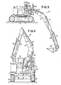
- a known excavator 1 for trenching in and along one lane of a road is placed on that lane, blocking off the traffic on the lane while allowing the traffic on the other lane.
- a bucket arm 2 of the excavator 1 is moved up and down to cause a bucket 3 on the bucket arm 2 to dig a trench 4 in and along the road lane.
- the material scooped by the bucket 3 is then dumped onto a loading platform 6 of a truck 5 positioned behind the excavator 1.
- the excavator 1 is required to move back in the direction of the arrow Z so as to avoid falling into the trench 4 which has just been dug.
- the present invention seeks to provide an earth-working machine having an earth-working mechanism capable of turning along a path of a reduced radius, and which therefore may operate without interfering with other activities around the machine, such as for example, traffic.
- the present invention seeks to provide an earth-working machine operable within a small space so as to avoid accidents such as traffic accidents or injuries to people around the machine.
- the present invention provides an earth-working machine comprising: a mobile chassis; a first gear mounted on the mobile chassis; a turntable rotatably mounted on the first gear; a carriage rotatably mounted on the turntable; a second gear mounted on the carriage and eccentric to the first gear; an earth-working mechanism mounted on the,-carriage; a first driving means mounted on the turntable in driving engagement with the first gear to rotate the turntable; and means engaging with the second gear for rotating the carriage about an axis of the second gear.
- the means for rotating the carriage comprises a shaft journalled in a bearing supported on the turntable and a first and a second pinion fixed to the shaft and meshing with the first and second gears, respectively.
- the first and second gears are internal gears.
- the carriage can be rotated in a direction opposite to the direction in which the turntable rotates in synchronism with rotation of the turntable when the first driving means is actuated.
- the first and second gears are external gears.
- the first driving means can be a hydraulic motor.
- the means for rotating the carriage has a second hydraulic motor, a first sprocket mounted on a first shaft of the second hydraulic motor, a second sprocket mounted on a second shaft journalled in a bearing supported on the turntable, a chain trained around the first sprockets, and a second pinion mounted on the second shaft and held in driving mesh with the second gear.
- the carriage can be rotated by the second gear.
- the carriage can be rotated by the second hydraulic motor independently of the turntable.
- the means comprises a second hydraulic motor mounted on the turntable and having a pinion held in driving mesh with the second gear.
- the carriage can be rotated by the second hydraulic motor independently of the turntable.
- the means can also include a shaft journalled in a bearing supported on the turntable and including a splined axial extension, a second pinion fixed to the shaft and meshing with the first gear, another pinion splined to the axial extension and normally held in driving mesh with the second gear, and clutch means actutable for shifting the other pinion on the axial extension axially out of meshing engagement with the second gear.
- the carriage can be rotated by the second hydraulic gear independently of the turntable when the clutch means is actuated.
- the clutch means has a support post mounted on the turntable, a lever pivotably mounted on the support post, a roller rotatably mounted on the lever and riding in a groove defined in the pinion the axial extension of the shaft, and an actuator rod connected to the lever for angularly moving the lever to shift that pinion out of meshing engagement with the second gear.
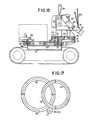
- the excavator is of the self-propelled type having a flat mobile chassis 10 supporting two pairs of wheels 11 which - .each carry an endless track 12.
- the mobile chassis 10 includes a central support base 13 ( Figures 3, 4 and 6) mounted thereon and having an upper annular flange on which an octagonal turntable 14 is rotatably mounted.
- the turntable 14 supports thereon an engine 15, a fuel tank 16, and a hydraulic oil tank 17 arranged along a rear edge of the turntable 14.
- a hydraulic motor 18 is also mounted on the turntable 14 adjacent to the fuel tank 16 and has a drive shaft 36 ( Figure 6) directed downwardly of the turntable 14.
- annular horizontal holder base 19 is fixedly mounted on the turntable 14 at a front edge thereof.
- the annular holder base 19 has an axis held in horizontally-eccentric relation to the axis of the support base 13 and hence the turntable 14.
- a circular carriage 20 is rotatably mounted coaxially on the holder base 19.
- the carriage 20 includes a vertical support 21 to which a pair of vertically spaced legs 22 is secured.
- a bracket 26 is pivotably mounted on the legs 22 and supports thereon a bent boom 27 which is vertically angularly movable about a pivot on the bracket 26.
- the boom 27 supports on its distal end a bucket arm 28 having a bucket 29 pivotally mounted on a distal end of the bucket arm 28.
- Hydraulic cylinders 30, 31, 32 are coupled respectively between the bracket 26 and a central portion of the boom 27, between a central portion of the boom 27 and an end of the bucket arm 28, and between the bucket arm 28 and the bucket 29.
- the boom 27, the bucket arm 28, the bucket 29, and the hydrulic cylinders 30, 31 32 jointly constitute an excavating mechanism 47.
- the bracket 26 also supports a seat base 23 on which there are mounted an operator seat 24 and a hydraulic control box 25 having a plurality of control levers 25a.
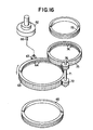
- an annular internal gear 33 is fixedly mounted on an annular flange of the support base 13.
- a slider ring 35 is disposed securely below the turntable 14 and rotatably fitted about the internal gear 33 with ball bearings 34 interposed therebetween. Accordingly, the turntable 14 is rotatable on the first gear 33.
- a pinion 37 is fixed to the drive shaft 36 of the hydraulic motor 18 and held in driving mesh with the internal gear 33.
- the turntable 14 has an L-shaped bracket 38 which extends downwards into the internal gear 33.
- a bearing 39 is fixed to the bracket 38 and a bearing 40 to the turntable 14.
- An intermediate vertical shaft 41 is rotatably journalled in the bearings 39, 40 and has a pinion 42 secured thereto and interposed between the bearings 39, 40.
- the pinion 42 meshes with the internal gear 33.
- the holder base 19 supports an annular holder 43.
- the carriage 20 has an annular internal gear 45 fixed to the underside thereof, which rotatably fits in the annular holder 43 with ball bearings 44.
- the carriage 20 is rotatable upon the annular holder 43.
- An upper end of the intermediate shaft 41 projects above the turntable 14 into the internal gear 45 and has a pinion 46 which meshes with the internal gear 45.
- the rotation of the pinion 46 causes the internal gear 45 in mesh therewith to rotate about its own axis within the annular holder 43 in a direction opposite to the direction in which the turntable 14 rotates. Accordingly, the carriage 20 secured to the internal gear 45 is also rotated in the direction opposite to that of the turntable 14.
- the excavating mechanism 47 is angularly moved with the carriage 20 from a front position to a rear position over the devices on the turntable 14 without the bucket 29 projecting sideways of the chassis 10. The excavating mechanism 47 is thus rotated about the axis of the carriage 20 while revolving about the axis of the turntable 14.
- the excavating mechanism 47 moves in a minimum space range on rearward movement over the chassis 10 without laterally projecting out of the width of the chassis 10.
- FIGs 9 through 14 illustrate an excavator according to another embodiment of the present invention.
- the excavator is similar in construction to the excavator shown in Figures 2 to 8, and hence only the structural difference will be described in detail.
- the turntable 14 supports another hydraulic motor 50 and a T-shaped support 51 dependent therefrom and supporting on its lower end a bearing mount 52 on which a pair of bearings 53, 54 is mounted within the support base 13.
- the hydraulic motor 50 has a drive shaft 55 extending downwards through the internal gear 33 into the support base 13 and has a lower end journalled in the bearing 53.
- An intermediate vertical shaft 56 is journalled in the bearing 40 on the turntable 14 and in the bearing 54 on the bearing mount 52.
- sprockets 57, 58 are secured to the shafts 55, 56, respectively, and an endless chain 59 is trained around the sprockets 57, 58.
- the pinion 46 held in mesh with the internal gear 45 is fixed to the upper end of the intermediate shaft 56, as shown in Figures 10 and 11.
- the bucket 29 ( Figure 2) with the material dug can be brought over the chassis 10 from the front to the rear position by actuating the hydraulic motors 18, 50 in synchronism to turn the turntable 14 and the carriage v 20 in opposite directions. More specifically, the hydraulic motor 18 is actuated to turn the turntable 14 about the axis of the internal gear 33. The carriage 20 is angularly moved with the turntable 14 about the axis thereof. The hydraulic motor 50 is also operated to rotate the pinion 46 through the drive shaft 55, the sprocket 57, the chain 59, the sprocket 58, and the intermediate shaft 56. The internal gear 45 is then caused by the pinion 46 to rotate about its own axis.
- the carriage 20 is rotated about the axis of the internal gear 45 while revolving around the axis of the turntable 14.
- the hydraulic motors 18, 50 are designed to rotate their shafts 36, 55 in opposite directions so that the excavating mechanism 47 ( Figures 13 and 14) will turn in a direction opposite to the direction in which the turntable 14'rotates, toward the rear position over the engine 15, the fuel tank 16 and the hydraulic oil tank 17.
- the carriage 20 will rotate through an angle twice larger than the angle of rotation of the turntable 14, the carriage 20 rotates through 360° when the turntable rotates through 180° to bring the excavating mechanism 47 from a front central position forward of the chassis 10 to a rear central position rearward of the chassis 10.
- the carriage 20 While the excavating mechanism 47 is rotating above the carriage 20, the carriage 20 is positioned on one side of the chassis 10 with the excavating mechanism 47 as folded being located on the other side. There is no danger for the excavating mechanism 47 to project laterally when the turntable makes angular movement through 90°. Therefore,-the excavating mechanism 47 can be turned around within the width of the chassis 10.
- the hydraulic motors 18, 50 can be actuated independently of each other to allow the excavating mechanism 47 to dig side trenches as shown in Figures 13 and 14. More specifically, the hydraulic motor 18 is actuated to turn the turntable 14 slightly until the carriage 20 is angularly shifted counterclockwise to one side of the chassis 14 through an angle of 8 1 as shown in Figure 13. Then the hydraulic motor 50 is operated to rotate the carriage 20 clockwise with respect to the turntable 14 through the same angle 8 1 .
- the excavating mechanism 47 is now directed parallel to the longitudinal direction of the excavator with the bucket located in a lateral position spaced a distance Wl from the longitudinal axis of the excavator so as to make the bucket ready for trenching a side ditch.
- the hydraulic cylinder of the excavating mechanism can be actuated to enable the bucket to dig a side ditch or laterally enlarge an existing ditch.
- the turntable 14 and the carriage 20 may be turned clockwise and counterclockwise through angle of 8 2 , respectively, to allow the bucket to trench another side ditch spaced a distance W2 from the longitudinal axis of the excavator.
- the turntable 14 and the carriage 20 may be adjusted in their angles of turn to enable the excavating mechanism 47 to project laterally beyond the width of the chassis 10 for digging an outside trench beyond one of the endless tracks.
- the support base 13 supports an annular external gear 63 in which a slider ring 65 is fitted.
- the slider ring 65 is secured to the turntable 14 and ball bearings 64 are interposed between the external gear 63 and the slider ring 65.
- a hydraulic motor 62 is fixedly mounted on the turntable 14 and has a drive shaft 66 extending downwards below the turntable 14 and has a pinion 67 held in driving mesh with the external gear 63.
- the turntable 14 has a shaft support ring 68 in which a bearing 70 with ball bearings 69 is fitted.
- An intermediate vertical shaft 71 is journalled in the bearing 70 and has on its lower end a pinion 72 held in mesh with the external gear 63.
- An annular holder 73 is mounted on the holder base 19 in coaxial relation therewith.
- the carriage 20 has an external gear 75 fixed to the underside thereof and rotatably fitted over the annular holder 73 in coaxial relation therewith and with ball bearings 74 interposed therebetween.
- the carriage 20 is thus rotatable about the axis of the annular holder 73.
- the intermediate shaft 71 has on its upper end a pinion 76 meshing with the external gear 75.
- the turntable 14 When the hydraulic motor 62 is actuated, the turntable 14 is rotated about the axis of the external gear 63. At the same time, the pinion 72 rotates in mesh with the external gear 63, and the pinion 76 also rotates to cause the external gear 75 and hence the carriage 20 to rotate about the axis of the annular holder 73 in a direction opposite to the direction in which the turntable 14 rotates. The carriage 20 is rotated about the axis of the annular holder 73 while revolving about the axis of the turntable 14. The bucket folded to the excavating mechanism is moved from a front to a rear position over the devices on the turntable 14 without interfering with objects located laterally outside of the width of the chassis 10.
- Figures 18 through 21 illustrate an excavator according to a still further embodiment of the present invention.
- the hydraulic motor 18, the internal gears 33 45, the pinion 42 and the bearings 39, 40 are basically of the same construction as that shown in Figure 6.
- the intermediate shaft 41 journalled in the bearing 39, 40 has a vertical axial extension 80 extending through the internal gear 45 and has axial splines 80a ( Figure 19).
- a pinion 81 is axially slidably splined to the axial extension 80 and normally held in driving mesh with the internal gear 45.
- the pinion 81 is axially movable out of meshing engagement with the internal gear 45 when shifted in the direction of the arrow ( Figure 19).
- a lever 82 is pivotably mounted at one end on a support post 83 mounted on the turntable 14 and has on the other end a roller 85 riding in a groove 84 defined in the pinion 81.
- An actuator lever 86 is connectd to the lever 82 and depressable toward the turntable 14 for angularly moving the lever 82 about the pivot on the support post 83 to shift the pinion 81 out of meshing engagement with the internal gear 45.
- the turntable 14 supports another hydraulic motor 87 below the carriage 20.
- the hydraulic motor 87 has a drive shaft 88 extending upwards into the internal gear 45 and has a pinion 89 held in driving mesh with the internal gear 45.
- the excavator of this embodiment operates for synchronous rotation of the turntable 14 and the carriage 20, the hydraulic motor 18 is actuated, the motor 87 is inactivated, and the pinion 81 kept in mesh with the internal gear 45.
- the turntable 14 is then rotated about the axis of the internal gear 33, and at the same time the pinions 42, 81 are rotated about their own axes.
- the internal gear 45 in mesh with the pinion 81 and hence the carriage ' 20 is rotated about the axis of the annular holder 43.
- the carriage 20 is thus rotated in one direction about its own axis while angularly moving with the turntable 14 in an opposite direction about the axis of the latter.
- the bucket folded to the excavating mechanism is moved over the turntable 14 from a front position to a rear position without laterally projecting out of the space range substantially equal to the width of the excavator chassis.
- the actuator lever 86 When it is desired to rotate the turntable 14 and the carriage 20 independently of each other, the actuator lever 86 is depressed to turn the lever 82 counterclockwise to shift the pinion 81 upwards out of meshing engagement with the internal gear 45.
- the internal gear 45 can then rotate independently of the internal gear 33.
- the hydraulic motor 87 is then actuated to rotate the pinion 89 and thereby the internal gear 45 in mesh therewith.
- the carriage 20 is therefore rotated solely by the hydraulic motor 87.
- the excavating mechanism can freely be-rotated with the carriage 20 through 360° to any desired position.
- the excavating mechanism can be positioned as desired with respect to the turntable 14; for example, the excavating mechanism may be shifted sideways to trench a side ditch, or may be stored over the turntable 14 with the latter remaining unrotated.
- the actuator lever 86 is moved back to bring the pinion 81 downwards to mesh with the internal gear 45.
- the hydraulic motor 18 is then actuated while the hydraulic motor 87 is rendered inoperative.
- the bucket of the excavating mechanism can be brought back and forth between front and rear positions with respect to the chassis over the devices mounted on the turntable.
- the bucket need not project laterally and hence interfere with activities around the excavator such as traffic on a lane of the road adjacent to the lane on which the excavator is used. Consequently, the digging operation of the excavator can be carried out in a minimum space range allowing as much traffic as possible adjacent to the excavator while in operation.
- the turntable and the carriage can be rotated synchronously in opposite directions through a simple gearing mechanism. With the other embodiments, the carriage can be rotated independently of the turntable so that the excavating mechanism can be laterally shifted for trenching desired side ditches or stored back above the turntable easily.
Landscapes
- Engineering & Computer Science (AREA)
- Mechanical Engineering (AREA)
- Mining & Mineral Resources (AREA)
- Civil Engineering (AREA)
- General Engineering & Computer Science (AREA)
- Structural Engineering (AREA)
- Earth Drilling (AREA)
- Component Parts Of Construction Machinery (AREA)
- Pit Excavations, Shoring, Fill Or Stabilisation Of Slopes (AREA)
- Vehicle Cleaning, Maintenance, Repair, Refitting, And Outriggers (AREA)
Priority Applications (1)
| Application Number | Priority Date | Filing Date | Title |
|---|---|---|---|
| DE8585115473T DE3380793D1 (en) | 1982-07-22 | 1983-06-02 | Earth-working machine |
Applications Claiming Priority (8)
| Application Number | Priority Date | Filing Date | Title |
|---|---|---|---|
| JP12846882A JPS5918823A (ja) | 1982-07-22 | 1982-07-22 | 掘削機 |
| JP128468/82 | 1982-07-22 | ||
| JP16297182A JPS5968435A (ja) | 1982-09-18 | 1982-09-18 | 掘削機の旋回機構 |
| JP162971/82 | 1982-09-18 | ||
| JP19212082A JPS5985037A (ja) | 1982-11-01 | 1982-11-01 | 掘削機の旋回機構 |
| JP192120/82 | 1982-11-01 | ||
| JP1337683A JPS59138625A (ja) | 1983-01-28 | 1983-01-28 | 掘削機の連動機構 |
| JP13376/82 | 1983-01-28 |
Related Child Applications (1)
| Application Number | Title | Priority Date | Filing Date |
|---|---|---|---|
| EP85115473.2 Division-Into | 1985-12-05 |
Publications (2)
| Publication Number | Publication Date |
|---|---|
| EP0102144A1 true EP0102144A1 (de) | 1984-03-07 |
| EP0102144B1 EP0102144B1 (de) | 1987-12-23 |
Family
ID=27455976
Family Applications (1)
| Application Number | Title | Priority Date | Filing Date |
|---|---|---|---|
| EP83303180A Expired EP0102144B1 (de) | 1982-07-22 | 1983-06-02 | Maschine für Erdarbeiten |
Country Status (5)
| Country | Link |
|---|---|
| US (2) | US4596508A (de) |
| EP (1) | EP0102144B1 (de) |
| AU (1) | AU538318B2 (de) |
| CA (1) | CA1195661A (de) |
| DE (1) | DE3375034D1 (de) |
Cited By (3)
| Publication number | Priority date | Publication date | Assignee | Title |
|---|---|---|---|---|
| EP0116474A1 (de) * | 1983-02-12 | 1984-08-22 | Kabushiki Kaisha Hikoma Seisakusho | Maschine für Erdarbeiten |
| DE3425838A1 (de) * | 1983-07-14 | 1985-01-31 | Karl Schaeff GmbH & Co, Maschinenfabrik, 7183 Langenburg | Loeffelbagger |
| FR2734294A1 (fr) * | 1995-05-15 | 1996-11-22 | Sdto | Engin motorise pour creuser des tranchees ou analogues dans le sol |
Families Citing this family (23)
| Publication number | Priority date | Publication date | Assignee | Title |
|---|---|---|---|---|
| CA1195661A (en) * | 1982-07-22 | 1985-10-22 | Yokichi Nagasawa | Earth-working machine |
| DE3565295D1 (en) * | 1984-03-06 | 1988-11-03 | Hikoma Seisakusho Kk | Earth-working machine |
| JPS62142834A (ja) * | 1985-12-17 | 1987-06-26 | Komatsu Ltd | クレ−ンのエンジン制御装置 |
| DE3843753A1 (de) * | 1988-12-24 | 1990-06-28 | Schaeff Karl Gmbh & Co | Baggerarm |
| JPH0745745B2 (ja) * | 1989-03-23 | 1995-05-17 | 油谷重工株式会社 | 旋回減速機 |
| US5163570A (en) * | 1991-05-28 | 1992-11-17 | Paccar Inc. | Load sensing device for a boom mounted on a vehicle |
| AT963U1 (de) * | 1995-01-25 | 1996-08-26 | Humer Friedhofstech Gmbh | Selbstfahrender kleinbagger |
| KR100236117B1 (ko) * | 1996-01-30 | 1999-12-15 | 세구치 류이치 | 스윙식 유압쇼벨 |
| DE29610630U1 (de) | 1996-06-17 | 1997-11-13 | BISON stematec Maschinenbau- und Hubarbeitsbühnen Produktionsgesellschaft mbH, 02708 Löbau | Fahrbare Hubarbeitsbühne |
| DE19754775A1 (de) * | 1997-11-28 | 1999-06-10 | Mannesmann Ag | Schienengebundener Mobilkran |
| US6729831B1 (en) * | 1998-08-31 | 2004-05-04 | Yanmar Co., Ltd. | Extremely-small-swing working machine |
| US6322104B1 (en) | 1999-03-02 | 2001-11-27 | Clark Equipment Company | Excavator frame and method of assembly |
| US6170350B1 (en) | 1999-06-08 | 2001-01-09 | Perfection Gear, Inc. | Gear reducer drive assembly |
| US7383906B2 (en) * | 2002-08-29 | 2008-06-10 | Jlg Industries, Inc. | Rotatable and telescopic work machine |
| DE20305683U1 (de) * | 2003-04-08 | 2004-08-19 | Liebherr-Werk Ehingen Gmbh | Fahrbarer Kran |
| US7303238B1 (en) * | 2004-05-19 | 2007-12-04 | Oldenburg Group Incorporated | Mine scaling vehicle |
| GB2417478A (en) * | 2004-08-27 | 2006-03-01 | Cole Technology Ltd | A boom assembly for an excavation vehicle |
| WO2006135863A1 (en) * | 2005-06-10 | 2006-12-21 | The Charles Machine Works, Inc. | Turret mounted compact tool carrier |
| US8596165B2 (en) * | 2006-06-09 | 2013-12-03 | Parker-Hannifin Corporation | Multiple gear motor drive |
| JP5581903B2 (ja) * | 2010-08-31 | 2014-09-03 | トヨタ紡織株式会社 | 転積装置 |
| CN102409714B (zh) * | 2011-08-05 | 2014-04-02 | 徐州工程学院 | 一种挖掘机阻尼式旋转工作台 |
| US10508409B2 (en) | 2018-04-18 | 2019-12-17 | Caterpillar Inc. | Machine with a boom assembly and connection member |
| NL2024981B1 (en) * | 2020-02-24 | 2021-10-14 | Hudson I P B V | Electric drive of mobile apparatus |
Citations (3)
| Publication number | Priority date | Publication date | Assignee | Title |
|---|---|---|---|---|
| US1528222A (en) * | 1922-11-13 | 1925-03-03 | Miller Byron Wooten | Combination power shovel and ditcher |
| US4183711A (en) * | 1975-12-24 | 1980-01-15 | Hans Schaeff | Mobile power shovel |
| GB2092102A (en) * | 1981-01-31 | 1982-08-11 | Kishi Mitsuhiro | Bucket excavator |
Family Cites Families (6)
| Publication number | Priority date | Publication date | Assignee | Title |
|---|---|---|---|---|
| US287631A (en) * | 1883-10-30 | Dredging machine | ||
| FR1556243A (de) * | 1967-11-13 | 1969-02-07 | ||
| FR1594043A (de) * | 1968-12-04 | 1970-06-01 | ||
| JPS5589546A (en) * | 1978-12-25 | 1980-07-07 | Kubota Ltd | Driving structure for work machine |
| US4392776A (en) * | 1981-05-15 | 1983-07-12 | Westinghouse Electric Corp. | Robotic manipulator structure |
| CA1195661A (en) * | 1982-07-22 | 1985-10-22 | Yokichi Nagasawa | Earth-working machine |
-
1983
- 1983-04-27 CA CA000426814A patent/CA1195661A/en not_active Expired
- 1983-06-02 EP EP83303180A patent/EP0102144B1/de not_active Expired
- 1983-06-02 DE DE8383303180T patent/DE3375034D1/de not_active Expired
- 1983-06-13 US US06/503,688 patent/US4596508A/en not_active Expired - Fee Related
- 1983-07-12 AU AU16757/83A patent/AU538318B2/en not_active Ceased
-
1987
- 1987-10-08 US US07/107,868 patent/US4797060A/en not_active Expired - Fee Related
Patent Citations (3)
| Publication number | Priority date | Publication date | Assignee | Title |
|---|---|---|---|---|
| US1528222A (en) * | 1922-11-13 | 1925-03-03 | Miller Byron Wooten | Combination power shovel and ditcher |
| US4183711A (en) * | 1975-12-24 | 1980-01-15 | Hans Schaeff | Mobile power shovel |
| GB2092102A (en) * | 1981-01-31 | 1982-08-11 | Kishi Mitsuhiro | Bucket excavator |
Cited By (3)
| Publication number | Priority date | Publication date | Assignee | Title |
|---|---|---|---|---|
| EP0116474A1 (de) * | 1983-02-12 | 1984-08-22 | Kabushiki Kaisha Hikoma Seisakusho | Maschine für Erdarbeiten |
| DE3425838A1 (de) * | 1983-07-14 | 1985-01-31 | Karl Schaeff GmbH & Co, Maschinenfabrik, 7183 Langenburg | Loeffelbagger |
| FR2734294A1 (fr) * | 1995-05-15 | 1996-11-22 | Sdto | Engin motorise pour creuser des tranchees ou analogues dans le sol |
Also Published As
| Publication number | Publication date |
|---|---|
| AU1675783A (en) | 1984-04-05 |
| EP0102144B1 (de) | 1987-12-23 |
| US4596508A (en) | 1986-06-24 |
| US4797060A (en) | 1989-01-10 |
| AU538318B2 (en) | 1984-08-09 |
| DE3375034D1 (en) | 1988-02-04 |
| CA1195661A (en) | 1985-10-22 |
Similar Documents
| Publication | Publication Date | Title |
|---|---|---|
| EP0102144A1 (de) | Maschine für Erdarbeiten | |
| US3512589A (en) | Earth moving apparatus | |
| CA3042386A1 (en) | System and method for defining a zone of operation for a lift arm | |
| GB2086347A (en) | Articulated arm for excavator machines | |
| EP0187944B1 (de) | Maschine für Erdarbeiten | |
| CA1260965A (en) | Bench mining method and apparatus | |
| US3160284A (en) | Weight stabilizing load handling machine | |
| US2747307A (en) | Adjustable mechanism for endless conveyor type ditching machine | |
| JP4049825B2 (ja) | シルト除去掘削ホイールのエゼクター機構 | |
| US4116014A (en) | Excavating and pipeline installation system | |
| GB2092102A (en) | Bucket excavator | |
| KR950008727B1 (ko) | 전선회형(全旋回型)백호우(backhoe)작업차 | |
| EP0156546B1 (de) | Maschine zur Bodenbearbeitung | |
| WO2001027397A1 (en) | Earth moving apparatus | |
| JPS5918823A (ja) | 掘削機 | |
| US1246524A (en) | Multiple-wheel trench-machine. | |
| KR870000792B1 (ko) | 굴착기(掘削機) | |
| US2878951A (en) | Side digger | |
| JP3646441B2 (ja) | 運搬車 | |
| US4329087A (en) | Excavating and pipeline installation system | |
| JPS5826454B2 (ja) | 掘削機 | |
| US1491850A (en) | Excavating machine | |
| JPS6138294B2 (de) | ||
| US2013170A (en) | Backfiller mechanism | |
| JPH0343414B2 (de) |
Legal Events
| Date | Code | Title | Description |
|---|---|---|---|
| PUAI | Public reference made under article 153(3) epc to a published international application that has entered the european phase |
Free format text: ORIGINAL CODE: 0009012 |
|
| 17P | Request for examination filed |
Effective date: 19830708 |
|
| AK | Designated contracting states |
Designated state(s): CH DE FR GB IT LI SE |
|
| 17Q | First examination report despatched |
Effective date: 19860421 |
|
| GRAA | (expected) grant |
Free format text: ORIGINAL CODE: 0009210 |
|
| AK | Designated contracting states |
Kind code of ref document: B1 Designated state(s): CH DE FR GB IT LI SE |
|
| ITF | It: translation for a ep patent filed | ||
| ET | Fr: translation filed | ||
| REF | Corresponds to: |
Ref document number: 3375034 Country of ref document: DE Date of ref document: 19880204 |
|
| PLBE | No opposition filed within time limit |
Free format text: ORIGINAL CODE: 0009261 |
|
| STAA | Information on the status of an ep patent application or granted ep patent |
Free format text: STATUS: NO OPPOSITION FILED WITHIN TIME LIMIT |
|
| 26N | No opposition filed | ||
| ITTA | It: last paid annual fee | ||
| EAL | Se: european patent in force in sweden |
Ref document number: 83303180.0 |
|
| PGFP | Annual fee paid to national office [announced via postgrant information from national office to epo] |
Ref country code: DE Payment date: 19960507 Year of fee payment: 14 |
|
| PGFP | Annual fee paid to national office [announced via postgrant information from national office to epo] |
Ref country code: FR Payment date: 19960523 Year of fee payment: 14 Ref country code: CH Payment date: 19960523 Year of fee payment: 14 |
|
| PGFP | Annual fee paid to national office [announced via postgrant information from national office to epo] |
Ref country code: GB Payment date: 19960528 Year of fee payment: 14 |
|
| PGFP | Annual fee paid to national office [announced via postgrant information from national office to epo] |
Ref country code: SE Payment date: 19960627 Year of fee payment: 14 |
|
| REG | Reference to a national code |
Ref country code: GB Ref legal event code: 732E |
|
| REG | Reference to a national code |
Ref country code: CH Ref legal event code: PUE Owner name: JAPANIC CORPORATION TRANSFER- NIKKEN CORPORATION Ref country code: CH Ref legal event code: PFA Free format text: KABUSHIKI KAISHA HIKOMA SEISAKUSHO TRANSFER- JAPANIC CORPORATION |
|
| REG | Reference to a national code |
Ref country code: FR Ref legal event code: TP Ref country code: FR Ref legal event code: CD Ref country code: FR Ref legal event code: CA |
|
| PG25 | Lapsed in a contracting state [announced via postgrant information from national office to epo] |
Ref country code: GB Effective date: 19970602 |
|
| PG25 | Lapsed in a contracting state [announced via postgrant information from national office to epo] |
Ref country code: SE Effective date: 19970603 |
|
| PG25 | Lapsed in a contracting state [announced via postgrant information from national office to epo] |
Ref country code: LI Free format text: LAPSE BECAUSE OF NON-PAYMENT OF DUE FEES Effective date: 19970630 Ref country code: CH Free format text: LAPSE BECAUSE OF NON-PAYMENT OF DUE FEES Effective date: 19970630 |
|
| GBPC | Gb: european patent ceased through non-payment of renewal fee |
Effective date: 19970602 |
|
| REG | Reference to a national code |
Ref country code: CH Ref legal event code: PL |
|
| PG25 | Lapsed in a contracting state [announced via postgrant information from national office to epo] |
Ref country code: FR Free format text: LAPSE BECAUSE OF NON-PAYMENT OF DUE FEES Effective date: 19980227 |
|
| EUG | Se: european patent has lapsed |
Ref document number: 83303180.0 |
|
| PG25 | Lapsed in a contracting state [announced via postgrant information from national office to epo] |
Ref country code: DE Free format text: LAPSE BECAUSE OF NON-PAYMENT OF DUE FEES Effective date: 19980303 |
|
| REG | Reference to a national code |
Ref country code: FR Ref legal event code: ST |
|
| REG | Reference to a national code |
Ref country code: FR Ref legal event code: ST |