EP0102248B1 - Dispositif pour commander la vitesse et la position d'un moteur électrique - Google Patents
Dispositif pour commander la vitesse et la position d'un moteur électrique Download PDFInfo
- Publication number
- EP0102248B1 EP0102248B1 EP83305020A EP83305020A EP0102248B1 EP 0102248 B1 EP0102248 B1 EP 0102248B1 EP 83305020 A EP83305020 A EP 83305020A EP 83305020 A EP83305020 A EP 83305020A EP 0102248 B1 EP0102248 B1 EP 0102248B1
- Authority
- EP
- European Patent Office
- Prior art keywords
- motor
- microprocessor
- time
- signal
- arrangement according
- Prior art date
- Legal status (The legal status is an assumption and is not a legal conclusion. Google has not performed a legal analysis and makes no representation as to the accuracy of the status listed.)
- Expired
Links
Images




Classifications
-
- G—PHYSICS
- G05—CONTROLLING; REGULATING
- G05B—CONTROL OR REGULATING SYSTEMS IN GENERAL; FUNCTIONAL ELEMENTS OF SUCH SYSTEMS; MONITORING OR TESTING ARRANGEMENTS FOR SUCH SYSTEMS OR ELEMENTS
- G05B19/00—Program-control systems
- G05B19/02—Program-control systems electric
- G05B19/18—Numerical control [NC], i.e. automatically operating machines, in particular machine tools, e.g. in a manufacturing environment, so as to execute positioning, movement or co-ordinated operations by means of program data in numerical form
- G05B19/416—Numerical control [NC], i.e. automatically operating machines, in particular machine tools, e.g. in a manufacturing environment, so as to execute positioning, movement or co-ordinated operations by means of program data in numerical form characterised by control of velocity, acceleration or deceleration
-
- H—ELECTRICITY
- H02—GENERATION; CONVERSION OR DISTRIBUTION OF ELECTRIC POWER
- H02P—CONTROL OR REGULATION OF ELECTRIC MOTORS, ELECTRIC GENERATORS OR DYNAMO-ELECTRIC CONVERTERS; CONTROLLING TRANSFORMERS, REACTORS OR CHOKE COILS
- H02P23/00—Arrangements or methods for the control of AC motors characterised by a control method other than vector control
- H02P23/0077—Characterised by the use of a particular software algorithm
Definitions
- the present invention relates to an arrangement for controlling the speed and positioning of a direct-current motor, used for example to position members of an office machine.
- a typical application of the arrangement according to the invention is to the motor controlling the carriage, the printing head or the platen of an electronic typewriter.
- An arrangement for controlling a direct-current motor wherein a microprocessor is used for generating logical signals which drive a control circuit for the motor.
- the logical signals are such as to accelerate the motor in either sense, in order to maintain the speed of rotation thereof always close to a predetermined theoretical speed stored in a read-only memory of the microprocessors.
- acceleration in the sense will speed up the motor while acceleration in the other sense will actually decelerate the motor, referred to herein also as braking the motor.
- the actual speed of the motor is detected by means of a transducer connected to the shaft of the motor and is compared with the theoretical speed.
- a signal indicating the difference between the two speeds is sent to a second read-only memory of the microprocessor in which are stored the acceleration and deceleration values which the motor must employ to bring itself towards the theoretical speed.
- This control arrangement is rather complicated, because with every value of the difference between the theoretical speed and the actual speed there is associated a different acceleration or deceleration value.
- the motor is not only subjected to continuous variations of state which are necessary for driving it, but is also subjected to forcing accelerations of variable degree.
- the object of the present invention is to provide an arrangement for controlling a direct-current motor which is simple and at the same time very reliable and which operates in such manner that the motor is not continuously subjected to variations of acceleration or deceleration values.
- the arrangement according to the invention comprises means for generating electric signals indicating the angular position of the motor and the actual time of covering a predetermined angular step, an electric control circuit adapted selectively to short-circuit and accelerate the motor in either sense, and a microprocessor connected to the control circuit and to the angular-position signal generator, characterised in that the microprocessor stores the theoretical times for covering each angular step as a function of the full amplitude of the rotation that the motor must effect and the microprocessor is arranged to compare the actual times with the theoretical times for covering each step to determine in what stage the control circuit must keep the motor and the duration of each state.
- an arrangement 20 according to the invention is mounted on a typewriter 21 which comprises a keyboard 22, a command console 23, a platen 24, a carriage 25 slidable on guides 26 parallel to the platen 24, and a type daisy wheel 28, for example as described in the Applicant's Italian Patent No. 1.016.590.
- a first direct-current electric motor 29 is mounted coaxial with the platen 24 and effects the rotation thereof.
- a second direct-current electric motor 30 effects the shifting of the carriage 25 in front of the platen 24 through the medium of a wire cable 31, to define in this way the various printing positions along a printing line.
- a third electric motor 32 which is also of direct-current type, is mounted on the carriage 25 and effects the rotation of the type wheel 28 to position the selected character in the striking position.
- a printing hammer 33 which is also mounted on the carriage 25, is controlled by an electromagnet 34 to bring the selected character against the platen 24.
- optical transducers 35, 36 and 37 are connected to the shafts of the motors 29, 30 and 32, respectively, to generate in known manner timing signals.
- the optical transducers 35, 36 and 37 may be, for example, of the type described in British Patent Publication GB 2 062 220 and are therefore not described in detail.
- the arrangement 20 according to the invention is adapted to control the three motors 29, 30 and 32, but for brevity and simplicity it will now be described in detail with reference to a single one of the motors and its transducer.
- the arrangement 20 (Fig. 3) comprises a microprocessor 40 of known type, for example of Intel 8641, whose functions, which will be better specified hereinafter, are to control the elements connected to it and in particular a control circuit 41 which, through a power circuit or driver 42, directly controls the motor 29 (30, 32).
- the transducers 35 (36, 37) associated with the motor to be controlled is connected to the microprocessor 40 and to the control circuit 41.
- the useful signals which are taken from the transducer 35 (36, 37) are the analog signal FTA and the logical signals STB and STF.
- the logical signal STA is formed by the control circuit 41. It is obvious that this choice is not essential for the purposes of control of the motor according to the present invention and that other methods of generating logical and analog signals relating to the rotation of the motor may be used.
- the analog signal FTA be correlated directly with the angle by which the rotor of the motor which it is desired to control rotates.
- the period pe of the signal FTA corresponds to an angle of rotation of the rotor given by 360° divided by the number of obturating elements which are angularly spaced around the disc of the transducer. This angle is called the incremental angle, or simply the increment.
- the analog signal FTA is of sinusoidal type and, in the zones of monotony, that is where it is always increasing or always decreasing with increase in the angle of rotation, it can be regarded as a true and proper error signal with respect to any considered reference position.
- the greater the position error AX the greater is the value of the signal FTA.
- the analog signal FTA is handled by the control circuit 41 (Fig. 3), while the logical signals STA, STB and STF are processed by the microprocessor 40.
- the latter is programmed in such manner as to give as output three logical signals M1, M2 and M3, which are directed to the control circuit 41 to produce well-defined states of the motor, as will be better described further on, in accordance with a certain program stored in the microprocessor, as a function of the value of the angle by which the motor must rotate, that is as a function of the number N of increments which separate the current position of the rotor of the motor from the position to be reached, called the target.
- the microprocessor 40 controls the rotation of the motor digitally until it is brought into the vicinity of the target, after which precise positioning takes place by exploiting the analog signal FTA in its zone of monotony.
- the elementary step pa that the microprocessor utilizes as a reference parameter for its counts is not always constant and does not always correspond to a predetermined rotation of the rotor of the motor.
- An adjustment segment is one of the sections into which the distance between the current position and the target to be reached is divided. The number of segments will be indicated by the reference M. Determination of the value of the step pa for each segment involves a compromise between two contradictory requirements:
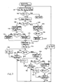
- microprocessor 40 which can be represented diagrammatically, in broad outline, in accordance with the flowchart of Figure 5.
- a first phase 50 there is acquisition of the sense of rotation and of the number N of increments to be gone through starting from the current position of the rotor.
- This information is acquired by the microprocessor through an input channel 49 (Fig. 3), from the keyboard 22 of the machine 21 (Fig. 1), or by means of conversation with another processing unit of the machine, known per se and not shown in the drawings.
- a second phase 51 there is determination, on the basis of a predetermined running table stored in the microprocessor, of the adjustment segments to be employed to go from the current position to the target.
- An example of a running table is illustrated diagrammatically in Fig. 6, where the ordinate T R indicates the value of the reference time, or ideal time, that the motor needs to rotate by one step pa and so maintain a predetermined speed.
- the microprocessor 40 truncates the function, established at the design stage, at a suitable abscissa, namely the abscissa N, where N is the datum acquired in the stage 50.
- N, to N 4 and T, to T 4 are determined at the design stage and stored in a look-up table.
- the microprocessor 40 is thus able to establish, for each value of N entered, the various adjustment segments M and, for each of them, both the reference time T R and the length of the step pa. For each adjustment segment, the microprocessor 40 must therefore be able to effect recognition of the step selected. This is achieved, for example, by means of suitable specific routines which, since they are not essential for the purpose of understanding the present invention, are not described for the sake of brevity.
- the microprocessor 40 In addition to the reference time T R , the microprocessor 40 also takes into consideration a threshold time T s , below which the time to cover a step pa must not fall, that is, it is required that the speed of rotation needed to cover a step pa should not be greater than a predetermined limit speed, having regard to the characteristics of the motor.
- the microprocessor 40 is therefore able to associate, with each N entered, the sequence of parameters to be effected and, for each segment: the number of steps, which we will call PAS, which constitute the adjustment segment; the length of the step pa established in this segment; the value T R and a proportionality constant h R therefore; the value T s and a proportionality constant h s thereof.
- phase 52 starting of the motor takes place.
- the microprocessor 40 in the inoperative condition, with the motor at a standstill in a position of equilibrium, corresponding to the edge of one of the signals STA or STB, for example in the position A (Fig. 2), the microprocessor 40 is in a "position loop" state.
- the microprocessor 40 accelerates the motor in the determined running direction, for example that of the arrow 54 in Figure 2, as far as a leading edge B, of the signal STB corresponding to a peak of the analog signal FTA.
- the microprocessor 40 which, as will be seen hereinafter, also calculates from time to time the effective or actual time Tp of covering the step in progress, determines in this stage the value of a fictitious time Tp o for covering the first step (from the position A to the edge B 1 of the signal STB).
- the phase 53 (Fig. 5) is that during which the microprocessor 40, generating logical signals M1, M2 and M3, effects the digital driving proper of the motor 29 until it brings it into the vicinity of the target.
- This logical phase is represented in detail in the diagram of Figure 7. More particularly, the phase 53 comprises a first subphase 101 in which there is possible updating of the variables T R , h R , T s and h s in accordance with the chart of Figure 6, of the value of PAS, which as has been seen is the number of steps to be effected in the segment considered, and of the value of the effective time Tp, which value is given by the sum of the times necessary to perform a series of elementary operations which cause the motor to cover one step pa.
- the microprocessor 40 checks whether the number PAS of steps still to be completed, is equal to zero: in the affirmative case, this is the end of this adjustment phase and return to the main flow of Fig. 5 occurs, while in the negative case the value PAS is decremented by one unit in a subphase 103 and the microprocessor goes on to check in a subphase 104 whether the threshold time T s is greater than the actual time Tp of covering of the preceding step, or than the fictitious time Tp o , in the case of effecting the first step after starting off.
- the microprocessor 40 operates on the signals M1, M2 and M3 in a subphase 105 to put the motor immediately into a short-circuit condition, while there is carried out the calculation of the value of a forcing time T F which is equal to the product of the proportionality constant h s and the absolute difference between the values T S and Tp.
- a variable T is moreover defined which is set equal to the time T s .
- subphase 106 which is such as to cause the operations of the branch 108 to the right of the subphase 104 to last the same time as the operations of the branch 109 to the left of the subphase 104, there is a subphase 107 in which it is established that the forcing of the motor will have to be a braking, or a reverse command.
- the microprocessor 40 in a subphase 110, puts the motor 29 into the acceleration condition, while there is carried out the calculation of the time of the following forcing, T F which is equal to the product of the proportionality constant h R and the absolute difference between the values of T R and Tp.
- T F which is equal to the product of the proportionality constant h R and the absolute difference between the values of T R and Tp.
- the variable T is set equal to the reference time T R .
- a subphase 111 there is a check whether T R is greater than Tp. In the affirmative case, a subphase 113 establishes that the following forcing will have to be a braking, while in the opposite case a subphase 112 establishes that this forcing will be an acceleration.
- the time taken by the microprocessor 40 to execute the operations from the subphase 101 included to the subphase 114 excluded is indicated by Q.
- the microprocessor 40 executes a series of operations which, in addition to giving further commands to the motor 29 (30, 32), also serve for counting the time Tp of actual covering of the step in progress or current step. Up to the phase 114, the time Tp taken into consideration has been that taken to cover the preceding step but now the duration of the current step must be determined for utilization in the execution of the next step.
- a subphase 115 the value Tp is put equal to zero and in a following subphase 116 the new time Tp is compared with the forcing time T F . So long as the new time Tp remains less than or equal to the time T F , the microprocessor 40 goes on to a subphase 117 to check whether the step has been covered, that is whether a predetermined leading edge of a logical signal STA or STB has been generated, as will also be seen in the course of the description of an example of operation. In the affirmative case, there is a return upstream of the subphase 101, via a subphase 118, which increments the time Tp taken to cover the current step by the abovementioned calculation time Q.
- the acceleration or braking ceases and there occurs a subphase 120 in which the motor 29 is short-circuited and a following subphase 121 in which the time Tp is compared with the variable T, which as has been seen may be equal to T R or T S . If T is less than or equal to T, the microprocessor 40 goes on to a subphase 122 to check whether the step pa has been covered. In the affirmative case, there is a return upstream of the subphase 101, via the subphase 118, while in the negative case a subphase 123 occurs in which the time Tp which is being calculated is incremented by another unit.
- the microprocessor 40 provides for updating of the variables, including the value of Tp. If, for example, operation passes from a segment in which the step pa is equal to one increment to a segment in which the step is equal to half an increment, in addition to the updating of the variables T R , h R , T S , h s and PAS, the time Tp counted in the old segment is halved in value, before it is used in decision 104 in the new segment.
- the phase 55 comprises the phase 55 comprises the subphase 201 (Fig. 8) in which the microprocessor 40 firstly brakes the motor 29 by operating on the signals M1, M2 and M3, for a time in which a and ⁇ are constants depending on the characteristics of the motor which is being controlled and T RP is the time in which it is desired that the motor shall cover the last step.
- a subphase 202 in which analog control is introduced on the signal FTA.
- the microprocessor 40 goes on to a subphase 203 to check whether, through the generation of a predetermined edge of the signal STB, the signal FTA remains in the zone of monotony concerned.
- the microprocessor 40 passes to a subphase 204 in which it checks whether the predetermined time T has elapsed and, if this is confirmed, passes to a further subphase 205, in which there is a reduction of the gain of current flowing in the motor which is being controlled, after which the microprocessor is ready to acquire a fresh datum (step 50 of Fig. 5).
- the microprocessor 40 goes on to a subphase 206 in which it zeroizes its internal counter and counts a new time T E , during which the motor will be forced into braking, that is sent into reverse.
- This forcing is carried out in a subphase 207, after which there is a subphase 208 of checking for the reentry of the motor, and of the corresponding analog signal FTA, into the zone of monotony established before.
- the analog position loop of the subphase 202 is then reintroduced.
- the signals M1, M2 and M3 are sent to the control circuit 41 (Figs. 3, 9 and 10), which, also taking account of the analog signals SENS and FTA, supplies as output the signals PW1, PW2 and DREN for the actual command of the motor 29 and the signal STA which is sent to the microprocessor 40.
- the signals SENS is derived from the driver circuit 42, which is of known type and comprises, for example, a double transistor bridge, (not shown in detail).
- a resistor R s for detecting the current Is is common to the two branches of the bridge.
- the truth table of the decoder 60 is as follows:
- the current source 62 comprises a transistor 81 and a resistor R 1 and supplies as output a saturation current I SAT .
- the modulator 61 comprises an oscillator 82 having a triangular-wave output 83 and a square-wave output 84, two operational amplifiers 85 and 86, a resistor R 2 and a capacitor 87 forming a feedback network for the amplifier 85, two inverters 88 and 89 and four NAND gates 90, 91, 92 and 93.
- the modulator 61 generates the signal Q of square wave form at the frequency of the oscillator 82, with a duty cycle ⁇ related to the incoming current I E , by the expression: in which K is a coefficient of proportionality.
- the control circuit 41 also comprises a so-called "current reconstructor” 63 which, by means of operational amplifiers 94, 95 and 96, a plurality of resistors R 3 -R 12 , a transistor 97 and a capacitor 98, reconstructs a current I' s proportional to the current lM which flows in the motor, and which indicates the torque of the motor, deriving it by coherent demodulation from the current Is which returns to earth from the driver 42 through the detecting resistor R s .
- the control circuit 41 moreover comprises an operational amplifier 74, which receives at one of its inputs the analog signal FTA and supplies at its output the signal l EO , and an operational amplifier 75 which squares the signal. FTA and generates the square signal STA.
- the signal I EO is integrated by an integrator 65 comprising a resistor R 13 and a capacitor 76, thereby providing a signal lE1 .
- the latter is added at anode 300 to the signal lSAT from the current source 62 to form a signallE2 which enters the so-called "dynamic limiter" 64 which, by means of an operational amplifier 301, Zener diodes 302 and 303, diodes 304 and 305, resistors R 14 -R 19 and a transistor 306, generates the signal l EL.
- the signallEL is added at a node 307 to the signal l' s from the reconstructor 63 to form a signal I EI which, as has been seen, enters the modulator 61.
- the logical signal GRED from the decoder 60 goes to drive the base of the transistor 306.
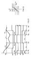
- the function of the limiter 64 is to allow the input signal I E2 to pass unchanged if it remains between two limits +l EM and -l EM (Fig. 13), otherwise it limits it to these values, if the signal GRED is at zero level. If, on the other hand, the signal GRED is at one level, the limits are +l' EM and -I' EM . In this way, by operating on the signal GRED, it is possible to vary the current gain for the position loop.
- the motor 29 to be controlled is at a standstill and that, on the basis of the input data of the channel 49 (Fig. 3), it must carry out a rotation corresponding to six and a half increments.
- the microprocessor 40 establishes the values of h R , T s and h s .
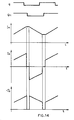
- the microprocessor 40 bringing the signal M2 to zero level and the signal M3 to one level, effects the starting of the motor 29, giving it a forward command corresponding to an acceleration. This state is maintained up to the instant F,, corresponding to the leading edge B, of the signal STB (Fig. 11).
- this step pa is still equal to one increment.
- the microprocessor 40 maintains the signal M3 at one level and the signals M1 and M2 at zero level for the time Q necessary to the microprocessor for effecting its calculations (Fig. 7), thus continuing to accelerate the motor 29.
- the time Q having elapsed, the motor is still kept accelerated for a forcing time where h R1 is the proportionality constant associated with the time T R1 and T Po is the predetermined fictitious time.
- the forcing corresponds to an acceleration since the fictitious time Tp o of covering of the preceding step is greater than the ideal time T R1 .
- the signal M2 is brought to one level and the motor is short-circuited until the end of the time T R1 .
- the signal M2 returns to zero level and the motor accelerates again until the end of the step pa, corresponding to a new leading edge B 2 of the signal STB at the instant F 2 .
- the microprocessor 40 maintains the motor in the state of acceleration for a further time Q starting from the instant F2, after which it forces the motor for a further forcing time
- h R2 is the proportionality constant associated with T R2
- the latter is the reference or theoretical time relating to the step in progress or current step
- T P1 is the actual time taken to cover the preceding step. Since T R2 is smaller than T P , during the forcing time the motor is accelerated, after which the signal M2 goes to one level and the motor is thus short-circuited until the end of the time T R2 and then again accelerated up to a new leading edge B 3 of the signal STB.
- N still being less than or equal to N 4
- the reference time T R is still equal to T 4 . Therefore, T R , and T R2 are equal, as are also the proportionality constants h R1 and h RZ .
- the microprocessor 40 which after each step covered updates the calculation parameters on the basis of the running table of Figure 6, now detects that N is between N 3 and N 4 , because of which the reference time T R is set equal to T 3 , while the step pa remains equal to the period pe of the signal FTA.
- the motor 29 (30,32) is braked for the whole of the time Tp 3 , bringing the signal M1 to one level, after which it is short-circuited until the end of the step, that is up to a new leading edge B 4 of the signal STB, bringing the signal M1 back to zero level and the signal M2 to one level.
- the microprocessor 40 provides for the updating of the variables; in this instance, however, N still being between N 3 and N 4 , both T R and pa remain equal to the values of the preceding step.
- the theoretical time TR 4 being also greater in this phase than the time Tp 3 of covering of the preceding step, the motor 29 (30, 32) is braked for the whole of the time T F4 , after which it is short-circuited until the end of the step, that is up to a new leading edge B 5 of the signal STB.
- the theoretical time T R5 in this phase being greater than one half of the time T P4 of covering of the preceding step, the motor 29 (30, 32) is braked for the time T F5 and the short-circuited until the end of the step, that it up to the trailing edge B 6 of the signal STB.
- step pa is one quarter of the period pe; it is for the same reason that the time T P6 which relates to the time of the covering of the preceding half period is halved in the comparison with the theoretical time T R7 of covering of a quarter period.
- the microprocessor 40 does not modify the variables.
- the current source 62 (Fig. 10) is disabled, the signal SAT being at zero level, and at the sum node 307 there arrives the limited error signal l EL .
- the signal l EO proportion to the signal l EO , which in turn indicates the position error of the motor with respect to the point of arrest X n .
- the closed loop formed by the modulator 61 (Fig. 9), the decoder 60, the driver 42, the motor 29, the resistor R s and the reconstructor 63 imposes on the motor a current l M proportional to the signal l EL .
- the motor 29 reacts with a torque which tends to bring it into the position of stable equilibrium.
- the microprocessor 40 still forces the motor 29 into braking, in a manner similar to that seen for the other steps, for a time T E , which is the time of stay of the motor 29 (30, 32) in the outside region of the zone of monotony considered and comprised between the edges B 10 and B' 10 of the same signal STB.
- edges B 10 and B' 10 are generated at instants F 11 and F 12 different from one another, there corresponds to these edges the same angular position of the motor, the latter having reversed its direction of rotation in the position C inasmuch as the forcing into braking, which is nothing other than a reversing command has been such as to cause it to reverse its rotation.
- the arrangement 20 comprises means 35 (36, 37) for generating electric signals FTA, STA and STB indicating the angular position of the motor 29 (30, 32) and the actual time Tp of covering a predetermined unitary angular distance pa, an electric control circuit 41 adapted to condition the motor 29 (30, 32) to short-circuit it, brake it or accelerate it, and a microprocessor 40 connected to the circuit 41 and to the signal generator 35 (36, 37), and that in the microprocessor 40 there are stored the theoretical times T R for covering each unitary distance pa as a function of the full amplitude of the rotation that the motor must effect, and that the microprocessor 40 is adapted to compare the actual times Tp with the theoretical times T R for covering each unitary distance pa to determine in what state the circuit 41 must keep the motor 29 (30, 32) and the time of duration of each state.
- references to storing quantities in the microprocessor include the possibility of storage in memory external to the processor chip itself.
- the running table for example may be stored in internal or external ROM.
Landscapes
- Engineering & Computer Science (AREA)
- Power Engineering (AREA)
- Human Computer Interaction (AREA)
- Manufacturing & Machinery (AREA)
- Physics & Mathematics (AREA)
- General Physics & Mathematics (AREA)
- Automation & Control Theory (AREA)
- Control Of Electric Motors In General (AREA)
- Control Of Stepping Motors (AREA)
- Control Of Motors That Do Not Use Commutators (AREA)
Claims (17)
Applications Claiming Priority (2)
| Application Number | Priority Date | Filing Date | Title |
|---|---|---|---|
| IT68062/82A IT1156505B (it) | 1982-09-01 | 1982-09-01 | Dispositivo per controllare la velocita ed il posizionamento di un motore elettrico |
| IT6806282 | 1982-09-01 |
Publications (3)
| Publication Number | Publication Date |
|---|---|
| EP0102248A2 EP0102248A2 (fr) | 1984-03-07 |
| EP0102248A3 EP0102248A3 (en) | 1985-05-15 |
| EP0102248B1 true EP0102248B1 (fr) | 1988-06-01 |
Family
ID=11307567
Family Applications (1)
| Application Number | Title | Priority Date | Filing Date |
|---|---|---|---|
| EP83305020A Expired EP0102248B1 (fr) | 1982-09-01 | 1983-08-31 | Dispositif pour commander la vitesse et la position d'un moteur électrique |
Country Status (4)
| Country | Link |
|---|---|
| US (1) | US4605887A (fr) |
| EP (1) | EP0102248B1 (fr) |
| DE (1) | DE3376891D1 (fr) |
| IT (1) | IT1156505B (fr) |
Families Citing this family (17)
| Publication number | Priority date | Publication date | Assignee | Title |
|---|---|---|---|---|
| US4506321A (en) * | 1982-09-08 | 1985-03-19 | Imec Corporation | Motion control system with adaptive deceleration |
| US4689528A (en) * | 1984-10-31 | 1987-08-25 | Canon Kabushiki Kaisha | Printer |
| IT1180106B (it) * | 1984-11-05 | 1987-09-23 | Olivetti & Co Spa | Circuito per il pilotaggio dei motori elettrici di selezione tabulazione ed interlinea di una macchina per scrivere elettronica |
| US4656403A (en) * | 1985-03-21 | 1987-04-07 | Siemens Aktiengensellschaft | Digital speed control circuit for a DC motor |
| IT1199878B (it) * | 1985-04-22 | 1989-01-05 | Olivetti & Co Spa | Organo portacaratteri girevole e suo dispositivo di selezione per un unita di stampa di macchine scriventi |
| US4891764A (en) * | 1985-12-06 | 1990-01-02 | Tensor Development Inc. | Program controlled force measurement and control system |
| JPH0646367B2 (ja) * | 1986-09-29 | 1994-06-15 | 株式会社エスジ− | 位置決め制御における進み角補償方式 |
| US4808895A (en) * | 1987-11-30 | 1989-02-28 | Toshiba Machine Co., Ltd. | Acceleration control apparatus |
| DE3828638C1 (fr) * | 1988-08-24 | 1989-07-27 | Heidelberger Druckmaschinen Ag, 6900 Heidelberg, De | |
| JPH02137955A (ja) * | 1988-11-18 | 1990-05-28 | Seiko Epson Corp | プリンタ制御方法 |
| US4939440A (en) * | 1989-12-04 | 1990-07-03 | Tektronix, Inc. | Friction-compensating mass motion controller |
| US5420778A (en) * | 1990-08-09 | 1995-05-30 | System Homes Company, Ltd. | Independent real time control of output frequency and voltage of PWM inverter |
| KR940001751B1 (ko) * | 1991-09-27 | 1994-03-05 | 주식회사 금성사 | 영상기기용 카셋트 테이프의 로딩 장치 및 방법 |
| US6158857A (en) * | 1999-04-29 | 2000-12-12 | Hewlett-Packard Company | Internal drum communication using a capacitor |
| US6538406B1 (en) * | 2000-10-31 | 2003-03-25 | General Electric Co. | System and method for improving transient speed response of electric motors |
| JP3969590B2 (ja) * | 2004-05-27 | 2007-09-05 | ローム株式会社 | コイル負荷駆動回路及び光ディスク装置 |
| CN112406333B (zh) * | 2020-11-20 | 2022-06-10 | 厦门喵宝科技有限公司 | 一种微型热敏打印机控制方法 |
Family Cites Families (11)
| Publication number | Priority date | Publication date | Assignee | Title |
|---|---|---|---|---|
| US3621216A (en) * | 1969-06-30 | 1971-11-16 | Ibm | Linear interpolator |
| FR2098524A5 (fr) * | 1970-07-17 | 1972-03-10 | Thomson Csf | |
| GB1487557A (en) * | 1973-11-17 | 1977-10-05 | Masson Scott Thrissell Eng Ltd | Machine drive systems |
| JPS5287774A (en) * | 1976-01-16 | 1977-07-22 | Toyota Motor Corp | Feed control device for machine tools |
| US4103216A (en) * | 1976-05-28 | 1978-07-25 | Tally Corporation | Stepping motor closed loop constant velocity control system |
| JPS54123673A (en) * | 1978-03-16 | 1979-09-26 | Fanuc Ltd | Positioning control system |
| CH636787A5 (de) * | 1978-12-04 | 1983-06-30 | Max Hetzel | Elektronisch gesteuerte gewindeschneidmaschine. |
| US4280182A (en) * | 1979-05-14 | 1981-07-21 | John Mickowski | Microcomputer control system |
| US4366424A (en) * | 1979-05-23 | 1982-12-28 | Mckechnie Robert E | Method and apparatus for programming and operating a machine tool |
| US4312033A (en) * | 1979-07-31 | 1982-01-19 | Sweeney James S | Digital motor control for positioning system |
| AT379477B (de) * | 1979-09-20 | 1986-01-10 | Quick Rotan Elektromotoren | Drehzahlregeleinrichtung fuer eine naehmaschinenantriebsvorrichtung mit nadelpositioniereinrichtung |
-
1982
- 1982-09-01 IT IT68062/82A patent/IT1156505B/it active
-
1983
- 1983-08-31 EP EP83305020A patent/EP0102248B1/fr not_active Expired
- 1983-08-31 DE DE8383305020T patent/DE3376891D1/de not_active Expired
- 1983-09-01 US US06/528,655 patent/US4605887A/en not_active Expired - Fee Related
Also Published As
| Publication number | Publication date |
|---|---|
| EP0102248A2 (fr) | 1984-03-07 |
| IT8268062A0 (it) | 1982-09-01 |
| IT8268062A1 (it) | 1984-03-01 |
| DE3376891D1 (en) | 1988-07-07 |
| IT1156505B (it) | 1987-02-04 |
| EP0102248A3 (en) | 1985-05-15 |
| US4605887A (en) | 1986-08-12 |
Similar Documents
| Publication | Publication Date | Title |
|---|---|---|
| US4605887A (en) | Arrangement for controlling the speed and positioning of an electric motor | |
| US4091294A (en) | A.C. motor control apparatus and method | |
| GB1187709A (en) | Improvements in or relating to Slip Frequency Control of an Asynchronous Electrical Machine | |
| US5006770A (en) | Servomotor velocity control apparatus | |
| US4170155A (en) | Rotary cutter for successively cutting moving material to lengths | |
| CA1096438A (fr) | Circuit de commande pour moteur pas-a-pas | |
| US4263537A (en) | Controlled positioning of a motor shaft | |
| US4486693A (en) | Motor velocity control | |
| JPS63198585A (ja) | 速度制御サ−ボモ−タ | |
| US6812668B2 (en) | Apparatus, method and program for controlling an electric motor | |
| EP0661613B1 (fr) | Servomoteur avec régulation de vitesse tabulée dans la boucle de rétroaction | |
| US5367236A (en) | DC motor stall-detection system | |
| JPS641803B2 (fr) | ||
| US4477757A (en) | Phase commutator for closed loop control of a stepping motor | |
| US4028599A (en) | Method of controlling an A.C. motor | |
| US4570110A (en) | Programmable servo motor speed control apparatus | |
| US4554492A (en) | Motor control system | |
| US3932796A (en) | Control system for producing multi-axis contour movement for a stepping motor drive | |
| EP0287684B1 (fr) | Systeme de commande a reaction negative | |
| EP0401757A2 (fr) | Procédé de mesure de la vitesse de rotation | |
| EP0028139B1 (fr) | Machine à coudre | |
| US4151448A (en) | Pulse motor driving system | |
| US3986088A (en) | A. C. motor control apparatus and method | |
| US4254370A (en) | Closed loop positioner for a stepping motor driven by a buffered translator | |
| JPH0632579B2 (ja) | 直流モータの速度及び位置決め制御装置 |
Legal Events
| Date | Code | Title | Description |
|---|---|---|---|
| PUAI | Public reference made under article 153(3) epc to a published international application that has entered the european phase |
Free format text: ORIGINAL CODE: 0009012 |
|
| AK | Designated contracting states |
Designated state(s): DE FR GB |
|
| PUAL | Search report despatched |
Free format text: ORIGINAL CODE: 0009013 |
|
| AK | Designated contracting states |
Designated state(s): DE FR GB |
|
| 17P | Request for examination filed |
Effective date: 19851111 |
|
| 17Q | First examination report despatched |
Effective date: 19870714 |
|
| GRAA | (expected) grant |
Free format text: ORIGINAL CODE: 0009210 |
|
| AK | Designated contracting states |
Kind code of ref document: B1 Designated state(s): DE FR GB |
|
| REF | Corresponds to: |
Ref document number: 3376891 Country of ref document: DE Date of ref document: 19880707 |
|
| ET | Fr: translation filed | ||
| PLBE | No opposition filed within time limit |
Free format text: ORIGINAL CODE: 0009261 |
|
| STAA | Information on the status of an ep patent application or granted ep patent |
Free format text: STATUS: NO OPPOSITION FILED WITHIN TIME LIMIT |
|
| 26N | No opposition filed | ||
| PGFP | Annual fee paid to national office [announced via postgrant information from national office to epo] |
Ref country code: DE Payment date: 19950828 Year of fee payment: 13 |
|
| PG25 | Lapsed in a contracting state [announced via postgrant information from national office to epo] |
Ref country code: DE Effective date: 19970501 |
|
| PGFP | Annual fee paid to national office [announced via postgrant information from national office to epo] |
Ref country code: FR Payment date: 19980814 Year of fee payment: 16 |
|
| PG25 | Lapsed in a contracting state [announced via postgrant information from national office to epo] |
Ref country code: FR Free format text: LAPSE BECAUSE OF NON-PAYMENT OF DUE FEES Effective date: 20000428 |
|
| REG | Reference to a national code |
Ref country code: FR Ref legal event code: ST |
|
| REG | Reference to a national code |
Ref country code: GB Ref legal event code: IF02 |
|
| PGFP | Annual fee paid to national office [announced via postgrant information from national office to epo] |
Ref country code: GB Payment date: 20020828 Year of fee payment: 20 |
|
| PG25 | Lapsed in a contracting state [announced via postgrant information from national office to epo] |
Ref country code: GB Free format text: LAPSE BECAUSE OF EXPIRATION OF PROTECTION Effective date: 20030830 |
|
| REG | Reference to a national code |
Ref country code: GB Ref legal event code: PE20 |