EP0102315A2 - Agencement d'un circuit pour la régulation de la température de fonctionnement de l'élément chauffant d'un appareil électrique de soudure notamment d'un fer à souder - Google Patents
Agencement d'un circuit pour la régulation de la température de fonctionnement de l'élément chauffant d'un appareil électrique de soudure notamment d'un fer à souder Download PDFInfo
- Publication number
- EP0102315A2 EP0102315A2 EP83730029A EP83730029A EP0102315A2 EP 0102315 A2 EP0102315 A2 EP 0102315A2 EP 83730029 A EP83730029 A EP 83730029A EP 83730029 A EP83730029 A EP 83730029A EP 0102315 A2 EP0102315 A2 EP 0102315A2
- Authority
- EP
- European Patent Office
- Prior art keywords
- voltage
- circuit
- heating
- radiator
- switching element
- Prior art date
- Legal status (The legal status is an assumption and is not a legal conclusion. Google has not performed a legal analysis and makes no representation as to the accuracy of the status listed.)
- Granted
Links
Images

Classifications
-
- G—PHYSICS
- G05—CONTROLLING; REGULATING
- G05D—SYSTEMS FOR CONTROLLING OR REGULATING NON-ELECTRIC VARIABLES
- G05D23/00—Control of temperature
- G05D23/19—Control of temperature characterised by the use of electric means
- G05D23/20—Control of temperature characterised by the use of electric means with sensing elements having variation of electric or magnetic properties with change of temperature
- G05D23/24—Control of temperature characterised by the use of electric means with sensing elements having variation of electric or magnetic properties with change of temperature the sensing element having a resistance varying with temperature, e.g. a thermistor
- G05D23/2401—Control of temperature characterised by the use of electric means with sensing elements having variation of electric or magnetic properties with change of temperature the sensing element having a resistance varying with temperature, e.g. a thermistor using a heating element as a sensing element
-
- B—PERFORMING OPERATIONS; TRANSPORTING
- B23—MACHINE TOOLS; METAL-WORKING NOT OTHERWISE PROVIDED FOR
- B23K—SOLDERING OR UNSOLDERING; WELDING; CLADDING OR PLATING BY SOLDERING OR WELDING; CUTTING BY APPLYING HEAT LOCALLY, e.g. FLAME CUTTING; WORKING BY LASER BEAM
- B23K3/00—Tools, devices or special appurtenances for soldering, e.g. brazing, or unsoldering, not specially adapted for particular methods
- B23K3/02—Soldering irons; Bits
- B23K3/03—Soldering irons; Bits electrically heated
- B23K3/033—Soldering irons; Bits electrically heated comprising means for controlling or selecting the temperature or power
Definitions
- the invention relates to a circuit arrangement for regulating the operating temperature of the radiator of an electrical soldering device, in particular a soldering iron
- thermocouple in the soldering tip and thus in the area of the radiator, which serves as a heat sensor of the radiator used, which consists of a heating coil in the prior art mentioned.
- thermocouple requires increased mechanical additional effort in the manufacture of the soldering tip or the soldering iron itself.
- the invention has for its object to provide a circuit arrangement for controlling the operating temperature of the radiator of an electrical soldering device with the smallest possible circuitry structure, the arrangement of a heat sensor in. Area of the soldering tip or the radiator of the soldering iron should be avoided.
- the circuit arrangement according to the invention can be produced with little technical effort. In particular, this does not require a heat sensor in the area of the soldering tip or the radiator of the electrical soldering device. According to the invention, only a measuring resistor and a TRIAC switching element are switched into the heating circuit of the radiator. The TRIAC switching element is connected in particular depending on the voltage drop across the measuring resistor
- a heating coil or a ceramic heating element can serve as the heating element. It is essential that the radiator has a PTC behavior or possibly also an NTC behavior.
- the radiator to be used according to the invention has a cold / hot Ratio of, for example, 4: 1, whereas conventionally used radiators, for example in the case of soldering irons, have such a ratio of 1: 1, ie have no measurable temperature coefficient.
- the circuit arrangement carries out a constant switching between measuring and heating, the existing radiator simultaneously as. Temperature measuring element is used, i.e. the radiator is used twice
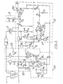
- FIG. 1 shows a heating circuit series connection from the secondary side of a power transformer 1 for the voltage supply, from a heating winding 2 - an electric soldering iron, not shown, the heating winding 2 having a PTC behavior, from a switching element designed as a TRIAC 3 and from a measuring resistor 4.
- a rectifier circuit 10, a zero-point detection circuit 20, a pulse generation circuit 30, a control amplifier circuit 40 with a diode D 4 and an integration capacitor C 5 and a comparator circuit 50 are linked to the heating circuit in the manner shown in FIG. 1.
- a potentiometer 5 for setting the temperature of the heating winding 2 is connected between the heating circuit and the control amplifier circuit 40.
- a voltage divider 6 comprising two resistors R 9 and R 10 connected in series is connected between the output of the rectifier circuit 10 and the heating circuit and is connected to the circuit 40 between the two resistors R 9 , R 10 .
- the operating voltage U 10 for the circuits 30, 40 and 50, which each contain an IC element, and the comparison voltage U 3 , which is present at the non-inverting input of the comparator circuit 50, are defined here.
- the pulse generation circuit 30 begins to emit high-frequency pulses every 1/4 second. These are synchronized by the zero point detection circuit 20 with the zero crossing of the AC voltage .
- the approximately 5 ms long pulses reach the OR input of the comparator 50, which then controls the TRIAC switching element 3 and switches it through for the positive half wave of the AC voltage.
- a voltage drop U 4 arises at the measuring resistor 4 . This is compared with the voltage u 5 on the temperature setting of the heating winding 2 potentiometer 5 and the preset voltage U 6 at the voltage divider 6, which is derived from the unregulated operating voltage U 10 , in the control amplifier circuit 40. As soon as the voltage drop U 4 across the measuring resistor 4 exceeds the preset voltage U 6 , the control amplifier circuit 40 charges the capacitor C 5 ", which forms a timing element, via the diode D 4. This voltage U 40 exceeds the voltage present at the non-inverting input of the comparator 50 Comparative voltage U 3 , the comparator 50 and also the TRIAC switching element 3 remain switched through. Consequently, the voltage supply for the heating element 2 is maintained, so that the heating element 2 remains switched on.
- the control amplifier circuit 40 switches off again.
- the capacitor C 5 is discharged via a high-resistance resistor R18 connected in parallel.
- the TRIAC switching element 3 As soon as the voltage U 40 on the capacitor C 5 drops below the comparison voltage U 3 of the comparator 50, this switches the TRIAC switching element 3 off again.
- the result of this is that the heating winding 2 of the soldering iron is also switched off.
- the timing element formed by the integration capacitor C 5 creates a certain hysteresis, which allows the heating winding 2 of the soldering iron to reheat somewhat. This means that the set end temperature is reached more quickly.
- circuits 10, 20, 30, 40 and 50 are each shown in fields separated by dashed lines.
- the rectifier circuit 10 shown immediately following the mains transformer 1 contains in a circuit connected in parallel to the secondary side of the mains transformer 1 a resistor R 1 , a diode D 1 , a further resistor R 4 and a resistor connected in reverse to the diode D 1 further diode D 6 , to which two capacitors -C 1 and C 2 are connected in parallel.
- the comparison voltage U 3 supplied to the non-inverting input 51 of the comparator circuit 50 is tapped between the resistor R 4 and the diode D 6 .
- the zero point detection circuit 20 comprises an IC element 25, ni input 21 via a resistor R 2 with the heating circuit between the secondary side of the mains transformer 1 and the heating winding 2 and its inv. Input 22 is directly linked to the heating circuit.
- a resistor R 3 is connected between the resistor R 2 and the input 21 and connected to the heating circuit.
- the output 23 of the IC element 25 is connected to the pulse generator circuit 30 via a capacitor C 4 .
- the pulse generator circuit 30 includes an IC element 35, the inputs 31 and 32 via a capacitor C 3 and a counter stood R 5 with the linked outputs of the resistor R4 of the diode D 6 and the capacitor C 2 of the rectifier circuit 10 are connected. Between the input 32 and the resistor R 5 , the capacitor C 4 of the zero point detection circuit 20 and a further resistor R 8 are connected, which is connected to the output 33 of the IC element 35. In parallel with the connection between the inputs and outputs 31 and 33 there is a further resistor R 7 , to which a series circuit comprising the resistor R 6 and the diode D 2 is connected. The output 33 of the IC element 35 leads via a diode D 3 to the inverting input 52 of the IC element 55 of the comparator circuit 50.
- the control amplifier circuit 40 comprises an IC element 45, whose inv. Input 41 is connected between the resistors R 9 and R 10 of the voltage divider 6.
- the ni input 42 is connected via a resistor R 17 to the tap of the resistor R 1 of the potentiometer 5 for temperature adjustment and via the high-resistance resistor R 18 to the connecting line to the input 52 of the IC element 55 of the comparator circuit 50.
- the output 43 of the IC element 45 is also connected to the input 52 of the IC element 55 of the circuit 50 via two series-connected, reverse-blocking diodes D 4 and D 5 .
- the integration capacitor C 5 is connected between the two diodes D 4 and D 5 , the other connection of which is connected to the heating circuit.
- a resistor R16 is connected between the resistor R 15 of the potentiometer 5 and the heating circuit.
- the IC element 55 of the comparator circuit 50, at the non-inv. Input 51, the comparison voltage U 3 is present and its inv. Input 52 via the reverse blocking diodes D 5 and D 4 with the output 43 of the IC element 45 of the control amplifier circuit 40 and at the same time via the reverse reverse blocking diode D 3 with the output 33 of the IC element 35 of the pulse generator circuit is connected to its output 53 via a resistor R 14 to the base of a transistor T 1 , the emitter of which is connected to the heating circuit and the collector of which is connected to an input of the TRIAC switching element 3, the other input of which the measuring resistor 4 (resistor R 13 ) is connected to the heating circuit.
- the output of the TRIAC switching element 3 is connected directly to the heating element 2.
- a resistor R 12 is connected 13 to preset the is provided by the resistor R 15 Potentiometers5 formed .Finally, the collector of the transistor T 1 via a resistor R 11 to both the resistor R9 of the voltage divider 6 as well as linked to the rectifier circuit 10 between the diode D 1 , the capacitor C 1 and the resistor R 4 .
- a light emitting diode D 7 for indicating the operating state is also connected to the output 53 of the IC element 55 of the comparator circuit 50 via a resistor R 19 (circuit 8).
Landscapes
- Engineering & Computer Science (AREA)
- Physics & Mathematics (AREA)
- General Physics & Mathematics (AREA)
- Automation & Control Theory (AREA)
- Mechanical Engineering (AREA)
- Control Of Resistance Heating (AREA)
- Investigating Or Analyzing Materials Using Thermal Means (AREA)
- Electric Connection Of Electric Components To Printed Circuits (AREA)
Priority Applications (1)
| Application Number | Priority Date | Filing Date | Title |
|---|---|---|---|
| AT83730029T ATE36082T1 (de) | 1982-07-28 | 1983-03-16 | Schaltungsanordnung zur regelung der betriebstemperatur des heizkoerpers eines elektrischen loetgeraetes, insbesondere loetkolbens. |
Applications Claiming Priority (2)
| Application Number | Priority Date | Filing Date | Title |
|---|---|---|---|
| DE3228202 | 1982-07-28 | ||
| DE3228202A DE3228202C2 (de) | 1982-07-28 | 1982-07-28 | Schaltungsanordnung zur Regelung der Betriebstemperatur des Heizkörpers eines elektrischen Lötgerätes, insbesondere Lötkolbens |
Publications (3)
| Publication Number | Publication Date |
|---|---|
| EP0102315A2 true EP0102315A2 (fr) | 1984-03-07 |
| EP0102315A3 EP0102315A3 (en) | 1985-01-16 |
| EP0102315B1 EP0102315B1 (fr) | 1988-07-27 |
Family
ID=6169534
Family Applications (1)
| Application Number | Title | Priority Date | Filing Date |
|---|---|---|---|
| EP83730029A Expired EP0102315B1 (fr) | 1982-07-28 | 1983-03-16 | Agencement d'un circuit pour la régulation de la température de fonctionnement de l'élément chauffant d'un appareil électrique de soudure notamment d'un fer à souder |
Country Status (6)
| Country | Link |
|---|---|
| US (1) | US4590363A (fr) |
| EP (1) | EP0102315B1 (fr) |
| AT (1) | ATE36082T1 (fr) |
| DE (1) | DE3228202C2 (fr) |
| HU (1) | HU185837B (fr) |
| IN (1) | IN158272B (fr) |
Cited By (4)
| Publication number | Priority date | Publication date | Assignee | Title |
|---|---|---|---|---|
| WO1988003455A1 (fr) * | 1986-11-05 | 1988-05-19 | Giovanni Santoro | Fer a souder conçu en particulier pour le soudage a l'etain, le soudage a l'argent et analogue |
| EP0202401A3 (en) * | 1985-04-17 | 1988-08-10 | Cooper Industries Inc. | Heating device |
| GB2207261A (en) * | 1987-06-16 | 1989-01-25 | South Of Scotland Electricity | Temperature control circuit |
| EP0337065A1 (fr) * | 1988-04-12 | 1989-10-18 | ERSA Ernst Sachs KG GmbH & Co. | Méthode et dispositif de fonctionnement pour un poste de soudure |
Families Citing this family (30)
| Publication number | Priority date | Publication date | Assignee | Title |
|---|---|---|---|---|
| US5516876A (en) | 1983-09-27 | 1996-05-14 | The Boeing Company | Polyimide oligomers and blends |
| US5714566A (en) | 1981-11-13 | 1998-02-03 | The Boeing Company | Method for making multiple chemically functional oligomers |
| US5969079A (en) | 1985-09-05 | 1999-10-19 | The Boeing Company | Oligomers with multiple chemically functional end caps |
| US5693741A (en) | 1988-03-15 | 1997-12-02 | The Boeing Company | Liquid molding compounds |
| US5705598A (en) | 1985-04-23 | 1998-01-06 | The Boeing Company | Polyester sulfone oligomers and blends |
| US5210213A (en) | 1983-06-17 | 1993-05-11 | The Boeing Company | Dimensional, crosslinkable oligomers |
| US5512676A (en) | 1987-09-03 | 1996-04-30 | The Boeing Company | Extended amideimide hub for multidimensional oligomers |
| US5618907A (en) | 1985-04-23 | 1997-04-08 | The Boeing Company | Thallium catalyzed multidimensional ester oligomers |
| US4695709A (en) * | 1986-05-01 | 1987-09-22 | The Research Foundation Of State University Of New York | Method and apparatus for heating and controlling the temperature of ultra small volumes |
| DE3704534C1 (de) * | 1987-02-13 | 1988-10-27 | Bert Dr-Ing Kueppers | Schaltungsanordnung fuer temperaturabhaengige Heizelemente |
| US4901506A (en) * | 1987-03-30 | 1990-02-20 | Automated Packaging Systems, Inc. | Heat seal temperature control |
| DE3738155A1 (de) * | 1987-11-10 | 1989-05-18 | Zeva Gmbh | Loetvorrichtung, bestehend aus mindestens einem loetkolben |
| US5817744A (en) | 1988-03-14 | 1998-10-06 | The Boeing Company | Phenylethynyl capped imides |
| US5043560A (en) * | 1989-09-29 | 1991-08-27 | Masreliez C Johan | Temperature control of a heated probe |
| US5130640A (en) * | 1990-06-28 | 1992-07-14 | Tegam, Inc. | Soldering iron testing apparatus |
| EP0489462B1 (fr) * | 1990-12-03 | 1996-06-12 | Koninklijke Philips Electronics N.V. | Système amélioré pour commande de déclenchement d'un triac en combinaison avec un détecteur |
| US5397874A (en) * | 1991-08-26 | 1995-03-14 | Edsyn, Inc. | Electric automatic temperature control |
| EP0745919A1 (fr) | 1995-05-30 | 1996-12-04 | Koch, Volker | Procédé de régulation de température d'un élément chauffant |
| US5554838A (en) * | 1995-08-23 | 1996-09-10 | Wind Lock Corporation | Hand-held heating tool with improved heat control |
| AUPO043896A0 (en) * | 1996-06-13 | 1996-07-04 | Philips Electronics Australia Limited | Circuit arrangement for controlling a heating element |
| US6946623B2 (en) * | 2000-09-15 | 2005-09-20 | Powerpulse Technologies, L.P. | Appliance for liquefying solder with variable duty cycle and method of implementing |
| DE10209436A1 (de) * | 2001-03-07 | 2002-09-19 | Helmut Prager | Vorrichtung zum Erfassen, Überwachen und Beeinflussen des Betriebszustands eines elektrischen Bügeleisens |
| US6621254B1 (en) * | 2002-04-09 | 2003-09-16 | Darrell Allen Williams | AC voltage triac regulator |
| US20060076344A1 (en) * | 2004-10-13 | 2006-04-13 | Mobiletron Electronics Co., Ltd. | Self temperature control protection heater |
| CN100431762C (zh) * | 2005-06-24 | 2008-11-12 | 深圳斯贝克动力电子有限公司 | 电烙铁温度快速补偿方法及可快速进行温度补偿的电烙铁 |
| CN1991654B (zh) * | 2005-12-31 | 2013-05-22 | 博奥生物有限公司 | 不需要温度传感器的精密加热温度控制装置及方法 |
| US7699208B2 (en) | 2007-11-30 | 2010-04-20 | Nordson Corporation | Soldering tip, soldering iron, and soldering system |
| CN112747832B (zh) * | 2020-12-24 | 2022-04-12 | 华中科技大学 | 一种制热和自馈温融合型传感器及其应用 |
| CN114326504B (zh) * | 2021-12-28 | 2024-03-26 | 深圳市和田古德自动化设备有限公司 | 一种电子产品焊锡设备智能控制系统 |
| CN115103468B (zh) * | 2022-04-08 | 2025-04-04 | 东莞市盈聚电源有限公司 | 一种恒温电烙铁驱动电源电路 |
Citations (3)
| Publication number | Priority date | Publication date | Assignee | Title |
|---|---|---|---|---|
| US3546436A (en) | 1966-11-11 | 1970-12-08 | Walter K Holzer | Electronic heat regulation |
| US3924102A (en) | 1974-05-22 | 1975-12-02 | Nicolaas W Hanekom | Apparatus for controlling temperature |
| DE2847482A1 (de) | 1978-11-02 | 1980-05-14 | Degussa | Schnellaufheizender loetkolben |
Family Cites Families (13)
| Publication number | Priority date | Publication date | Assignee | Title |
|---|---|---|---|---|
| FR1559383A (fr) * | 1967-04-04 | 1969-03-07 | ||
| DE1615310B1 (de) * | 1967-10-14 | 1971-08-12 | Holzer Patent Ag | Regeleinrichtung fuer Heizelemente |
| DE2109470C3 (de) * | 1971-03-01 | 1979-01-11 | Royston Electronics Pty. Ltd., Doncaster, Victoria (Australien) | Elektrischer Lötkolben |
| US3745308A (en) * | 1971-07-01 | 1973-07-10 | Heinemann Electric Co | Temperature control circuits |
| US3789190A (en) * | 1972-10-17 | 1974-01-29 | A J Matlen | Temperature regulation for electrical heater |
| US3881085A (en) * | 1972-12-06 | 1975-04-29 | Xerox Corp | Fuser control circuit for copying apparatus |
| DE2506074A1 (de) * | 1975-02-13 | 1976-08-26 | Braun Ag | Anordnung zur regelung der temperatur von elektrischen lockenwicklern und frisierstaeben |
| DE2619101C3 (de) * | 1976-05-03 | 1981-03-26 | Licentia Patent-Verwaltungs-Gmbh, 60596 Frankfurt | Anordnung zum Konstanthalten der Betriebstemperatur eines elektrischen Heizleiters |
| DE2724558C3 (de) * | 1977-05-31 | 1979-12-06 | Dr. Karl Thomae Gmbh, 7950 Biberach | Thermistorschaltung für ein chirurgisches Schneid- und/oder Koagulationsinstrument |
| DE2809089A1 (de) * | 1978-03-02 | 1979-09-13 | Cooper Ind Inc | Loetwerkzeug mit temperaturregelung |
| US4243875A (en) * | 1978-11-13 | 1981-01-06 | Chang Daniel C | Temperature control for resistance heating element |
| JPS6011233B2 (ja) * | 1980-03-12 | 1985-03-23 | 株式会社ボッシュオートモーティブ システム | グロ−プラグの制御回路 |
| DE3068959D1 (en) * | 1980-09-30 | 1984-09-20 | Cooper Ind Inc | Hot-air device for desoldering, soldering, shrinking and the like |
-
1982
- 1982-07-28 DE DE3228202A patent/DE3228202C2/de not_active Expired - Lifetime
-
1983
- 1983-03-16 EP EP83730029A patent/EP0102315B1/fr not_active Expired
- 1983-03-16 AT AT83730029T patent/ATE36082T1/de not_active IP Right Cessation
- 1983-05-19 IN IN625/CAL/83A patent/IN158272B/en unknown
- 1983-05-23 US US06/497,200 patent/US4590363A/en not_active Expired - Fee Related
- 1983-07-26 HU HU832625A patent/HU185837B/hu unknown
Patent Citations (3)
| Publication number | Priority date | Publication date | Assignee | Title |
|---|---|---|---|---|
| US3546436A (en) | 1966-11-11 | 1970-12-08 | Walter K Holzer | Electronic heat regulation |
| US3924102A (en) | 1974-05-22 | 1975-12-02 | Nicolaas W Hanekom | Apparatus for controlling temperature |
| DE2847482A1 (de) | 1978-11-02 | 1980-05-14 | Degussa | Schnellaufheizender loetkolben |
Cited By (6)
| Publication number | Priority date | Publication date | Assignee | Title |
|---|---|---|---|---|
| EP0202401A3 (en) * | 1985-04-17 | 1988-08-10 | Cooper Industries Inc. | Heating device |
| WO1988003455A1 (fr) * | 1986-11-05 | 1988-05-19 | Giovanni Santoro | Fer a souder conçu en particulier pour le soudage a l'etain, le soudage a l'argent et analogue |
| US5021634A (en) * | 1986-11-05 | 1991-06-04 | Giovanni Santoro | Temperature controlled soldering iron employing a variable resistance heating element for temperature sensing |
| GB2207261A (en) * | 1987-06-16 | 1989-01-25 | South Of Scotland Electricity | Temperature control circuit |
| GB2207261B (en) * | 1987-06-16 | 1992-01-08 | South Of Scotland Electricity | Temperature control circuit |
| EP0337065A1 (fr) * | 1988-04-12 | 1989-10-18 | ERSA Ernst Sachs KG GmbH & Co. | Méthode et dispositif de fonctionnement pour un poste de soudure |
Also Published As
| Publication number | Publication date |
|---|---|
| US4590363A (en) | 1986-05-20 |
| DE3228202A1 (de) | 1984-02-02 |
| HU185837B (en) | 1985-04-28 |
| EP0102315B1 (fr) | 1988-07-27 |
| EP0102315A3 (en) | 1985-01-16 |
| IN158272B (fr) | 1986-10-11 |
| DE3228202C2 (de) | 1990-11-15 |
| ATE36082T1 (de) | 1988-08-15 |
Similar Documents
| Publication | Publication Date | Title |
|---|---|---|
| EP0102315A2 (fr) | Agencement d'un circuit pour la régulation de la température de fonctionnement de l'élément chauffant d'un appareil électrique de soudure notamment d'un fer à souder | |
| DE3038538C2 (de) | Batterieladevorrichtung | |
| DE19626101B4 (de) | Schaltungsanordnung zum Starten und Betreiben einer Hochdruckentladungslampe | |
| DE4447145A1 (de) | Verfahren und Einrichtung zur Temperaturüberwachung bei Universalmotoren | |
| DE69120220T2 (de) | Verbessertes System für Triacimpulssteuerung in Verbindung mit einem Fühler | |
| DE3522586C2 (fr) | ||
| DE69224117T2 (de) | Automatische elektronische Temperaturregelung | |
| EP0202401B1 (fr) | Elément chauffant | |
| DE102013205255B4 (de) | Digitaler Temperatursensor | |
| DE2619101B2 (de) | Anordnung zum Konstanthalten der Betriebstemperatur eines elektrischen Heizleiters | |
| DE3023304C2 (de) | Elektronischer Temperaturregler für Kühl- oder Gefriergeräte mit einem Kompressor | |
| DE1615310B1 (de) | Regeleinrichtung fuer Heizelemente | |
| DE8904733U1 (de) | Heißluftpistole | |
| DE2451281C3 (de) | Meßverstärker | |
| WO1994014232A1 (fr) | Convertisseur | |
| DE2916716C2 (fr) | ||
| DE3145512C2 (de) | Anordnung zur Steuerung der von einem Widerstand erzeugten Heizleistung | |
| DE2835893C2 (de) | Ansteuerschaltung | |
| DE3704534C1 (de) | Schaltungsanordnung fuer temperaturabhaengige Heizelemente | |
| DE3507196A1 (de) | Stromversorgungseinrichtung | |
| DE2837015C2 (de) | Elektronische Sicherheitseinrichtung und ihre Verwendung | |
| DE2605369A1 (de) | Einrichtung zur bildung von steuersignalen zur regelung elektrischer oefen | |
| DE2062713A1 (de) | Elektronische Aufladesteuerung, bestehend aus einem zentralen Steuergerät und einer Mehrzahl von mit Ladereglern ausgerüsteten Wärmespeicheröfen | |
| DE1615310C (de) | Regeleinrichtung für Heizelemente | |
| DE3912417A1 (de) | Elektronischer raumtemperaturregler |
Legal Events
| Date | Code | Title | Description |
|---|---|---|---|
| PUAI | Public reference made under article 153(3) epc to a published international application that has entered the european phase |
Free format text: ORIGINAL CODE: 0009012 |
|
| AK | Designated contracting states |
Designated state(s): AT BE CH FR IT LI NL |
|
| PUAL | Search report despatched |
Free format text: ORIGINAL CODE: 0009013 |
|
| AK | Designated contracting states |
Designated state(s): AT BE CH FR IT LI NL |
|
| 17P | Request for examination filed |
Effective date: 19850316 |
|
| 17Q | First examination report despatched |
Effective date: 19870204 |
|
| GRAA | (expected) grant |
Free format text: ORIGINAL CODE: 0009210 |
|
| AK | Designated contracting states |
Kind code of ref document: B1 Designated state(s): AT BE CH FR IT LI NL |
|
| ITF | It: translation for a ep patent filed | ||
| REF | Corresponds to: |
Ref document number: 36082 Country of ref document: AT Date of ref document: 19880815 Kind code of ref document: T |
|
| ET | Fr: translation filed | ||
| PLBI | Opposition filed |
Free format text: ORIGINAL CODE: 0009260 |
|
| 26 | Opposition filed |
Opponent name: THE COOPER GROUP DEUTSCHLAND GMBH Effective date: 19890427 |
|
| NLR1 | Nl: opposition has been filed with the epo |
Opponent name: THE COOPER GROUP DEUTSCHLAND GMBH |
|
| ITTA | It: last paid annual fee | ||
| PLBM | Termination of opposition procedure: date of legal effect published |
Free format text: ORIGINAL CODE: 0009276 |
|
| STAA | Information on the status of an ep patent application or granted ep patent |
Free format text: STATUS: OPPOSITION PROCEDURE CLOSED |
|
| 27C | Opposition proceedings terminated |
Effective date: 19911105 |
|
| PGFP | Annual fee paid to national office [announced via postgrant information from national office to epo] |
Ref country code: FR Payment date: 19930315 Year of fee payment: 11 |
|
| PGFP | Annual fee paid to national office [announced via postgrant information from national office to epo] |
Ref country code: AT Payment date: 19930330 Year of fee payment: 11 |
|
| PGFP | Annual fee paid to national office [announced via postgrant information from national office to epo] |
Ref country code: NL Payment date: 19930331 Year of fee payment: 11 |
|
| PGFP | Annual fee paid to national office [announced via postgrant information from national office to epo] |
Ref country code: BE Payment date: 19930406 Year of fee payment: 11 |
|
| PGFP | Annual fee paid to national office [announced via postgrant information from national office to epo] |
Ref country code: CH Payment date: 19930419 Year of fee payment: 11 |
|
| PG25 | Lapsed in a contracting state [announced via postgrant information from national office to epo] |
Ref country code: AT Effective date: 19940316 |
|
| PG25 | Lapsed in a contracting state [announced via postgrant information from national office to epo] |
Ref country code: LI Effective date: 19940331 Ref country code: CH Effective date: 19940331 Ref country code: BE Effective date: 19940331 |
|
| NLR2 | Nl: decision of opposition | ||
| BERE | Be: lapsed |
Owner name: ERSA ERNST SACHS K.G. G.M.B.H. & CO. Effective date: 19940331 |
|
| PG25 | Lapsed in a contracting state [announced via postgrant information from national office to epo] |
Ref country code: NL Effective date: 19941001 |
|
| NLV4 | Nl: lapsed or anulled due to non-payment of the annual fee | ||
| PG25 | Lapsed in a contracting state [announced via postgrant information from national office to epo] |
Ref country code: FR Effective date: 19941130 |
|
| REG | Reference to a national code |
Ref country code: CH Ref legal event code: PL |
|
| REG | Reference to a national code |
Ref country code: FR Ref legal event code: ST |