EP0102316A2 - Verfahren zur Herstellung von Reifen - Google Patents
Verfahren zur Herstellung von Reifen Download PDFInfo
- Publication number
- EP0102316A2 EP0102316A2 EP83730063A EP83730063A EP0102316A2 EP 0102316 A2 EP0102316 A2 EP 0102316A2 EP 83730063 A EP83730063 A EP 83730063A EP 83730063 A EP83730063 A EP 83730063A EP 0102316 A2 EP0102316 A2 EP 0102316A2
- Authority
- EP
- European Patent Office
- Prior art keywords
- detecting
- molding
- movement
- rotation
- aid
- Prior art date
- Legal status (The legal status is an assumption and is not a legal conclusion. Google has not performed a legal analysis and makes no representation as to the accuracy of the status listed.)
- Withdrawn
Links
- 238000000465 moulding Methods 0.000 title claims abstract description 94
- 238000000034 method Methods 0.000 title claims abstract description 53
- 230000008569 process Effects 0.000 claims abstract description 30
- 239000011324 bead Substances 0.000 description 27
- 238000010586 diagram Methods 0.000 description 7
- 238000010276 construction Methods 0.000 description 6
- 238000007796 conventional method Methods 0.000 description 5
- 230000000994 depressogenic effect Effects 0.000 description 5
- 239000002994 raw material Substances 0.000 description 4
- 238000004519 manufacturing process Methods 0.000 description 3
- 238000006073 displacement reaction Methods 0.000 description 2
- 230000000977 initiatory effect Effects 0.000 description 2
- 230000007257 malfunction Effects 0.000 description 2
- 238000004804 winding Methods 0.000 description 2
- 230000037303 wrinkles Effects 0.000 description 2
- 241000119744 Allium motor Species 0.000 description 1
- 230000004075 alteration Effects 0.000 description 1
- 230000008602 contraction Effects 0.000 description 1
- 238000001514 detection method Methods 0.000 description 1
- 239000002657 fibrous material Substances 0.000 description 1
- 230000007246 mechanism Effects 0.000 description 1
- 238000012986 modification Methods 0.000 description 1
- 230000004048 modification Effects 0.000 description 1
- 230000008707 rearrangement Effects 0.000 description 1
- 230000000246 remedial effect Effects 0.000 description 1
- 238000004073 vulcanization Methods 0.000 description 1
Images




Classifications
-
- B—PERFORMING OPERATIONS; TRANSPORTING
- B29—WORKING OF PLASTICS; WORKING OF SUBSTANCES IN A PLASTIC STATE IN GENERAL
- B29D—PRODUCING PARTICULAR ARTICLES FROM PLASTICS OR FROM SUBSTANCES IN A PLASTIC STATE
- B29D30/00—Producing pneumatic or solid tyres or parts thereof
- B29D30/06—Pneumatic tyres or parts thereof (e.g. produced by casting, moulding, compression moulding, injection moulding, centrifugal casting)
- B29D30/08—Building tyres
- B29D30/10—Building tyres on round cores, i.e. the shape of the core is approximately identical with the shape of the completed tyre
- B29D30/18—Fitting the bead-rings or bead-cores; Folding the textile layers around the rings or cores
-
- B—PERFORMING OPERATIONS; TRANSPORTING
- B29—WORKING OF PLASTICS; WORKING OF SUBSTANCES IN A PLASTIC STATE IN GENERAL
- B29D—PRODUCING PARTICULAR ARTICLES FROM PLASTICS OR FROM SUBSTANCES IN A PLASTIC STATE
- B29D30/00—Producing pneumatic or solid tyres or parts thereof
- B29D30/06—Pneumatic tyres or parts thereof (e.g. produced by casting, moulding, compression moulding, injection moulding, centrifugal casting)
- B29D30/08—Building tyres
-
- B—PERFORMING OPERATIONS; TRANSPORTING
- B29—WORKING OF PLASTICS; WORKING OF SUBSTANCES IN A PLASTIC STATE IN GENERAL
- B29D—PRODUCING PARTICULAR ARTICLES FROM PLASTICS OR FROM SUBSTANCES IN A PLASTIC STATE
- B29D30/00—Producing pneumatic or solid tyres or parts thereof
- B29D30/06—Pneumatic tyres or parts thereof (e.g. produced by casting, moulding, compression moulding, injection moulding, centrifugal casting)
- B29D30/08—Building tyres
- B29D30/20—Building tyres by the flat-tyre method, i.e. building on cylindrical drums
- B29D30/32—Fitting the bead-rings or bead-cores; Folding the textile layers around the rings or cores
- B29D2030/3221—Folding over means, e.g. bladders or rigid arms
- B29D2030/3257—Folding over means, e.g. bladders or rigid arms using pressing rollers
Definitions
- the present invention relates to an improved method of molding tires.
- a tire is generally manufactured by way of the steps of winding raw material therefor round a cylindrical molding drum, carrying out molding to obtain a molded product (which is usually called green tire) and then press forming said molded product in a die while subjecting it to vulcanization at an elevated temperature until a finished tire is produced.
- a molded product which is usually called green tire
- beads constituting the most essential component for assuring strength and quality of the tire structure will be described in more details with respect to a process for wrapping beads with carcass plys comprising the processes of ply-down, bead-stitch, pull-out and turn-up.
- a cylindrical molding drum la or 2a is fitted with a carcass ply lb or 2b by winding the latter round said molding drum la or 2a or preforming it in a cylindrical configuration and then thrusting the preformed one over the molding drum la or 2a.
- the overhung portion lc or 2c of the carcass ply lb or 2b is folded along the configuration of the molding drum la or 2a.
- a bead ld or 2d is then thrusted onto the overhung portion lc or 2c of the carcass ply lb or 2b and thereafter the overhung portion lc or 2c is wound up until it overlapps the carcass ply lb or 2b so that the bead ld or 2d is wrapped thereby.
- a process of wrapping a bead is completed.
- reference numeral 3 designates a stitcher tool carried by an arm 4.
- a pneumatic spring 5 attached to the lower part of the arm 4 is caused to expand, thrusting force to be exerted on the drum is transmitted to the stitcher tool 3.
- the arm 4 is turnably mounted on a bracket 6 adapted to rotate about a worm wheel 8 which meshes with a worm 9 in a carriage 7, said worm 9 being driven by means of a motor 10 via an endless chain 11 and a driving shaft 12.
- the carriage 7 is movably mounted on a platform 13 so that it moves in parallel to the axis of drum as a feed screw 14 is rotated.
- the fe.ed screw 14 is divided into two sections at the middle thereof so as to have two halves extending in the opposite direction to one another and it is driven by means of a motor 15 via an endless chain 16.
- the platform 13 is movably mounted on the base which is fixedly mounted on the floor (not shown) so that it moves in the radial direction as a feed screw 17 is rotated.
- the feed screw 17 is driven by means of a motor 18 via an endless chain 19 and a gear box 20.
- shaft end coders 21, 22 and 23 are disposed at the one end of the driving shaft 12 and the feed screws 14 and 17 so that the position and the direction of rotation of the stitcher tool 3 are detected. The above-mentioned three movements are controlled in accordance with the following conventional methods.
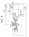
- Fig. 4 schematically illustrates this control method by way of a block diagram. To simplify illustration the stitcher tool is shown on the drawing only with respect to movement in the traverse direction. Controlling of a pull-out device is also shown on the drawing and it will be described in more details later.
- Reference numeral 30 designates a relay sequence
- reference numeral 40a does a control device for a.motor 50a which serves for driving a stitcher tool 60a in the traverse direction
- reference numeral 70a does a detecting device for detecting the traverse position of the stitcher tool 60a
- reference numeral 40b does a control device for a motor 50b which serves for driving a drum 60b
- reference numeral 70b does a detecting device for detecting rotation of the drum 60b
- reference numerals 40c and 40d do a control device for hydraulic cylinders 50c and 50d resnectively which serve for driving pull-out devices 60c and 60d
- reference numeral 50e does a hydraulic unit
- reference numerals 70c and 70d do a detecting device for detecting the position of the pull-out devices 60c and 60d resnectively
- reference numerals 80a, 80b, 80c and 80d do a process completion signal respectively.
- the above method takes long time until one sequence is prepared by way of the repeated steps of desk planning, application to practical operations and rearrangement and moreover requires a large amount of expenditure for manufacturing tires on the trial base.
- the relay sequence of the conventional method can be repeatedly employed when a considerably large lot number of tires are manufactured for truck, bus or the like vehicle, but in case of manufacturing on the base of small number and many kinds, for instance, for vehicles for construction works it is not practicable because there is necessity for rearrangment to be made at every time when the kind of tire to be manufactured is shifted to another one and therefore it is employed at substantially reduced onerational efficiency.
- Fig..6 schematically illustrates a method of controlling the stitcher tool and the drum by manual handling by way of a block diagram (it should be noted that controlling of the pull-out device is scribed on the drawing but it will be described in more details later).
- this method an operator specifies one of three movements comprising movement in the traverse direction, movement in the radial direction and rotary movement while he watches existing movement of the stitcher tool and there is no necessity for feeding back signals with respect to the position of the stitcher tool but feedback is required for controlling rotation of the drum.
- controlling is carried out by manual handling commands 90a, 90b, 90c and 90d instead of the relay sequence 80 as illustrated in Fig. 4.
- this method may be modified in such a manner as to feed back signals with res-oect to the position of the stitcher tool, but since a command is given by an operator, there is still necessity for highly trained skill and few reproductivity is assured. Moreover, fluctuation in quality of finished tires takes place unavoidably due to difference in skill of operators.
- Fig. 7 schematically illustrates an example of a large size of tire molding machine which is utilized for manufacturing tires for a vehicle for construction works or the like.
- reference numeral 101 designates a molding drum constituting an essential component for molding tires.
- the molding drum 101 is mounted on a main shaft 102 by means of a tail stock which serves to support a tail stock shaft 105 adapted to be connected to the main shaft 102.
- the tail stock shaft 105 includes a conventional means which does not inhibit rotation of the main shaft 102 caused by a driving mechanism (not shown) while the main shaft 102 is in operative connection to the tail stock shaft 105.
- Reference numeral 106 designates a stitching device which serves to thrust raw material for tire fitted onto the molding drum 101 and reference numeral 107 does a pull-out ring which is mounted on a sleeve 8 slidably fitted onto the main shaft 102.
- the sleeve 108 is adapted to slide on the main shaft 102 in the axial direction by operating a hydraulic cylinder 109 mounted on the head stock 103.
- Reference numeral 110 designates a so-called bead ring which is a conventional component fitted to mold tires.
- the bead ring 110 is mounted on a plurality of pawls 113 on a block 112 adapted to slide in the axial direction with the aid of a hydraulic cylinder 111 mounted on the head stock 103.
- the bead ring 110 on the pawls 118 is located in the proximity of raw material on the molding drum 101 at a certain time during tire molding.
- the pull-out ring 107 is divided into several pieces of sections along the periphery thereof and includes a plurality of segments 121 disposed between the adjacent divided sections, said segments 121 moving outward or inward in the radial direction.
- a sleeve 114, a pull-out ring 115, a block 116 and pawls 117 constructed in the substantially same manner as the sleeve 108, the pull-out ring 107, the block 112 and pawls 118 are mounted on the tail stock shaft 105.
- a rubber layer 118 including fibrous material therein (to serve as raw material for tire) that is called cylindrical band is fitted onto the molding drum 101 in such a manner as illustrated in the left half of Fig. 8, it is then thrusted against the molding drum 101 along the configuration of both tne end parts thereof by means of a stitcher tool 119 of the stitch device 106 (as illustrated at the upper part of the right half of the drawing) and thereafter a bead ring 110 held by means of the pawls 113 and 117 is thrusted against the rubber layer 118 (as illustrated at the lower part of the right half of the drawing).
- the pull-out rings 107 and 115 fixedly secured to the outermost end part of the sleeves 108 and 114 are caused to move outward (toward the opposite side of the molding drum 101) together with the sleeves 108 and 114 by operating hydraulic cylinders whereby the segments 121 of both the pull-out rings 107 and 115 are projected outward in the radial direction until both the side end edge parts of the rubber band 118 are deformed as illustrated at the left half of Fig. 9.
- the sleeves 108 and 114 are displaced inward (toward the inside of the molding drum 101) by a predetermined distance so that both the side end edge parts of the rubber band 118 are thrusted by means of each of the segments 121 of the pull-out rings 107 and 115 in such a manner as to encase the bead ring 110 (see the right half of Fig. 9).
- the present invention has been made with the foregoing problems in mind and its object resides in providing an improved method of molding tires free from the drawbacks inherent to the conventional methods which assures that a high quality of tire is manufactured at an excellently high operational efficiency.
- the present invention consists in that tire molding is carried out by way of the steps of detecting movement of a stitcher tool during the tire molding under manual handling with the aid of a position detecting device, detecting at least either of the number of revolutions and the direction of rotataion of a molding drum with the aid of a rotation detecting device, storing the results of detecting in a storage device and thereafter automatically controlling movement of the stitcher tool as well as at least either of the number of revolutions and the direction of rotation of the molding drum by processing signals issued from said storage device.
- the stitcher.tool and the molding drum are controlled under manual handling by way of which movement of the stitcher tool as well as the number of revolutions and the direction of rotation of the molding drum can be controlled as required, movement of the stitcher tool during tire molding under manual handling is detected by means of a position detecting device while the number of revolutions and the direction of rotation of the molding drum are detected by means of a rotation detecting device, the results of detecting are stored in a storage device and thereafter movement of the stitcher tool and rotation of the molding drum are automatically controlled by processing signals issued from the storage device.
- the present invention consists in that tire molding is carried out by way of the steps of detecting movement of a stitcher tool during the tire molding under manual handling for processes comprising turn-down, bead-stitch, turn-up and ply-lock with the aid of a position detecting device, detecting at least either of the number of revolutions and the direction of rotation of a molding drum with the aid of a rotation detecting device, detecting movement of a pull-out device under manual handling with the aid of a position detecting device prior to the turn-up process after completion of the bead-stitch process, storing the results of detecting in a storage device and thereafter automatically controlling movement of the stitcher tool, at least either of the number of revolutions and the direction of rotation of the molding drum and movement of the pull-out device by processing signals issued from said storage device.
- the stitcher tool, the molding drum and the pull-out devices disposed at both the sides of the molding drum are controlled under manual handling by way of which movement of the stitcher tool, rotation of the molding drum and operation of the pull-out devices can be controlled as required, movement of the pull-out devices during tire molding under manual handling is detected by means of a position detecting device, the results of detecting are stored in a storage device and thereafter movement of the pull-out devices are automatically controlled by processing signals issued from the storage device.
- Fig. 10 which is a block diagram schematically illustrating an embodiment of the invention a position control system for a stitcher tool is typically shown only with respect to a traverse position control system for the purpose of simplification of illustration. It should be noted that the same or substantially same components as those in the traverse position control system are provided also with respect to both radial and rotary position control systems. Same or similar parts and components as those in Figs. 4 and 6 are identified with the same reference numerals.
- Tire molding is carried out in conformance with commands issued under manual handling prepared by manual handling command devices 90a and 90b while operations of a stitcher tool 60a and a molding drum 60b are controlled.
- During tire molding operation of the stitcher tool 60a is detected by means of a position detecting device 70a and the number of revolutions and the direction of rotation of the molding drum 60b are detected by means of a rotation detecting device 70b so that the results of detecting are stored in a storage device 100 by feeding back them thereto.
- control operation is shifted to automatic control operation by actuating a shift switch.
- the stitcher tool and the molding drum can be automatically controlled in accordance with signals issued from the storage device 100 after a start button is depressed so that the same operations as those in the beginning are carried out for them.
- tire molding is also carried out in conformance with commands issued under manual handling prepared by manual handling command devices 90c and 90d while operations of a righthand pull-out device 90c and a lefthand pull-out device 60d are controlled individually thereby.
- onerations of both the pull-out devices are detected by means of position detecting devices 70c and 70d respectively and the results of detecting are stored in the storage device 100 by feeding back them to the latter.
- both the pull-out devices can be automatically controlled in accordance with signals issued from the storage device 100 after a start button is depressed so that the same operations as those in the beginning are carried out for them. It should be noted that both the pull-out devices may be controlled by stored signals only for the righthand or lefthand pull-out device in order to reduce storing capacity in the storage device.
- points P1 to P5 in Fig. 11 serve as a reference point for controlling the position for pull-out process--and an initial point PO serves as an original point for a position control device.
- the manual handling command device 90c or 90d is initiated to operate so that the pull-out ring 60c (or 60d) is displaced to the point Pl located outward of the molding drum and the point Pl is then stored in the storage device 100.
- segments constituting the pull-out ring 60c (or 60d) are caused to expand and time tl which has elapsed after issuance of a command for exnanding them is stored in the storage device 100.
- the pull-out ring 60c (or 60d) is displaced toward the molding drum until the point P2 is reached while the segments of the pull-out ring 60c (or 60d) are kept in the expanded state and the point P2 is then stored in the storage device 100.
- the pull-out ring 60c (or 60d) is displaced outward of the molding drum until the point P3 is reached.
- the segments constituting the pull-out ring 60c (or 60d) are caused to contract until the position P5 is reached and thereafter the time t3 which has elapsed until contraction is completed after initiation of the same is stored in the storage device 100.
- the point PO is then resumed and it is stored in the storage device 100.
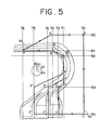
- a device 90a as illustrated in Fig. 10 with reference to Fig. 5, said device 90a being provided with a shift switch which can issue a command for initiating three movements comprising movement in the traverse direction, movement in the radial direction and rotary movement.
- interlocking is established so as to inhibit both the movements in the traverse and radial directions from being initiated during the rotary movement in the illustrated embodiment of the invention.
- actuations of the shift switch are stored in the storage device.
- the stitcher tool is located at the point 0 (as defined by lines TO and RO) and moreover it assumes the angular position as defined by line AO (during rotary movement).
- the shift switch is actuated so that the stitcher tool enters movement in the radial direction.
- a command is issued so as to intiate rotary movement.
- a value of detection achieved by the position detecting device when a command is to be altered is stored in the storage device.
- the shift switch is actuated (so as to store the position as defined by lines TO, R4 and A3) so that the position 2' (as defined by lines T2 and R4) is reached.
- the shift switch is actuated in the same manner as in the foregoing while an operator is watching movement of the stitcher tool, whereby the latter is displaced in accordance with the predermined order of position 3' ⁇ position 4' ⁇ position 5 ⁇ ( angular position A3 ⁇ angular position A2) ⁇ position 6 ⁇ ( angular position A2 ⁇ angular position A1) ⁇ position 7 4 position 8 ⁇ ( angular position A1 ⁇ angular position A0) ⁇ position 0.
- a turn-up process is completed for the third bead. It should be of cource understood that during the turn-up process the molding drum rotates and alterations intentionally made with respect to the number of revolutions and the direction of rotation of the molding drum are stored in the storage device, corresponding to movement of the stitcher tool.
- the stitcher tool When it is found that there takes place any malfunction such as occurance of wrinkles on the carcass ply, for instance, at the position 4" located midway of displacement from the point 4' to the point 5, the stitcher tool is caused to stop its movement by actuating the shift switch so as to conduct remedial activity for straightening wrinkles and thereafter the position 4" is stored in the storage device.
- a returnable push button is preferably provided and an electric circuit is designed so that storing of the position 4" is cancelled with said push button depressed and the stitcher tool resumes the previous position (position 4' in this case).
- a main shift switch is shifted to the automatic position and an automatic start button is then depressed whereby movement of the stitcher tool is automatically controlled in conformance with the data stored in the storage device and a series of processes comprising ply-down, turn-up and others are automatically carried out. It should be of cource understood that necessary interlocking should be prepared so as to assure that the stitcher tool is inhibited from further movement when it reaches the point 0 unless the automatic start button is depressed again.
- the method of the invention is constructed such that movement of the stitcher tool under manual handling as well as the number of revolutions and the direction of rotation of the molding drum are detected and stored and moreover movement of the pull-out devices is detected and stored in the storage device.
- the method of the invention has excellently high reproductivity of operation and there is no necessity for rearranging a sequence whereby a number of tires having high quality can be manufactured at an excellently high efficiency.
Landscapes
- Engineering & Computer Science (AREA)
- Mechanical Engineering (AREA)
- Tyre Moulding (AREA)
Applications Claiming Priority (2)
| Application Number | Priority Date | Filing Date | Title |
|---|---|---|---|
| JP113430/82 | 1982-06-30 | ||
| JP57113430A JPS592832A (ja) | 1982-06-30 | 1982-06-30 | タイヤ成形方法 |
Publications (2)
| Publication Number | Publication Date |
|---|---|
| EP0102316A2 true EP0102316A2 (de) | 1984-03-07 |
| EP0102316A3 EP0102316A3 (de) | 1986-03-12 |
Family
ID=14612022
Family Applications (1)
| Application Number | Title | Priority Date | Filing Date |
|---|---|---|---|
| EP83730063A Withdrawn EP0102316A3 (de) | 1982-06-30 | 1983-06-30 | Verfahren zur Herstellung von Reifen |
Country Status (2)
| Country | Link |
|---|---|
| EP (1) | EP0102316A3 (de) |
| JP (1) | JPS592832A (de) |
Cited By (2)
| Publication number | Priority date | Publication date | Assignee | Title |
|---|---|---|---|---|
| EP1537986A4 (de) * | 2002-06-14 | 2005-07-13 | Bridgestone Corp | Reifenherstellungsverfahren und einrichtung zur herstellung eines rohreifens |
| WO2009081221A1 (en) * | 2007-12-21 | 2009-07-02 | Pirelli Tyre S.P.A. | Process and plant for building tyres for vehicle wheels |
Family Cites Families (1)
| Publication number | Priority date | Publication date | Assignee | Title |
|---|---|---|---|---|
| US3524784A (en) * | 1967-01-12 | 1970-08-18 | Amk Subsidiary Corp | Tire building machine |
-
1982
- 1982-06-30 JP JP57113430A patent/JPS592832A/ja active Pending
-
1983
- 1983-06-30 EP EP83730063A patent/EP0102316A3/de not_active Withdrawn
Cited By (3)
| Publication number | Priority date | Publication date | Assignee | Title |
|---|---|---|---|---|
| EP1537986A4 (de) * | 2002-06-14 | 2005-07-13 | Bridgestone Corp | Reifenherstellungsverfahren und einrichtung zur herstellung eines rohreifens |
| US7361243B2 (en) | 2002-06-14 | 2008-04-22 | Bridgestone Corporation | Tire manufacturing method and green tire manufacturing apparatus |
| WO2009081221A1 (en) * | 2007-12-21 | 2009-07-02 | Pirelli Tyre S.P.A. | Process and plant for building tyres for vehicle wheels |
Also Published As
| Publication number | Publication date |
|---|---|
| JPS592832A (ja) | 1984-01-09 |
| EP0102316A3 (de) | 1986-03-12 |
Similar Documents
| Publication | Publication Date | Title |
|---|---|---|
| KR100447475B1 (ko) | 차량용그린타이어제조장치의조립체및그그린타이어의제조방법 | |
| US4392899A (en) | Process and apparatus for manufacturing vehicle tires | |
| EP1481791B1 (de) | Verfahren zur Reifenherstellung zur Verwendung in einem flexiblen Herstellungssystem. | |
| US6746557B2 (en) | Bead loading method and apparatus | |
| EP0995584B1 (de) | Reifenwulstwickelvorrichtung und verfahren | |
| JP3370369B2 (ja) | 車輪用タイヤの組立カーカスの製造装置 | |
| EP0313506A2 (de) | Verfahren zur Herstellung von Reifen | |
| EP1497106B1 (de) | Verfahren und anlage zur herstellung von reifenrohlingen | |
| EP0676277B1 (de) | Verfahren und Vorrichtung zur Herstellung von Radialreifen | |
| US6773530B2 (en) | Method for manufacturing tires on a flexible manufacturing system | |
| EP1765581B1 (de) | Verfahren und vorrichtung zum positionieren von wulstkernen | |
| EP0102316A2 (de) | Verfahren zur Herstellung von Reifen | |
| EP1682336B1 (de) | Anordnung von vorrichtungen zur herstellung von nicht vulkanisierten radialreifen und verfahren zur herstellung solcher reifen | |
| US2936023A (en) | Apparatus for making tire casings | |
| EP2055467A1 (de) | Wulststrukturerzeugungsvorrichtung in einer Erzeugungsmaschine für grüne Reifen | |
| EP1238788B1 (de) | Vorrichtung zur herstellung von radialreifen | |
| US3524784A (en) | Tire building machine | |
| US5215611A (en) | Method and apparatus for producing a tread/reinforcement belt unit for a pneumatic vehicle tire | |
| EP0302935B1 (de) | Radialreifen für flugzeug und dessen herstellung | |
| EP2646232B1 (de) | Verfahren, anlage und aufbautrommel zum management von aufbautrommeln in einem verfahren zur herstellung von reifen | |
| JP3817353B2 (ja) | タイヤ成形装置 | |
| KR20030057455A (ko) | 타이어 제조 방법 | |
| JP3217455B2 (ja) | タイヤ成形機におけるタイヤ構成材料の折り返し装置 | |
| SU1553402A1 (ru) | Агрегат дл сборки покрышек пневматических шин | |
| KR950000192B1 (ko) | 타이어 성형용 반제품 조립장치 |
Legal Events
| Date | Code | Title | Description |
|---|---|---|---|
| PUAI | Public reference made under article 153(3) epc to a published international application that has entered the european phase |
Free format text: ORIGINAL CODE: 0009012 |
|
| AK | Designated contracting states |
Designated state(s): DE FR GB IT NL |
|
| 17P | Request for examination filed |
Effective date: 19840207 |
|
| PUAL | Search report despatched |
Free format text: ORIGINAL CODE: 0009013 |
|
| AK | Designated contracting states |
Kind code of ref document: A3 Designated state(s): DE FR GB IT NL |
|
| 17Q | First examination report despatched |
Effective date: 19870520 |
|
| STAA | Information on the status of an ep patent application or granted ep patent |
Free format text: STATUS: THE APPLICATION IS DEEMED TO BE WITHDRAWN |
|
| 18D | Application deemed to be withdrawn |
Effective date: 19871005 |
|
| RIN1 | Information on inventor provided before grant (corrected) |
Inventor name: IRIE, NOBUHIKONAGASAKI SHIPYARD & ENGINE WORKS |