EP0102376B1 - Überwachungsverfahren für die eintrittskontrolle zu tanzhallen usw. und dessen ausführung - Google Patents
Überwachungsverfahren für die eintrittskontrolle zu tanzhallen usw. und dessen ausführung Download PDFInfo
- Publication number
- EP0102376B1 EP0102376B1 EP83900909A EP83900909A EP0102376B1 EP 0102376 B1 EP0102376 B1 EP 0102376B1 EP 83900909 A EP83900909 A EP 83900909A EP 83900909 A EP83900909 A EP 83900909A EP 0102376 B1 EP0102376 B1 EP 0102376B1
- Authority
- EP
- European Patent Office
- Prior art keywords
- admission
- unit
- marking
- recorder
- stamp
- Prior art date
- Legal status (The legal status is an assumption and is not a legal conclusion. Google has not performed a legal analysis and makes no representation as to the accuracy of the status listed.)
- Expired
Links
- 238000000034 method Methods 0.000 title claims abstract description 10
- 239000003550 marker Substances 0.000 claims abstract description 18
- 230000000903 blocking effect Effects 0.000 description 4
- 235000021170 buffet Nutrition 0.000 description 2
- 239000012530 fluid Substances 0.000 description 2
- 230000003213 activating effect Effects 0.000 description 1
- 239000003795 chemical substances by application Substances 0.000 description 1
- 239000004020 conductor Substances 0.000 description 1
- 230000006735 deficit Effects 0.000 description 1
- 230000000694 effects Effects 0.000 description 1
- 239000002184 metal Substances 0.000 description 1
- 238000004080 punching Methods 0.000 description 1
Images
Classifications
-
- G—PHYSICS
- G07—CHECKING-DEVICES
- G07C—TIME OR ATTENDANCE REGISTERS; REGISTERING OR INDICATING THE WORKING OF MACHINES; GENERATING RANDOM NUMBERS; VOTING OR LOTTERY APPARATUS; ARRANGEMENTS, SYSTEMS OR APPARATUS FOR CHECKING NOT PROVIDED FOR ELSEWHERE
- G07C9/00—Individual registration on entry or exit
- G07C9/30—Individual registration on entry or exit not involving the use of a pass
Definitions
- the present invention relates to a handheld admission order marking device for supervising the control of the admission right of persons to dancing halls and similar establishments with controlled admission, said device comprising a signal generator operable by each marking operation thereof to generate an actuator signal, which is recorded by a recorder or counter unit belonging to said device.
- Such a marking device is known from US-A-1,405,434.
- This publication discloses a railway- ticket punch.
- the punch comprises two jaws for punching or cutting out a ticket receipt and a register which is provided on the top of the jaw.
- the register records automatically the number of fares, whether cash or ticket fares are received by the conductor.
- the use of the known device for the admission control of persons with a valid admission order in the form of a ticket to dancing halls and similar establishments opens up the possibility of irregularities.
- the personnel at the entrance can manipulate with the tickets to cheat the owner or the personnel can be cheated by the guests so that the cash box shows a deficit.
- a further disadvantage of the known device in that is relatively heavy to handle due to the mechanical system and the way of receiving the receipt.
- the invention therefor provides a device of the above-mentioned kind characterized in that said marking device is constituted by a stamping unit which at least from time to time requires to be supplied with a marking agent as supplied from an associated marking agent source by a recharging operation of the stamping unit similar to said marking operation thereof, in that sensing means are provided for sensing the operation of the stamping unit as being said recharging operation, and in that said sensing means are operatively connected with said signal generator or said recorder unit so that said recharging operation can be effected without being recorded as a marking operation.
- the method according to the invention is characterized in that the marking device is caused to generate an actuator signal to a recorder unit by each marking operation thereof.
- a simple device and a safe and just method which renders it possible to supervise the admission control of guests to dancing halls and other establishments with paid admission as each order giving operation of the admission order giving device automatically may be registered in a recorder unit, e.g. at the entrance or in another suitable place of the establishment, such as the office, the bar or the buffet while the recharging operation of the marking device does not affect the count of the admissions. Only the holder or the owner has access to read out the counter of the recorder unit e.g. by means of a master key.
- the counter is read out by the owner supervised by the entrance controller having the responsibility of the operation of the admission order giving device.
- the marker agent source is a marker pad in association with which said sensor means are provided so as to block up the recorder unit for receiving any signal from the signal generator preferably in the form of a sensor having an actuator located immediately adjacent the active stamp surface of the admission order giving device in the form of said stamp unit.
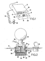
- the system shown in Fig. 1 comprises a housing 2 adapted to be placed e.g. on a table, near the entrance of an establishment such as a dancing hall.
- the housing contains the necessary elec-- tronic circuit elements of the system including an electronic counter of which a display 4 is placed in an inclined front of the housing 2.
- a holder 8 for a marker stamp unit 10 is bult in, said unit 10 being connected to the circuit elements inside the housing 2 by means of a flexible wire 12.
- the inclined front of the housing is provided with a master key operated switch 14 by means of which the counter may be read out through the display 4 or the key switch 14 may be turned into a position enabling the counter and the display 4to be reset by means of a reset pushbutton 16.
- a master key operated switch 14 by means of which the counter may be read out through the display 4 or the key switch 14 may be turned into a position enabling the counter and the display 4to be reset by means of a reset pushbutton 16.
- a master key operated switch 14 by means of which the counter may be read out through the display 4 or the key switch 14 may be turned into a position enabling the counter and the display 4to be reset by means of a reset pushbutton 16.
- a master key operated switch 14 At the left hand side of the holder 8 another key operated switch 18 is placed adapted for the use of the entrance controller in charge of controlling the status of the counter via the display 4.
- a key operated lock 20 for the marker stamp unit 10 when said unit is positioned in the holder 8 (Fig. 2).
- the marker stamp unit 10 is shown in more detail in Fig. 2 where the stamp unit 10 furthermore is locked up in the holder 8 by means of a locking bolt 22 of a key operated lock 20 cooperating with a side recess 24 of the stamp unit 10 through a side opening 26 of a cup-shaped portion 28 of the holder 8.
- a soft marker pad 30 is positioned, said pad being moistened by marker fluid, e.g. of the type used for marking stamp mark which is only visually controllable under ultra-violet lighting.
- the stamp unit 10 is provided with a rubber stamp surface 32, the center area of which being exposed to a downwardly directed press by means of a spring loaded actuator pin 34, the upper opposite end of which cooperates with a signal generator in the form of a microswitch 36 which during normal operation communicates with the counter circuit of the recorder of the admission control system.
- each admission order giving operation thereof effects the micro switch 36 by the pressure on the stamp surface 32 and the actuator pin 34 to generate a signal to the recorder or counter of the system.
- each admission order giving operation effects the micro switch 36 by the pressure on the stamp surface 32 and the actuator pin 34 to generate a signal to the recorder or counter of the system.
- the stamp surface 32 is exposed to the pressure of the giving of an admission order in the form of a stamp mark, e.g. on the back of a hand, this is registered as an admission order giving operation in the recorder unit.
- the stamp surface 32 of the stamp unit 10 has to be remoistened with marker fluid from the marker pad 30 in the bottom of the cup-shaped portion 28 of the holder 8 and as this recharging operation is almost similar to the admission order giving operation ofthe stamp unit 10, the holder 8 or the cup-shaped portion 28 is provided with a sensor coil 38 communicating with a metal ring member 40 positioned around the lower end of the stamp unit 10 so as to enable the recharging operation to be effected without being recorded as an admission order giving operation of the stamp unit 10.
- the ring member 40 of the stamp unit 10 and the sensor coil 38 of the holder 8 belong to a blocking circuit for blocking up the recorder unit from receiving any counting signal from the stamp unit 10 when this is inserted into the holder 8.
- the active sensor portion i.e. the coil 38
- the ring member 40 may also be a part of the stamp unit while in this case the ring member 40 should be positioned in connection with the holder 8.
- Other suitable sensor means may be used for sensing the recharging operation of the stamp unit 10 as being not an admission order giving operation thereof.
- the key operated lock 20 is adapted to lock up the stamp unit 10 in the holder 8 if the entrance controller using the stamp unit 10 has an errand and therefore wants to block up the countingof the admission order giving as he alone carries the responsibility for the contents of the entrance cash box corresponding to the figures of the counter.
- said unit comprises aninternal energy source in the form of a rechargeable electric battery which is automatically switched on in case the external electric power supply should be interrupted.
- the wire connection between the stamp unit 10 and the recorder unit forms part of a security circuit for the said blocking up circuit of the counter. Therefore, if the wire connection between the stamp unit 10 and the recorder unit inside the housing 2 is interrupted, e.g. by removal of the stamp unit by force, the blocking up circuit will immediately be acti- vatedto block the receiving of further signals of the counter.
- the display 4 of the counter is controlled in such a manner that it shows a row of pure zeros after resetting the counter by activating the master key operated key switch 14 and the reset pushbutton 16.
- the entrance controller then activates the stamp unit 10 by the very first admission order giving operation, the display 4 is switched off and the entrance controller operating the stamp unit can only once call for the contents of the counter via the display by means of his own key switch 18. Otherwise the master key operated key switch 14 any time may be used to call forthe actual contents of the counter via the display 4.
- the main unit of the housing 2 is connected to one or more remote control units with a display similar to the display 4 and with a master key operated key switch also.
- the remote control units operates of course parallel to the main unit and they may be positioned in any suitable place in the establishment, e.g. in the office, the bar or the buffet.
Landscapes
- Physics & Mathematics (AREA)
- General Physics & Mathematics (AREA)
- Time Recorders, Dirve Recorders, Access Control (AREA)
- Selective Calling Equipment (AREA)
Claims (4)
Priority Applications (1)
| Application Number | Priority Date | Filing Date | Title |
|---|---|---|---|
| AT83900909T ATE24618T1 (de) | 1982-03-08 | 1983-03-08 | Ueberwachungsverfahren fuer die eintrittskontrolle zu tanzhallen usw. und dessen ausfuehrung. |
Applications Claiming Priority (2)
| Application Number | Priority Date | Filing Date | Title |
|---|---|---|---|
| DK99082A DK99082A (da) | 1982-03-08 | 1982-03-08 | Fremgangsmaade og apparat til adgangskontrol af personer |
| DK990/82 | 1982-03-08 |
Publications (2)
| Publication Number | Publication Date |
|---|---|
| EP0102376A1 EP0102376A1 (de) | 1984-03-14 |
| EP0102376B1 true EP0102376B1 (de) | 1986-12-30 |
Family
ID=8099779
Family Applications (1)
| Application Number | Title | Priority Date | Filing Date |
|---|---|---|---|
| EP83900909A Expired EP0102376B1 (de) | 1982-03-08 | 1983-03-08 | Überwachungsverfahren für die eintrittskontrolle zu tanzhallen usw. und dessen ausführung |
Country Status (5)
| Country | Link |
|---|---|
| EP (1) | EP0102376B1 (de) |
| DE (1) | DE3368784D1 (de) |
| DK (1) | DK99082A (de) |
| NO (1) | NO834036L (de) |
| WO (1) | WO1983003151A1 (de) |
Family Cites Families (2)
| Publication number | Priority date | Publication date | Assignee | Title |
|---|---|---|---|---|
| US1405434A (en) * | 1920-09-10 | 1922-02-07 | Gust C Peterson | Railway-ticket-receipt punch |
| GB598937A (en) * | 1945-09-20 | 1948-03-01 | T I M Ticket Issue Machines Lt | Improvements in or relating to counting mechanism for ticket printing and issuing machines |
-
1982
- 1982-03-08 DK DK99082A patent/DK99082A/da not_active Application Discontinuation
-
1983
- 1983-03-08 EP EP83900909A patent/EP0102376B1/de not_active Expired
- 1983-03-08 DE DE8383900909T patent/DE3368784D1/de not_active Expired
- 1983-03-08 WO PCT/DK1983/000027 patent/WO1983003151A1/en not_active Ceased
- 1983-11-04 NO NO834036A patent/NO834036L/no unknown
Also Published As
| Publication number | Publication date |
|---|---|
| EP0102376A1 (de) | 1984-03-14 |
| DK99082A (da) | 1983-09-09 |
| NO834036L (no) | 1983-11-04 |
| DE3368784D1 (en) | 1987-02-05 |
| WO1983003151A1 (en) | 1983-09-15 |
Similar Documents
| Publication | Publication Date | Title |
|---|---|---|
| US4833307A (en) | Self service dispensing assembly for lottery tickets | |
| US4323770A (en) | Unit particularly for taking stakes and possibly determining the winners in a game such as a national lotto game | |
| US5321241A (en) | System and method for tracking casino promotional funds and apparatus for use therewith | |
| US3124674A (en) | Edwards | |
| AU2002250240B2 (en) | Method and apparatus for controlling access to areas of gaming machines | |
| US7351145B1 (en) | Method and apparatus for accumulating betting data in games of chance | |
| US2967916A (en) | Combination pass card and monitor switch system | |
| WO1997005935A1 (en) | Table game control system | |
| CA2490855A1 (en) | Secure medicament dispensing cabinet, method and system | |
| CA2308097A1 (en) | Control system for trash compaction apparatus including operator identification and authorization features | |
| EP0250226A3 (de) | Spielautomat | |
| JPS6467698A (en) | Card selling apparatus | |
| EP0977618B1 (de) | Schnurloses interaktives spielsystem | |
| EP0102376B1 (de) | Überwachungsverfahren für die eintrittskontrolle zu tanzhallen usw. und dessen ausführung | |
| JPH1033807A (ja) | 遊技機の管理装置 | |
| WO2004018806A1 (ja) | 施錠システム、遊技機及び装置管理システム | |
| EP0511204B1 (de) | Verarbeitungssystem für informationsträger | |
| WO2003082420A1 (fr) | Jeton de jeu, boite de stockage de jetons, table de jeu et systeme de controle de jetons | |
| US5738591A (en) | Queuing system | |
| US2278357A (en) | Identification apparatus | |
| US6089979A (en) | Game-credit control and accounting apparatus | |
| JP3759246B2 (ja) | 遊技機の管理装置 | |
| JPH06312061A (ja) | ゲーム機管理システム | |
| DE3839910C2 (de) | Kontrolleinrichtung für Tischspielgeräte | |
| DE8327248U1 (de) | Einrichtung zur ueberwachung der einlasskontrolle fuer tanzsaele oder dergleichen |
Legal Events
| Date | Code | Title | Description |
|---|---|---|---|
| PUAI | Public reference made under article 153(3) epc to a published international application that has entered the european phase |
Free format text: ORIGINAL CODE: 0009012 |
|
| AK | Designated contracting states |
Designated state(s): AT BE CH DE FR GB LI LU NL SE |
|
| 17P | Request for examination filed |
Effective date: 19840227 |
|
| GRAA | (expected) grant |
Free format text: ORIGINAL CODE: 0009210 |
|
| AK | Designated contracting states |
Kind code of ref document: B1 Designated state(s): AT BE CH DE FR GB LI LU NL SE |
|
| PG25 | Lapsed in a contracting state [announced via postgrant information from national office to epo] |
Ref country code: NL Effective date: 19861230 Ref country code: LI Effective date: 19861230 Ref country code: FR Free format text: THE PATENT HAS BEEN ANNULLED BY A DECISION OF A NATIONAL AUTHORITY Effective date: 19861230 Ref country code: CH Effective date: 19861230 Ref country code: BE Effective date: 19861230 Ref country code: AT Effective date: 19861230 |
|
| REF | Corresponds to: |
Ref document number: 24618 Country of ref document: AT Date of ref document: 19870115 Kind code of ref document: T |
|
| PG25 | Lapsed in a contracting state [announced via postgrant information from national office to epo] |
Ref country code: SE Effective date: 19861231 |
|
| REF | Corresponds to: |
Ref document number: 3368784 Country of ref document: DE Date of ref document: 19870205 |
|
| PG25 | Lapsed in a contracting state [announced via postgrant information from national office to epo] |
Ref country code: LU Free format text: LAPSE BECAUSE OF NON-PAYMENT OF DUE FEES Effective date: 19870331 |
|
| REG | Reference to a national code |
Ref country code: CH Ref legal event code: PL |
|
| EN | Fr: translation not filed | ||
| NLV1 | Nl: lapsed or annulled due to failure to fulfill the requirements of art. 29p and 29m of the patents act | ||
| PLBE | No opposition filed within time limit |
Free format text: ORIGINAL CODE: 0009261 |
|
| STAA | Information on the status of an ep patent application or granted ep patent |
Free format text: STATUS: NO OPPOSITION FILED WITHIN TIME LIMIT |
|
| PG25 | Lapsed in a contracting state [announced via postgrant information from national office to epo] |
Ref country code: DE Effective date: 19871201 |
|
| 26N | No opposition filed | ||
| PG25 | Lapsed in a contracting state [announced via postgrant information from national office to epo] |
Ref country code: GB Free format text: LAPSE BECAUSE OF NON-PAYMENT OF DUE FEES Effective date: 19881122 |