EP0102384B1 - Reseau double bidirectionnel - Google Patents
Reseau double bidirectionnel Download PDFInfo
- Publication number
- EP0102384B1 EP0102384B1 EP19830901137 EP83901137A EP0102384B1 EP 0102384 B1 EP0102384 B1 EP 0102384B1 EP 19830901137 EP19830901137 EP 19830901137 EP 83901137 A EP83901137 A EP 83901137A EP 0102384 B1 EP0102384 B1 EP 0102384B1
- Authority
- EP
- European Patent Office
- Prior art keywords
- network
- signals
- station units
- networks
- units
- Prior art date
- Legal status (The legal status is an assumption and is not a legal conclusion. Google has not performed a legal analysis and makes no representation as to the accuracy of the status listed.)
- Expired
Links
Images

Classifications
-
- H—ELECTRICITY
- H04—ELECTRIC COMMUNICATION TECHNIQUE
- H04L—TRANSMISSION OF DIGITAL INFORMATION, e.g. TELEGRAPHIC COMMUNICATION
- H04L12/00—Data switching networks
- H04L12/28—Data switching networks characterised by path configuration, e.g. LAN [Local Area Networks] or WAN [Wide Area Networks]
- H04L12/40—Bus networks
- H04L12/407—Bus networks with decentralised control
- H04L12/413—Bus networks with decentralised control with random access, e.g. carrier-sense multiple-access with collision detection [CSMA-CD]
- H04L12/4135—Bus networks with decentralised control with random access, e.g. carrier-sense multiple-access with collision detection [CSMA-CD] using bit-wise arbitration
-
- H—ELECTRICITY
- H04—ELECTRIC COMMUNICATION TECHNIQUE
- H04L—TRANSMISSION OF DIGITAL INFORMATION, e.g. TELEGRAPHIC COMMUNICATION
- H04L12/00—Data switching networks
- H04L12/28—Data switching networks characterised by path configuration, e.g. LAN [Local Area Networks] or WAN [Wide Area Networks]
- H04L12/40—Bus networks
- H04L12/403—Bus networks with centralised control, e.g. polling
Definitions
- This invention relates to digital bus communication networks.
- a communication system having a first network including at least two station units characterised by a second network, including at least two station units; allocation means for allocating the resources of the first and second networks; a communication pathway over which the station units are capable of communicating with each other and with the allocation means; and the first and second networks being capable of simultaneous operation, the simultaneous operation being so arranged that at any point along the pathway common to the station units, signals between the station units of the first network propagate in a direction opposite to that of the signals between the station units of the second network, the latter signals being unrelated to the former signals.
- the embodiment of the present invention is directed to means for increasing both the size and data handling capacity of multiple-access communication systems.
- two, operationally independent networks are established along a common transmission bus by transmitting signals in opposite directions.
- Each network comprises a plurality of station interface units which are directionally coupled to the transmission bus so that they transmit and receive signals in one or the other of the two signal directions.
- the two networks can operate at different bit rates and at different wavelengths. It is a further advantage that they can be organized at different times as the need arises.
- Fig. 1 shows a prior art multiple-access communication network comprising an open loop transmission bus 10 which is divided into two branches 11 and 12.
- Branch 11 is the so-called “talk” branch in which signals flow from right to left.
- Branch 12 is the so-called “listen” branch in which signals flow from left to right.
- Station equipment though not shown, can include a variety of services including computers, telephones, video equipment, etc.
- the output end of the talk branch and the input end of the listen branch are connected to a central control unit (CCU).
- CCU central control unit
- the opposite (i.e., open) ends of the two branches are match-terminated by impedances 20 and 21 so as to minimize reflections in the network.
- the central control unit can be located anywhere along the transmission bus 10.
- a regenerator 9 is advantageously located at the junction of the two branches, it is convenient to locate the regenerator and CCU together, as shown in Fig. 1.
- the purpose of the central control unit is to allocate among the station interface units, at their request, the resources of the network. Precisely what this entails will vary from system to system. In general, it will include maintaining up-to-date tables of the state of the network and of the network configuration. Subject to availability, as indicated by these tables, channels will be assigned to the station interface units upon request.
- the CCU will perform no switching. As a consequence it can be simple in construction. Furthermore, once a circuit is established between subscriber stations, the CCU is no longer involved, and because it does not operate on the subscriber's data, it imposes no constraints on data rate, data format, type of modulation or type of multiplexing.
- a network of this general type has a finite capacity which is limited by the SIUs. If the network needs, after a time, exceed this capacity, these units must either be reprogrammed, if they are computers, or replaced.
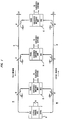
- the present invention provides an alternative approach wherein a second network is superimposed upon the existing network without any disruption in the original network. The manner in which this is done is illustrated in Fig. 2. In this figure, the same identification numerals are used to identify corresponding components in Fig. 1. In addition, the description of the components include the suffix (A) or (B).
- the network of Fig. 2 comprises, as in Fig. 1, a transmission bus 10 having a talk branch 11 and a listen branch 12.
- a first plurality of station interface units (SIU[A]) 13, 14 and 15 are directionally coupled to the two branches by means of directional couplers 16-16', 17-17' and 18-18', respectively.
- the connections are made so that transmissions from each SIU(A) transmitter propagates along the talk branch 11 from right to left, as indicated by the (A) identified arrows.
- each SIU(A) is directionally coupled to the listen branch 12 so that only those signals propagating from left to right, as also indicated by the (A) identified arrows, are received by the SIU(A) receivers.
- central control unit (19) and data regenerator 9, associated with the (A) network are connected between the talk and listen branches.
- each directional coupler In the single network configuration, the fourth port of each directional coupler is match-terminated. In the dual network of Fig. 2 these terminations are removed at specified station interface locations, and another station interface unit is connected in their stead. Thus, station interface units 23 and 24 are connected, respectively, to the fourth port of directional couplers 16 and 16', and 17 and 17'. For purposes of illustration, a unit has not been connected between couplers 18 and 18'.
- units identified as SIU(B) transmit signals onto the talk branch so as to propagate from left-to-right, and receive signals that propagate along the listen branch from right- to-left. In both cases, as indicated by the (B) identified arrows, this is opposite to the direction of propagation of the corresponding (A) network signals.
- a second central control unit (CCU[B]) 29 and associated regenerator 30 are connected at the right hand end of the transmission bus 10, thereby closing one end of the B network loop.
- signals originating at any station associated with an (A) network SIU are transmitted to CCU(A) and data regenerator 9 where they are received, acted upon, regenerated, and retransmitted to the receiving ends of the (A) network SlUs.
- signals originating in CCU(A) or regenerated by regenerator 9 are transmitted and received solely by (A) network SlUs.
- signals associated with the (B) network are electrically isolated from the (A) network units so that in every sense the two networks are operationally independent in spite of the fact that they share a common transmission bus 10.
- the two networks can have totally different signal protocols and data rates, and each can be added to as the need arises.
- each branch 11 and 12 is match-terminated so as to minimize signal reflections in the respective branches.
- Fig. 2 there appears to be no terminating impedances as each end of the loop is terminated by a CCU and regenerator.
- the input and output impedances of these units are advantageously designed to provide the desired terminations.
- (A) network signals in branch 12 are terminated at the output port of CCU(B) 29 as are (B) network signals at the output port of CCU(A) 19.
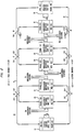
- Fig. 3 shows an alternate embodiment of the invention incorporating two modifications, each of which can be used independently of the other.
- a common transmission bus 30 with station interface units 50, 51, 52 and 53 directionally coupled between the talk and listen branches 31 and 32 of bus 30.
- a second transmission bus 34 which is used to transmit timing signals to the various units, as would be the case in a synchronous system.
- the timing signals are derived from a pair of clock sources 42 and 44. Each source is coupled to a transmission bus 34 by means of a wavelength multiplexer 43 and 45, respectively, which injects the timing signals in the appropriate direction.
- multiplexer 43 derives (B) network timing signals t B from source 42 and causes them to propagate in the same direction as the (B) network data signals propagate along transmission bus 30.
- multiplexer 45 derives network timing signals t A from source 44 and causes them to propagate along bus 34 in the opposite direction. Both diplexers are transparent to transmissions at the wavelength of the other clock source.
- the second modification relates to the use of a common CCU for both the (A) and (B) networks.
- a single CCU (A, B) 40 is provided.
- the CCU is located at the end of the loop which also includes the (A) network clock regenerator 39 and data regenerator 38.
- the (B) network data regenerator 41 and clock regenerator 46 are located at the other end of the loop.
- both networks are to be controlled by the same CCU, there must be communication between the two networks. This is provided at the station interface units by connections 64 and 47. These connections are only employed for the purpose of establishing a link between subscribers. Once the link is made, however, communication between subscribers is via their respective station interface units and, in all other respects, the networks are operationally independent.
Landscapes
- Engineering & Computer Science (AREA)
- Computer Networks & Wireless Communication (AREA)
- Signal Processing (AREA)
- Small-Scale Networks (AREA)
- Use Of Switch Circuits For Exchanges And Methods Of Control Of Multiplex Exchanges (AREA)
- Data Exchanges In Wide-Area Networks (AREA)
Claims (8)
Applications Claiming Priority (2)
| Application Number | Priority Date | Filing Date | Title |
|---|---|---|---|
| US35777282A | 1982-03-12 | 1982-03-12 | |
| US357772 | 1982-03-12 |
Publications (3)
| Publication Number | Publication Date |
|---|---|
| EP0102384A1 EP0102384A1 (fr) | 1984-03-14 |
| EP0102384A4 EP0102384A4 (fr) | 1984-08-10 |
| EP0102384B1 true EP0102384B1 (fr) | 1988-01-07 |
Family
ID=23406969
Family Applications (1)
| Application Number | Title | Priority Date | Filing Date |
|---|---|---|---|
| EP19830901137 Expired EP0102384B1 (fr) | 1982-03-12 | 1983-02-24 | Reseau double bidirectionnel |
Country Status (5)
| Country | Link |
|---|---|
| EP (1) | EP0102384B1 (fr) |
| JP (1) | JPH0638604B2 (fr) |
| CA (1) | CA1194959A (fr) |
| DE (1) | DE3375268D1 (fr) |
| WO (1) | WO1983003327A1 (fr) |
Families Citing this family (5)
| Publication number | Priority date | Publication date | Assignee | Title |
|---|---|---|---|---|
| FR2554294B1 (fr) * | 1983-10-28 | 1990-03-16 | Dassault Electronique | Dispositif pour l'echange d'informations numeriques entre plusieurs postes |
| US4983008A (en) * | 1986-08-22 | 1991-01-08 | Raychem Corporation | Strained distributed optical fiber communication system |
| ES2040753T3 (es) * | 1986-08-22 | 1993-11-01 | Raychem Corporation (A California Corporation) | Sistema de comunicacion de fibra optica distribuida en forma tensada. |
| DE10349465B4 (de) * | 2003-10-23 | 2014-04-03 | Südzucker Aktiengesellschaft Mannheim/Ochsenfurt | Gelatinefreie, Isomaltulose-haltige Weichkaramelle |
| RU2372726C2 (ru) * | 2007-07-17 | 2009-11-10 | Александр Геннадьевич Попов | Двойная пассивная волоконно-оптическая сеть |
Family Cites Families (4)
| Publication number | Priority date | Publication date | Assignee | Title |
|---|---|---|---|---|
| US4090067A (en) * | 1976-11-02 | 1978-05-16 | Sperry Rand Corporation | Optical data communication system |
| US4186380A (en) * | 1977-10-21 | 1980-01-29 | Minnesota Mining And Manufacturing Company | Multi-terminal computer system with dual communication channels |
| US4210780A (en) * | 1978-03-27 | 1980-07-01 | The Mitre Corporation | Multiple access digital communications system |
| US4317614A (en) * | 1980-02-20 | 1982-03-02 | General Dynamics, Pomona Division | Fiber optic bus manifold |
-
1983
- 1983-02-24 JP JP50120183A patent/JPH0638604B2/ja not_active Expired - Lifetime
- 1983-02-24 DE DE8383901137T patent/DE3375268D1/de not_active Expired
- 1983-02-24 WO PCT/US1983/000243 patent/WO1983003327A1/fr not_active Ceased
- 1983-02-24 EP EP19830901137 patent/EP0102384B1/fr not_active Expired
- 1983-02-28 CA CA000422518A patent/CA1194959A/fr not_active Expired
Also Published As
| Publication number | Publication date |
|---|---|
| DE3375268D1 (en) | 1988-02-11 |
| EP0102384A4 (fr) | 1984-08-10 |
| CA1194959A (fr) | 1985-10-08 |
| WO1983003327A1 (fr) | 1983-09-29 |
| EP0102384A1 (fr) | 1984-03-14 |
| JPS59500396A (ja) | 1984-03-08 |
| JPH0638604B2 (ja) | 1994-05-18 |
Similar Documents
| Publication | Publication Date | Title |
|---|---|---|
| US4630256A (en) | Bidirectional dual network | |
| US5161153A (en) | Synchronous network | |
| CA1280465C (fr) | Fond de panier optique | |
| EP0079150B1 (fr) | Système de communications de données avec largeur de bande effective élevée | |
| SE456789B (sv) | Kommunikationsanlaeggning av dubbelbusstyp | |
| US4347605A (en) | Multiplexed telecommunication systems | |
| US4789980A (en) | Switching techniques for FDM communication systems | |
| JPS6041341A (ja) | 時分割双方向伝送方式 | |
| EP0102384B1 (fr) | Reseau double bidirectionnel | |
| US4957340A (en) | Synchronous multifrequency optical network | |
| KR940017431A (ko) | 다수의 데이타 채널을 갖는 로킬 통신 시스템 및 그 시스템에 사용하기 위한 장치 | |
| JPH04278739A (ja) | モジュール式能動光ファイバカップラユニット及びそのシステム | |
| JPS58206257A (ja) | ル−プ多重伝送方式 | |
| US4955013A (en) | Operating a multiple-access optical network | |
| EP0435467A2 (fr) | Réseau optique | |
| EP1063595B1 (fr) | Module d'interface de réseau et de signaux vidéo | |
| JPS58172039A (ja) | 光伝送システム | |
| KR100301856B1 (ko) | 광커플러를이용한광통신시스템 | |
| EP0423942B1 (fr) | Réseau synchrone | |
| JPH01174193A (ja) | 統合デジタル通信サービス網における多重装置 | |
| JPS63152235A (ja) | 光ロ−カルエリアネツトワ−ク | |
| JPS63177628A (ja) | 光スタ−ネツトワ−クシステム | |
| JPH0624385B2 (ja) | 信号伝送方式 | |
| JPS6157148A (ja) | 信号伝送方式 | |
| JPH0356025B2 (fr) |
Legal Events
| Date | Code | Title | Description |
|---|---|---|---|
| PUAI | Public reference made under article 153(3) epc to a published international application that has entered the european phase |
Free format text: ORIGINAL CODE: 0009012 |
|
| AK | Designated contracting states |
Designated state(s): DE FR GB NL SE |
|
| 17P | Request for examination filed |
Effective date: 19840302 |
|
| GRAA | (expected) grant |
Free format text: ORIGINAL CODE: 0009210 |
|
| AK | Designated contracting states |
Kind code of ref document: B1 Designated state(s): DE FR GB NL SE |
|
| REF | Corresponds to: |
Ref document number: 3375268 Country of ref document: DE Date of ref document: 19880211 |
|
| ET | Fr: translation filed | ||
| PLBE | No opposition filed within time limit |
Free format text: ORIGINAL CODE: 0009261 |
|
| STAA | Information on the status of an ep patent application or granted ep patent |
Free format text: STATUS: NO OPPOSITION FILED WITHIN TIME LIMIT |
|
| 26N | No opposition filed | ||
| EAL | Se: european patent in force in sweden |
Ref document number: 83901137.6 |
|
| PGFP | Annual fee paid to national office [announced via postgrant information from national office to epo] |
Ref country code: SE Payment date: 19991223 Year of fee payment: 18 |
|
| PGFP | Annual fee paid to national office [announced via postgrant information from national office to epo] |
Ref country code: FR Payment date: 20000124 Year of fee payment: 18 |
|
| PGFP | Annual fee paid to national office [announced via postgrant information from national office to epo] |
Ref country code: NL Payment date: 20000125 Year of fee payment: 18 |
|
| PGFP | Annual fee paid to national office [announced via postgrant information from national office to epo] |
Ref country code: GB Payment date: 20000209 Year of fee payment: 18 |
|
| PGFP | Annual fee paid to national office [announced via postgrant information from national office to epo] |
Ref country code: DE Payment date: 20000331 Year of fee payment: 18 |
|
| PG25 | Lapsed in a contracting state [announced via postgrant information from national office to epo] |
Ref country code: GB Free format text: LAPSE BECAUSE OF NON-PAYMENT OF DUE FEES Effective date: 20010224 |
|
| PG25 | Lapsed in a contracting state [announced via postgrant information from national office to epo] |
Ref country code: SE Free format text: LAPSE BECAUSE OF NON-PAYMENT OF DUE FEES Effective date: 20010225 |
|
| PG25 | Lapsed in a contracting state [announced via postgrant information from national office to epo] |
Ref country code: NL Free format text: LAPSE BECAUSE OF NON-PAYMENT OF DUE FEES Effective date: 20010901 |
|
| EUG | Se: european patent has lapsed |
Ref document number: 83901137.6 |
|
| GBPC | Gb: european patent ceased through non-payment of renewal fee |
Effective date: 20010224 |
|
| PG25 | Lapsed in a contracting state [announced via postgrant information from national office to epo] |
Ref country code: FR Free format text: LAPSE BECAUSE OF NON-PAYMENT OF DUE FEES Effective date: 20011031 |
|
| NLV4 | Nl: lapsed or anulled due to non-payment of the annual fee |
Effective date: 20010901 |
|
| REG | Reference to a national code |
Ref country code: FR Ref legal event code: ST |
|
| PG25 | Lapsed in a contracting state [announced via postgrant information from national office to epo] |
Ref country code: DE Free format text: LAPSE BECAUSE OF NON-PAYMENT OF DUE FEES Effective date: 20011201 |