EP0102392A1 - Procede et dispositif de fabrication de materiau de formage en feuille - Google Patents
Procede et dispositif de fabrication de materiau de formage en feuille Download PDFInfo
- Publication number
- EP0102392A1 EP0102392A1 EP82901618A EP82901618A EP0102392A1 EP 0102392 A1 EP0102392 A1 EP 0102392A1 EP 82901618 A EP82901618 A EP 82901618A EP 82901618 A EP82901618 A EP 82901618A EP 0102392 A1 EP0102392 A1 EP 0102392A1
- Authority
- EP
- European Patent Office
- Prior art keywords
- winding
- linear material
- weft
- cylindrically formed
- flat belt
- Prior art date
- Legal status (The legal status is an assumption and is not a legal conclusion. Google has not performed a legal analysis and makes no representation as to the accuracy of the status listed.)
- Withdrawn
Links
Images


Classifications
-
- D—TEXTILES; PAPER
- D04—BRAIDING; LACE-MAKING; KNITTING; TRIMMINGS; NON-WOVEN FABRICS
- D04H—MAKING TEXTILE FABRICS, e.g. FROM FIBRES OR FILAMENTARY MATERIAL; FABRICS MADE BY SUCH PROCESSES OR APPARATUS, e.g. FELTS, NON-WOVEN FABRICS; COTTON-WOOL; WADDING ; NON-WOVEN FABRICS FROM STAPLE FIBRES, FILAMENTS OR YARNS, BONDED WITH AT LEAST ONE WEB-LIKE MATERIAL DURING THEIR CONSOLIDATION
- D04H3/00—Non-woven fabrics formed wholly or mainly of yarns or like filamentary material of substantial length
- D04H3/02—Non-woven fabrics formed wholly or mainly of yarns or like filamentary material of substantial length characterised by the method of forming fleeces or layers, e.g. reorientation of yarns or filaments
- D04H3/04—Non-woven fabrics formed wholly or mainly of yarns or like filamentary material of substantial length characterised by the method of forming fleeces or layers, e.g. reorientation of yarns or filaments in rectilinear paths, e.g. crossing at right angles
-
- B—PERFORMING OPERATIONS; TRANSPORTING
- B26—HAND CUTTING TOOLS; CUTTING; SEVERING
- B26D—CUTTING; DETAILS COMMON TO MACHINES FOR PERFORATING, PUNCHING, CUTTING-OUT, STAMPING-OUT OR SEVERING
- B26D3/00—Cutting work characterised by the nature of the cut made; Apparatus therefor
- B26D3/001—Cutting tubes longitudinally
-
- B—PERFORMING OPERATIONS; TRANSPORTING
- B26—HAND CUTTING TOOLS; CUTTING; SEVERING
- B26D—CUTTING; DETAILS COMMON TO MACHINES FOR PERFORATING, PUNCHING, CUTTING-OUT, STAMPING-OUT OR SEVERING
- B26D3/00—Cutting work characterised by the nature of the cut made; Apparatus therefor
- B26D3/16—Cutting rods or tubes transversely
- B26D3/162—Cutting rods or tubes transversely cutting tubes obliquely
-
- B—PERFORMING OPERATIONS; TRANSPORTING
- B29—WORKING OF PLASTICS; WORKING OF SUBSTANCES IN A PLASTIC STATE IN GENERAL
- B29C—SHAPING OR JOINING OF PLASTICS; SHAPING OF MATERIAL IN A PLASTIC STATE, NOT OTHERWISE PROVIDED FOR; AFTER-TREATMENT OF THE SHAPED PRODUCTS, e.g. REPAIRING
- B29C53/00—Shaping by bending, folding, twisting, straightening or flattening; Apparatus therefor
- B29C53/56—Winding and joining, e.g. winding spirally
- B29C53/58—Winding and joining, e.g. winding spirally helically
- B29C53/74—Winding and joining, e.g. winding spirally helically using a forming surface inthe shape of an endless belt which is recycled after the forming operation
-
- B—PERFORMING OPERATIONS; TRANSPORTING
- B29—WORKING OF PLASTICS; WORKING OF SUBSTANCES IN A PLASTIC STATE IN GENERAL
- B29C—SHAPING OR JOINING OF PLASTICS; SHAPING OF MATERIAL IN A PLASTIC STATE, NOT OTHERWISE PROVIDED FOR; AFTER-TREATMENT OF THE SHAPED PRODUCTS, e.g. REPAIRING
- B29C53/00—Shaping by bending, folding, twisting, straightening or flattening; Apparatus therefor
- B29C53/80—Component parts, details or accessories; Auxiliary operations
- B29C53/8008—Component parts, details or accessories; Auxiliary operations specially adapted for winding and joining
- B29C53/8016—Storing, feeding or applying winding materials, e.g. reels, thread guides, tensioners
-
- Y—GENERAL TAGGING OF NEW TECHNOLOGICAL DEVELOPMENTS; GENERAL TAGGING OF CROSS-SECTIONAL TECHNOLOGIES SPANNING OVER SEVERAL SECTIONS OF THE IPC; TECHNICAL SUBJECTS COVERED BY FORMER USPC CROSS-REFERENCE ART COLLECTIONS [XRACs] AND DIGESTS
- Y10—TECHNICAL SUBJECTS COVERED BY FORMER USPC
- Y10S—TECHNICAL SUBJECTS COVERED BY FORMER USPC CROSS-REFERENCE ART COLLECTIONS [XRACs] AND DIGESTS
- Y10S118/00—Coating apparatus
- Y10S118/11—Pipe and tube outside
Definitions
- the present invention relates-to a method and an apparatus for producing a sheet molding compound.
- linear material as used herein and in the appended claims is to be understood to mean any such materials as vegetable fiber, animal fiber, mineral fiber, synthetic fiber, metal wire, and the like.
- Glass fiber sheet used heretofore was a textile fabric in which warps and wefts were crossed and interwoven together as in a common textile fabric. In such woven glass fiber sheet, however, there was a tendency that the threads bent at intersections were easy to break, resulting in a disadvantage to decrease the strength of the sheet as a whole.
- a sheet used as a reinforcing material of a product of a reinforced synthetic resin is preferably not a woven sheet but an unwoven sheet in which warps and wefts are laid on each other in a lattice shape. In producing a long belt-like sheet in this way, however, arrangement of wefts was difficult and inefficient. Accordingly, continuous production of such sheet was impossible, and multi-layer arrangement of warps and wefts was difficult.
- an object of the present invention is to provide a method and an apparatus for producing a sheet molding compound without weaving linear materials, which are simple and economical and yet are capable of obviating disadvantages of the conventional winding processes.
- the method according to the present invention comprises the steps of circulating a flat belt, changing the shape of the flat belt in the intermediate portion thereof into a cylindrical form, guiding a carrier film and warp linear materials longitudinally of the cylindrically formed portion, winding a weft linear material thereon, supplying synthetic resin, cutting open the cylindrically formed body comprising the warp linear materials and the weft linear material longitudinally into a belt-like sheet, and winding up the belt-like sheet.
- the method according to the present invention is characterized in that the flat belt is changed in shape at the intermediate portion thereof into the cylindrical form and the weft linear material is wound thereabout.
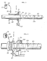
- the apparatus according to the present invention comprises a belt circulator 1, a winder 2, a warp linear material feeder 3, a carrier film feeder 4, a synthetic resin feeder 5, a cutter 6, and a compound winder 7.
- the belt circulator 1 comprises a flat belt 11, guide rollers 12, a driving roller 13, an hourglass roller 14, an annular guide 15, and a core bar 16.
- the flat belt 11 is supported by the guide rollers 12 for circulation in a predetermined passage and is driven by the driving roller 13.
- the flat belt 11 is circulated in the most part in a flat belt-like form as shown in Fig. 2, but only in the part corresponding to the guide of the warp linear material and the weft linear material as will be described hereinafter, it is forced by the hourglass roller 14 and the annular guide 15 to be curved widthwise into a cylindrical shape for passage therethrough. That is, the flat belt 11 is preformed by the hourglass roller 14 into the cylindrical shape and then inserted into the central bore of the annular guide 15 to be formed into the cylindrical shape having the diameter substantially identical to the inner diameter of the central bore of the annular guide 15.
- a common conveyor belt or a power transmission belt of such material as leather, textile fabric, rubber, steel or the like may be used as the flat belt 11.
- the annular guide 15 is provided with a plurality of warp guide bores 151 arranged concentrically about the belt guide hole, whereby linear materials 30 (hereinafter called warp linear materials) payed out from a plurality of warp linear material bobbins 31 are inserted into the warp guide bores 151 respectively, so that the warp linear materials arranged as a cylindrical form along the cylindrical portion of the flat belt 11 are advanced in parallel in the direction of an arrow as shown in Fig. 1.
- warp linear materials hereinafter called warp linear materials
- the core bar 16 is inserted through the cylindrically formed portion of the flat belt 11 to prevent the belt from deformation in winding the weft linear material as will be described hereinafter. In the case where the flat belt 11 has a sufficient rigidity to resist the winding force, the core bar is not required.
- weft linear material 20 the step for winding the linear material intended to be the weft (hereinafter called weft linear material) 20 will be described.
- the step for feeding synthetic resin is performed.
- the synthetic resin feeding step will be described hereinafter with reference to Figs. 16 - to 19.
- the cylindrically formed portion lla (hereinafter called the winding core) of the flat belt 11 is inserted coaxially through a winding disk 21 and a winding drum 22, and supported free from contact therewith.
- the winding core lla is movable axially thereof and the winding disk 21 is rotatable about the axis of the winding core lla.
- the winding disk 21 is provided with at least one guide hole 211 on the outer periphery thereof.
- a bobbin 23 having the weft linear material 20 wound therearound is located at a predetermined position.
- a binding position 24 is established at a position downstream of and adjacent to the winding disk 21 with respect to the direction of movement of the winding core lla.
- winding disk 21 and the winding drum 22 may take any of the three different constructions, in which they are formed integrally (Fig. 4A), they are connected rotatably relative to each other (Fig. 4B), and the winding drum 22 is fixed while the winding disk 21 is supported rotatably therewith (Fig. 4C).
- the winding drum 22 is positioned upstream of and adjacent to the winding disk 21 with respect to the direction of movement of the winding core lla.
- a linear material 251 is wound around the outer peripheral surface of the winding core lla using a binder 25 (Fig. 5).
- the linear material 251 used for binding is preferably of the equal quality to the weft linear material 20.
- the weft linear material 20 is pulled out from a bobbin 23, passed through a suitable guide 26, wound around the winding drum 22 suitable times, passed through the guide holes 211 of the winding disk 21, and fixed at the leading end thereof to a suitable position on the outer peripheral surface of the winding core lla. Thereafter, the winding disk 21 is rotated in the predetermined direction while the winding core lla is moved axially in the predetermined direction (for example, to.the right in Fig. 3).
- the linear material 20 is wound on both of the winding drum 22 and the winding core lla. That is, as shown schematically in Fig. 3, the linear material 20 is firstly wound on the winding drum 22, slides thereon, passes through the guide hole 211 of the winding disk 21, and is wound on the'winding core lla.
- the number of turns of the linear material 20 wound on the winding drum 22 is the same as the number of turns of the linear material wound on the winding core lla except the number of turns thereof initially wound on the winding drum 22.
- the winding pitch of the weft linear material 20 wound on the winding core lla can be changed by controlling the speed of movement of the winding core lla or the speed of rotation of the winding disk 21. In this manner, the linear material 20 can be wound on the winding core lla in a rough pitch and on the widning drum 22 in a tight pitch.
- the terminal end of the winding on the winding core lla is bound by another linear material 251 using the binder 25 at the binding position 24 so as to keep the terminal end of the winding from being unwound off the winding core lla.
- the winding disk 21 is rotated in the direction reverse to that in the preceding occasion.
- the linear material while being unwound from the winding on the winding drum 22, is wound on the winding core lla in the direction reverse to that in the preceding occasion.
- the. weft linear material 20 while being wound on the winding drum 22 in the direction reverse to that in the preceding occasion, is continuously wound on the winding core 11a.
- the reverse rotation of the winding disk 21 is performed preferably in synchronism with the binding operation.
- the movement of the winding core lla may be temporarily stopped-during the binding operation or the binding position 24 may be shifted within a predetermined range in time with the speed of movement, of the winding core 11a.
- the winding drum 22 is plated, attached thereon with a low-fricticnal material or provided with idle rollers on the outer surface thereof for smooth sliding of the weft linear material thereon.
- the winding disk 21 By providing the winding disk 21 with a plurality of the guide holes 211, it is made possible to wind a plurality of pieces of the weft linear materials 20 simultaneously on the winding core lla.
- Fig. 5 The construction of Fig. 5 is substantially identical to that of Fig. 3.
- the synthetic resin feeder 5 described in detail hereinbelow is disposed on the entrance side, on the exit side, or both,.of the winder 2.
- the binder 25 is disposed at the binding position 24.
- the winding disk 21 is rotated alternately in normal and reverse directions with a predetermined period and at a predetermined speed by a driving mechanism 27.
- the binder 25 is satisfactory if it has the function to wind the linear material 251 on the outer peripheral surface of the winding core lla once or twice and bind it.
- a commercially available automatic packing machine may be utilized. Since such automatic packing machine is capable of operating at a high speed requiring only 2-5 seconds for one cycle of operation, it causes no particular hindrance to the binding operation during the ordinary winding operation. In order to achieve secure binding, however, it is preferable to stop the winding core lla temporarily only during the binding operation or to move the binder 25 over a predetermined distance in synchronism with the winding core lla.
- the actual length of the weft linear material 20 wound helically in the same direction is dependent upon the diameter and the number of pieces of the weft linear materials supplied, the diameter and the number of rotation of the winding drum, and the diameter and the feed speed of the winding core, but may be determined to the range from 10 to 15m at largest. Accordingly, the product according to the present invention can be used as a common sheet molding compound without hindrance. Further, since the cylindrically formed body of the weft linear material and others is cut open longitudinally by the cutter 6 described in detail hereinbelow at an adequate position, the winding core lla need not be so long as 10-15m.
- the winding disk 21 and the winding drum 22 may be constructed in any of the relationships shown in Figs. 4A to 4C, the concrete construction of which will be described in detail below.
- the embodiment shown in Figs. 6 and 7 corresponds to the construction shown in Fig. 4A. That is, the-winding disk 21 and the winding drum 22 are formed integrally with each other and supported rotatably with respect to a support frame 28 by a slide ring 221.
- the winding core.lla is inserted through the central holes of the winding disk 21 and the winding drum 22 and is supported against contact therewith.
- a disk 271 of the drive mechanism 27 is in frictional contact with the outer peripheral surface of the.winding disk 21.
- the weft linear material 20 passes through any one of a plurality of the guides 26 provided in the support frame 28, turns around the outer peripheral surface of the winding drum 22, passes through the guide hole 211 provided in the winding disk 21, and is fixed in the leading end thereof to an arbitrary position on the winding core lla.
- the embodiment shown in Figs. 8 and 9 corresponds to the construction of Fig. 4B.
- the winding disk 21 and the winding drum 22 are connected relatively rotatably through conventional roller bearings 222.
- a The winding drum 22 is supported rotatably with respect to the support frame 28 through the roller bearings 222.
- the winding disk 21 is serrated on the outer periphery thereof for engagement with idle gears 223 and a driving gear 272 of the drive mechanism 27.
- the winding disk 21 is supported by the idle gears 223 rotatably at a predetermined position and is rotatably driven by the driving gear 272.
- the embodiment shown in Fig. 10 corresponds to the construction of Fig. 4C.
- the winding drum 22 is supported fixedly by the support frame 28.
- the winding disk 21 is connected rotatably with respect to the winding drum 22 through the roller bearings 222.
- a pulley 225 is fixed to the side of the winding disk 21 and is connected to a driving pulley 273 of the driving.mechanism 27 through a belt 274.
- the winding disk 21 is supported rotatably at a predetermined position by a roller 226 and is rotatably driven by the driving pulley 273.
- the system for rotatably driving the winding disk 21 is not specifically limited to the embodiments described above but may be interchanged as required.
- the guide hole 211 may be provided directly at the forward end of the winding drum 22 as shown in Fig. 11, without forming the winding disk 21 specifically.
- FIG. 12 An example of the mechanism for preventing loosening of the winding is shown in Fig. 12.
- the winding disk 21 and the winding drum-22 are connected relatively rotatably, and a pair of coil springs 231 are interposed between them so that a reaction force is transmitted to the winding drum 22 through the springs 231 during the reverse rotation of the winding disk 21.
- rollers 232 rotatably along the outer peripheral surface of the winding drum 22 as shown in Fig. 13.
- a linear material guide mechanism is shown in Fig. 14.
- the rotating elements can be formed light in weight and small in size, thereby making it possible to wind a number of weft linear materials simultaneously around the winding core lla.
- the bobbins 23 having the weft linear materials 20 wound therearound are arranged together at one place and the weft linear materials 20 payed out from the bobbins 23 are directed through respective guide pipes 261 to the respective guides 26 provided in the support frame 28.
- the similar construction may be applied to guide the warp linear materials.
- the warp linear material feeder 3 will now be described with reference to Figs. 1 and 15.
- a plurality of the warp linear material bobbins 31 are disposed on the upstream side .-of and surrounding the flat belt 11.
- the warp linear materials 30 payed out from the warp linear material bobbins 31 are passed through the warp guide bores 151 of the annular guide 15, respectively, and are guided around and longitudinally of the cylindrically formed winding core lla. Thereafter, the weft linear materials 20 are wound around the warp linear materials 30 as described hereinabove.
- the carrier film feeder 4 comprises a carrier film roll 41 disposed on the upstream side of and above the flat belt 11.
- a carrier film 40 payed out from the roll 41 is formed into a cylindrical shape together with the flat belt 11 by the hourglass roller 14 and passes through the annular guide 15.
- the warp linear materials 30 and the weft linear materials 20 are arranged around the outer peripheral surface of the cylindrically formed portion of the carrier film 40 and the flat belt 11.
- the carrier film 40 functions to separate the warp linear materials 30 and the weft linear materials 20 from the flat belt 11 and also to keep the layers of the windings from contact with each other when wound in roll by the compound winder 7 as will be described hereinbelow.
- the carrier film 40 must be separated from the compound.
- the synthetic resin feeder 5 is disposed on the entrance side or on the exit side or on both sides of the winder 2 and has the construction to surround the outer peripheral surface of the cylindrically formed body of the warp linear materials 30 or of the warp linear materials 30 and the weft linear materials 20.
- the synthetic resin feeder 5 may take any of the construction, as shown in Fig. 16, in which a nozzle 51 is in direct contact with the outer peripheral surface of the cylindrically formed body to supply a synthetic resin 50 thereto or the construction, as shown in Fig. 17, in which the nozzle 51 is slightly spaced from the outer peripheral surface of the cylindrically formed body, and the warp linear materials 30 or the weft linear materials 20 are guided to the vicinity of the nozzle 51 so as to supply the synthetic resin directly to the warp linear materials 30 or the weft linear materials 20.
- a frustoconical body 52 has a frustoconical cover 53 having a substantially identical form thereto and disposed on the outer surface thereof leaving a predetermined clearance 54 between the body 52 and the cover 53.
- the synthetic resin 50 is supplied to the body 52 through a conduit 55 and squeezed out of the nozzle 51 into the clearance 54.
- the linear material 20 or 30 is directed from the large diametrical outer peripheral portion of the clearance 54 and led with the synthetic resin out of the small diametrical outer peripheral portion of the clearance 54.
- Fig. 18 shows a modification of the synthetic resin feeder 5 of Fig. 17, and Fig. 19 is a front view from the line XIX - XIX of Fig. 18.
- the frustoconical body 52 and the frustoconical cover 53 are provided with separate conduits 55a and 55b, respectively.
- the synthetic resin is preferably thermoplastic resin.
- the cutter 6 is disposed on the downstream side of the flat belt 11 and preferably at the position at which the cylindrically formed portion of the flat belt 11 begins to collapse, that is, at the position at which the edges of the flat belt 11 begin to separate from each other.
- the cutter 6 is preferably of a rotatable disk the circumferential edge of which constitutes a cutting edge.
- the cylindrical body of the warp linear materials 30 and the weft linear materials 20 formed on the winding core lla is continuously cut open by the cutter 6 longitudinally of the body (almost the weft linear materials 20 are cut) into a belt-like flat sheet molding compound.
- the carrier film 40 is mounted on the flat belt 11, and the warp linear materials 30 and the weft linear materials 20 are overlapped in a grid pattern on the carrier film 40.
- the compound winder 7 is disposed downstream of the flat belt 11 as shown in Fig. 1 to wind up the sheet molding compound thereabout.
- Figs. 20A to 22C By varying the combination between the winder 2 and the warp linear mateiral feeder 3, various different combinations of the linear materials can be obtained as shown, for example, in Figs. 20A to 22C, in which Figs. 20A to 20D are exploded perspective views, Figs. 21A to 21D are sectional views, and Figs. 22A to -22C are plan views.
- Figs. 20A, 21A and 22A correspond to each other in that a layer of the weft linear materials 20 are superposed on a layer of the warp linear materials 30;
- Figs. 20B, 21B and 22B correspond to each other in that a layer of the weft linear materials 20 are interposed between two layers of the warp linear materials; Figs.
- 20C, 21C and 22C correspond to each other in that two layers of the weft linear materials 20 are superposed on a layer of the warp linear materials 30; and Figs. 20D and 21D correspond to each other in that two layers of the weft linear materials 20 are interposed between two layers of the warp linear materials 30.
- the same piece of the weft linear material 20 is oriented in the same direction between the binding linear materials 251 and since the cylindrical body can be so formed that the length of the weft linear material thereof is in the range of 10-20m, the troubles such as different orientation of the weft linear material and local bulging in the binding linear material position are eliminated by cutting the sheet molding compound in the vicinity of the binding linear materials 251.
- the sheet molding compound formed in the method or by the apparatus according to the present invention may, as described hereinabove, be wound by the winder 7 for carriage to the other apparatus for use or may be carried directly to a common SMC producing apparatus 8.
- mechanical strength of the compound is considerably increased because the linear materials are not woven, and production cost is reduced by approximately 40% as compared with the conventional method by the improvement in the winding step.
- the method and the apparatus according to the present invention achieve the most noticeable effects when applied particularly to a continuous production line of reinforced synthetic resin articles.
Landscapes
- Engineering & Computer Science (AREA)
- Mechanical Engineering (AREA)
- Life Sciences & Earth Sciences (AREA)
- Forests & Forestry (AREA)
- Textile Engineering (AREA)
- Moulding By Coating Moulds (AREA)
Abstract
Procede et dispositif de fabrication d'un materiau de formage en feuille pour produire du plastique renforce par des fibres, et procede de fabrication d'un materiau de formage en feuille simple et economique eliminant les desavantages de l'etape d'enroulement conventionnelle et dispositif de mise en oeuvre du procede. Le procede comprend les etapes consistant a entrainer une courroie plate sans fin (11) dans une boucle, a plier et a guider la courroie plate selon une forme cylindrique longitudinale le long d'un chemin predetermine, a inserer la partie cylindrique de la courroie plat dans un tambour d'enroulement et un disque d'enroulement disposes coaxialement de maniere a se deplacer par rapport a ceux-ci, a guider un film de support (4) et des fils de chaine (30) le long de la partie cylindrique, a inserer un fil de trame (20) au travers d'un trou de guidage forme dans le disque pour tourner le disque lors du mouvement de la partie cylindrique dans une direction predeterminee, enroulant ainsi le fil de trame autour de la partie cylindrique tout en enroulant le fil de trame autour du tambour, a fournir de la resine synthetique au fil de chaine ou de trame sur le cote d'entree ou de sortie du disque, et a decouper en continu le fil de trame a l'extremite en aval (6) de la partie cylindrique pour former un materiau plat.
Applications Claiming Priority (2)
| Application Number | Priority Date | Filing Date | Title |
|---|---|---|---|
| JP83119/81 | 1981-05-30 | ||
| JP56083119A JPS57197126A (en) | 1981-05-30 | 1981-05-30 | Manufacturing method and apparatus of sheet like formed material |
Publications (2)
| Publication Number | Publication Date |
|---|---|
| EP0102392A1 true EP0102392A1 (fr) | 1984-03-14 |
| EP0102392A4 EP0102392A4 (fr) | 1985-04-25 |
Family
ID=13793310
Family Applications (1)
| Application Number | Title | Priority Date | Filing Date |
|---|---|---|---|
| EP19820901618 Withdrawn EP0102392A4 (fr) | 1981-05-30 | 1982-05-28 | Procede et dispositif de fabrication de materiau de formage en feuille. |
Country Status (5)
| Country | Link |
|---|---|
| US (2) | US4511424A (fr) |
| EP (1) | EP0102392A4 (fr) |
| JP (1) | JPS57197126A (fr) |
| GB (1) | GB2110589B (fr) |
| WO (1) | WO1982004219A1 (fr) |
Cited By (1)
| Publication number | Priority date | Publication date | Assignee | Title |
|---|---|---|---|---|
| CN1769562B (zh) * | 1999-01-12 | 2010-06-09 | 荷兰亨特工业有限公司 | 形成经纱阵列和非织造纤维网的方法 |
Families Citing this family (19)
| Publication number | Priority date | Publication date | Assignee | Title |
|---|---|---|---|---|
| DE3912782A1 (de) * | 1989-04-19 | 1990-10-25 | Bayerische Motoren Werke Ag | Vorrichtung zum auftragen von kleber- und/oder dichtmittel-bahnen |
| US7056403B2 (en) * | 1999-01-12 | 2006-06-06 | Hunter Douglas Inc. | Apparatus for producing non-woven fabric |
| US6883213B2 (en) * | 1999-01-12 | 2005-04-26 | Hunter Douglas Inc. | Apparatus for producing non-woven fabric |
| EP1054092A1 (fr) * | 1999-05-17 | 2000-11-22 | Nippon Petrochemicals Company, Limited | Feuille composite élastique, bande élastique en élastomère thermoplastique, méthode et appareil de fabrication |
| US6926055B1 (en) * | 1999-09-20 | 2005-08-09 | Hunter Douglas Inc. | Non-woven composite fabric and method and apparatus for manufacturing same |
| US7090743B2 (en) * | 1999-09-20 | 2006-08-15 | Hunter Douglas Inc. | Pressure laminator apparatus |
| US6805771B1 (en) | 1999-09-20 | 2004-10-19 | Hunter Douglas Industries B.V. | Pressure laminator apparatus and non woven fabric formed thereby |
| ATE299796T1 (de) * | 1999-09-20 | 2005-08-15 | Hunter Douglas | Vorrichtung und verfahren zur herstellung eines verbundvliesmaterials |
| WO2002071898A1 (fr) * | 2001-03-07 | 2002-09-19 | Harman International Industries, Inc. | Ecran acoustique en materiau composite thermodurci pour haut-parleur |
| US7017244B2 (en) * | 2002-06-03 | 2006-03-28 | Hunter Douglas Inc. | Beam winding apparatus |
| US7695486B2 (en) * | 2002-10-02 | 2010-04-13 | Linda Dixon | Intradermal color introducing needle device, and apparatus and method involving the same |
| JP2007168073A (ja) * | 2003-04-11 | 2007-07-05 | Daiwa:Kk | 吸音カーペット製造方法、及び製造装置 |
| US7883596B2 (en) * | 2003-04-11 | 2011-02-08 | Kabushiki Kaisha Daiwa | Process and system for making noise absorber carpet and a noise absorber carpet made therefrom |
| JP4646297B2 (ja) * | 2005-02-10 | 2011-03-09 | 不二精工株式会社 | 2重円筒によるコードで補強されたゴムシートの製造装置及び製造方法 |
| US20070289700A1 (en) * | 2006-06-19 | 2007-12-20 | Nelson Paul E | Method and apparatus for producing off-axis composite prepreg material |
| US20090274863A1 (en) * | 2008-05-01 | 2009-11-05 | Kohei Yamada | Process and system for making noise absorber carpet and a noise absorber carpet made therefrom |
| US20140299260A1 (en) * | 2013-03-26 | 2014-10-09 | F.A. Kümpers GmbH & Co. KG | Method for Producing an Endless Semi-Finished Product with at least an Inclined Reinforced Layer |
| DE102018211793A1 (de) * | 2018-07-16 | 2020-01-16 | Sgl Carbon Se | Verfahren zur Herstellung eines Hohlprofils mit veränderlichen Krümmungen und Querschnitten |
| CN111452339A (zh) * | 2020-04-10 | 2020-07-28 | 东莞市乐星电子有限公司 | 一种圆盘式循环海绵折叠设备 |
Family Cites Families (24)
| Publication number | Priority date | Publication date | Assignee | Title |
|---|---|---|---|---|
| DE610650C (de) * | 1930-08-08 | 1935-03-14 | Siemens Schuckertwerke Akt Ges | Verfahren und Vorrichtung zur Herstellung von Adergruppen fuer Fernmeldekabel |
| US2731067A (en) * | 1950-11-20 | 1956-01-17 | East Coast Aeronautics Inc | Method and apparatus for making fiber glass pipe |
| US3282757A (en) * | 1962-12-14 | 1966-11-01 | Structural Fibers | Method of making a filament reinforced pressure vessel |
| US3444019A (en) * | 1963-02-08 | 1969-05-13 | Shell Oil Co | Method for the manufacture of reinforced plastic pipes |
| DE1596151A1 (de) * | 1965-12-30 | 1971-04-29 | Lucas Industries Ltd | Verfahren zur Herstellung von Sauerstoffelektroden |
| US3578528A (en) * | 1967-05-09 | 1971-05-11 | Peter Weisshuhn | Apparatus for forming handles on paper bags |
| US3615987A (en) * | 1967-06-23 | 1971-10-26 | Dunlop Holdings Ltd | Method for manufacturing annular seamless rubber or rubberlike components for use in the manufacture of pneumatic tires |
| GB1194387A (en) * | 1968-01-17 | 1970-06-10 | Hawker Siddeley Dynamics Ltd | Improvements in or Relating to the Manufacture of Pipes |
| US3692448A (en) * | 1968-07-22 | 1972-09-19 | Anaconda Wire & Cable Co | Cable jacket extrusion apparatus and die with wire positioning means |
| DE2053957C2 (de) * | 1970-10-23 | 1983-09-22 | Siemens AG, 1000 Berlin und 8000 München | Verfahren zum Umspinnen eines strangförmigen Gutes |
| JPS537995B2 (fr) * | 1972-12-27 | 1978-03-24 | ||
| JPS5551665B2 (fr) * | 1974-03-20 | 1980-12-25 | ||
| JPS5430422B2 (fr) * | 1974-03-30 | 1979-10-01 | ||
| JPS5933085B2 (ja) * | 1976-12-09 | 1984-08-13 | クラレプラスチツクス株式会社 | 合成樹脂管の製造方法および製造装置 |
| JPS53114979A (en) * | 1977-03-14 | 1978-10-06 | Fumio Usui | Method and apparatus for making glassfiber sheet |
| DE2758803A1 (de) * | 1977-12-29 | 1979-07-12 | Siemens Ag | Vorrichtung zum lagenweisen sz-verseilen von verseilelementen elektrischer kabel |
| DE2758804A1 (de) * | 1977-12-29 | 1979-07-12 | Siemens Ag | Vorrichtung zur lagenweisen sz-verseilung von verseilelementen elektrischer kabel |
| ZA777700B (en) * | 1977-12-29 | 1979-09-26 | W Stinnes | Improvements in and relating to winding of fibres |
| JPS54125772A (en) * | 1978-03-20 | 1979-09-29 | Fumio Usui | Method and apparatus for producing glass fiber sheet |
| US4251036A (en) * | 1979-02-16 | 1981-02-17 | Shakespeare Company | Filament winding apparatus for making fiber reinforced plastic members |
| US4281978A (en) * | 1980-02-25 | 1981-08-04 | Kabushiki Gaisha Mitokako | Surface coating device of core body |
| CA1148317A (fr) * | 1980-06-17 | 1983-06-21 | Phillips Cables Limited | Extrusion de plastiques isolateurs |
| JPS57197125A (en) * | 1981-05-29 | 1982-12-03 | Fumio Usui | Manufacturing method and apparatus of hollow object |
| US4505222A (en) * | 1984-03-15 | 1985-03-19 | Celanese Corporation | Extrusion coating apparatus |
-
1981
- 1981-05-30 JP JP56083119A patent/JPS57197126A/ja active Pending
-
1982
- 1982-05-28 WO PCT/JP1982/000204 patent/WO1982004219A1/fr not_active Ceased
- 1982-05-28 US US06/456,089 patent/US4511424A/en not_active Expired - Fee Related
- 1982-05-28 EP EP19820901618 patent/EP0102392A4/fr not_active Withdrawn
- 1982-05-28 GB GB08300267A patent/GB2110589B/en not_active Expired
-
1984
- 1984-10-11 US US06/660,489 patent/US4601774A/en not_active Expired - Fee Related
Cited By (1)
| Publication number | Priority date | Publication date | Assignee | Title |
|---|---|---|---|---|
| CN1769562B (zh) * | 1999-01-12 | 2010-06-09 | 荷兰亨特工业有限公司 | 形成经纱阵列和非织造纤维网的方法 |
Also Published As
| Publication number | Publication date |
|---|---|
| US4601774A (en) | 1986-07-22 |
| GB2110589B (en) | 1984-10-10 |
| WO1982004219A1 (fr) | 1982-12-09 |
| EP0102392A4 (fr) | 1985-04-25 |
| JPS57197126A (en) | 1982-12-03 |
| GB2110589A (en) | 1983-06-22 |
| US4511424A (en) | 1985-04-16 |
| GB8300267D0 (en) | 1983-02-09 |
Similar Documents
| Publication | Publication Date | Title |
|---|---|---|
| EP0102392A1 (fr) | Procede et dispositif de fabrication de materiau de formage en feuille | |
| EP0046080A2 (fr) | Procédé et appareil pour la fabrication de tuyaux flexibles et tuyaux renforcés | |
| US3360410A (en) | Method and apparatus for making non-woven twill webs | |
| CA1234284A (fr) | Methode et dispositif pour la production de tissus biais | |
| CZ284221B6 (cs) | Způsob výroby pneumatiky a stroj na výrobu vrcholové výztuže pro pneumatiku | |
| US4265691A (en) | Process for producing a multi-layered glass fiber sheet | |
| JPH01247147A (ja) | タイヤ用補強部材の製造方法 | |
| US4448015A (en) | Winding method and apparatus | |
| US5590448A (en) | Arrangement for producing short warps with orbiting thread laying device | |
| US4309865A (en) | Method and apparatus for producing windings of fiber compound material on a core | |
| EP0102393A1 (fr) | Procede et dispositif de fabrication d'articles creux | |
| JP2668409B2 (ja) | ワイヤラッカー塗装機用ワイヤ引込み装置 | |
| KR19990063634A (ko) | 다중와이어(wire = 철사) 스풀(spool)을 다중 와이어로 동시에 감으며/또는 이렇게 감겨진 다중스풀(spool)로부터 그의 다음 합연기를 위하여 와이어를 동시에 풀어주기 위한 방법 및 장치 | |
| US4089719A (en) | Method and apparatus for feeding reinforcing strand when making a tubular product | |
| KR101396425B1 (ko) | 광섬유 케이블망의 자동생산장치 | |
| CA1235932A (fr) | Courroie | |
| CN101448724B (zh) | 用于制造具有分离的丝线的绕组的方法 | |
| CA1232623A (fr) | Mecanisme d'avance continue de tissus tubulaires sous tension controlee | |
| US4602973A (en) | Manufacture of non-woven fabric | |
| PL72574B1 (en) | Method and apparatus for the production of continuous tape [gb1207065a] | |
| US2985220A (en) | Method and apparatus for making non-woven fabric | |
| FI92913C (fi) | Laite täyttölankojen viemiseksi nauhalaatan sisään | |
| EP0403620B1 (fr) | Installation de rubanage de bandes continues de materiau | |
| GR2003194Y (el) | Αποφλοιωτης για την αφαιρεση μιας επικαλυψης απο ενα εξαρτημα ελαστικου επισωτρου αποθηκευσης και κασετα αποθηκευσης που περιλαμβανει τον ελ λογω αποφλοιωτη | |
| CA1069284A (fr) | Methode et appareil pour la construction d'un ouvrage a surfaces planes |
Legal Events
| Date | Code | Title | Description |
|---|---|---|---|
| PUAI | Public reference made under article 153(3) epc to a published international application that has entered the european phase |
Free format text: ORIGINAL CODE: 0009012 |
|
| 17P | Request for examination filed |
Effective date: 19830125 |
|
| AK | Designated contracting states |
Designated state(s): FR |
|
| 17Q | First examination report despatched |
Effective date: 19860205 |
|
| STAA | Information on the status of an ep patent application or granted ep patent |
Free format text: STATUS: THE APPLICATION HAS BEEN WITHDRAWN |
|
| 18W | Application withdrawn |
Withdrawal date: 19861224 |