EP0102420B1 - Entriegelungsmechanismus für Geflügelhaltevorrichtung - Google Patents
Entriegelungsmechanismus für Geflügelhaltevorrichtung Download PDFInfo
- Publication number
- EP0102420B1 EP0102420B1 EP82304493A EP82304493A EP0102420B1 EP 0102420 B1 EP0102420 B1 EP 0102420B1 EP 82304493 A EP82304493 A EP 82304493A EP 82304493 A EP82304493 A EP 82304493A EP 0102420 B1 EP0102420 B1 EP 0102420B1
- Authority
- EP
- European Patent Office
- Prior art keywords
- latch
- force
- hook
- transfer means
- force transfer
- Prior art date
- Legal status (The legal status is an assumption and is not a legal conclusion. Google has not performed a legal analysis and makes no representation as to the accuracy of the status listed.)
- Expired
Links
- 239000000969 carrier Substances 0.000 title description 15
- 244000144977 poultry Species 0.000 title description 6
- 238000006073 displacement reaction Methods 0.000 claims abstract description 9
- 230000007246 mechanism Effects 0.000 description 10
- 230000000694 effects Effects 0.000 description 4
- 238000009434 installation Methods 0.000 description 3
- 239000000725 suspension Substances 0.000 description 3
- 230000002411 adverse Effects 0.000 description 2
- 230000000712 assembly Effects 0.000 description 2
- 238000000429 assembly Methods 0.000 description 2
- 230000003190 augmentative effect Effects 0.000 description 1
- 239000012530 fluid Substances 0.000 description 1
Images
Classifications
-
- B—PERFORMING OPERATIONS; TRANSPORTING
- B65—CONVEYING; PACKING; STORING; HANDLING THIN OR FILAMENTARY MATERIAL
- B65G—TRANSPORT OR STORAGE DEVICES, e.g. CONVEYORS FOR LOADING OR TIPPING, SHOP CONVEYOR SYSTEMS OR PNEUMATIC TUBE CONVEYORS
- B65G47/00—Article or material-handling devices associated with conveyors; Methods employing such devices
- B65G47/52—Devices for transferring articles or materials between conveyors i.e. discharging or feeding devices
- B65G47/60—Devices for transferring articles or materials between conveyors i.e. discharging or feeding devices to or from conveyors of the suspended, e.g. trolley, type
- B65G47/61—Devices for transferring articles or materials between conveyors i.e. discharging or feeding devices to or from conveyors of the suspended, e.g. trolley, type for articles
-
- A—HUMAN NECESSITIES
- A22—BUTCHERING; MEAT TREATMENT; PROCESSING POULTRY OR FISH
- A22C—PROCESSING MEAT, POULTRY, OR FISH
- A22C21/00—Processing poultry
- A22C21/0007—Poultry shackles
Definitions
- This invention relates generally to the load release operation of article carriers, such as poultry carriers of the type disclosed in prior US-A-3,132,373, US-A-3,291,303 and US-A-3,781,946, by way of example.
- the latch element slidably mounted on the pivotally suspended rod-like carrier body is displaced upwardly on one side of the carrier body to release the hook for downward pivotal displacement on the other side of the body in order to effect load drop off.
- An upward force was accordingly applied to the latch release arm of the latch element by a signal-controlled piston or armature plunger.
- the moments produced on the carrier body by the upward release force and the shifting load on the hook during load drop off are both in the same body-tilting direction augmenting load drop off. It was therefore deemed necessary to locate the latch release plunger mechanism on the same side of the carrier body as the latch element and to operate the mechanism so as to produce an upward operating force directly applied to the release arm of the latch element.
- a device for carrying articles comprising a conveyor with at least one article carrier including an elongated body suspended from the conveyor and pivotable about a first pivot axis parallel to the direction of conveyance, a hook pivotally mounted on the body at a second pivot axis below the first pivot axis, latch means slidably mounted externally on the body for holding the hook in a latched position, and power operated release means mounted in operative relation to the conveyor for applying a latch releasing force transmitted to the latch means at a point laterally spaced from the body and the hook in such a manner as to produce a body-tilting moment in the direction of pivotal displacement of the hook under load from said latched position, characterised in that the latch-releasing force is a downward force applied to force transfer means, which are pivotally mounted on the body between opposite end portions of the force transfer means; the force transfer means being engageable with the power-operated release means for transmitting the latch-releasing force to the latch means.
- GB-A-2041314 discloses a carrier requiring rotation of a latch element about a horizontal pivot shaft to release the carrier and has the power-operated release means at one end of the pivot shaft and the load suspended at the opposite end. Moreover, this arrangement is quite different from that shown in our said US-A-4317258 over which the present invention offers considerable improvement.
- the latch element preferably has a release arm which is positioned on one side of the longitudinal axis of the carrier body and is engaged by the force transfer means.
- the force transfer means is a lever element having one end portion through which an upward displacing force is exerted on the latch element, while the other end portion of the lever element is in alignment with a plunger of the signal-controlled, power operated release mechanism located at each load drop off station on that side of each carrier body opposite the latch element.
- the plunger of the power operated release mechanism is downwardly displaced during a power stroke to exert a downward operating force on the other end portion of the lever element in a direction parallel to the axis of the rod-like carrier body, producing a moment tending to tilt the carrier body in the same angular direction as displacement of the hook by the load when released from the latched position.
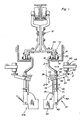
- Fig. 1 illustrates a pair of similar poultry carriers 10 and 10A pivotally suspended from a common overhead conveyor 12 for simultaneous travel along a single conveyor path through one or more drop off stations at which the carriers are supported on fixed track sections 14 by means of roller assemblies 16.
- Side suspension links 18 pivotally interconnect the carriers with the conveyor through the roller shafts 20 associated with the roller assemblies and the pulling links 22 coupled to the conveyor chain by a bar 24.
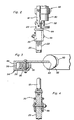
- Each carrier includes an elongated, rod-like body 26 on which a latch element 28 is slidably mounted, externally, by means of upper and lower loops 30 and 32.
- the latch element is gravitationally biased to a downward latched position as shown with its lower end 34 received within a notch 36 of a counterweight plate 38 pivotally mounted on the carrier body by a pivot 40.
- a hook 42 is connected to the counterweight and projects laterally from the geometrical axis of the carrier body 26 at an upward incline as shown, to support a load thereon.
- a release arm 44 projects laterally from the upper end of the latch element on the side of body 26 opposite the hook 42.
- the latch element is displaced upwardly by a force applied to release arm 44 in order to withdraw end 34 from notch 36 and permit the hook to pivot downwardly under load about pivot 40.
- the load will therefore slide off the hook during a load drop off operation as is well-known in the art.
- Such load drop off produces a moment on the carrier body because of the upward latch releasing force applied to the latch element 28 through arm 44 and the downward pivoting of hook 42.
- This load drop off moment tends to tilt the carrier body in the same angular direction as displacement of hook 42 so as to accelerate and insure drop off of the load.
- Each mechanism 48 includes a fluid cylinder or electromagnetic device 50 that is fixedly mounted in laterally spaced relation to the common conveyor path. Because of space limitation and mounting requirements, the power operated devices 50 are located on the outside of the carriers 10 and 10A rather than between the carriers. Further, the devices 50 are operatively aligned so that the plungers 52 engage force transfer elements 54 pivotally mounted by pivots 56 on the carrier bodies. During a power stroke, each plunger 52 is displaced downwardly to apply an operating force to the element 54 in a direction parallel to the axis of body 26 along which the latch element is displaceable on the opposite side of the body.
- the force transfer element 54 is a lever having opposite end portions 58 and 60, respectively, engaging the latch release arm 44 and the plunger 52. It will therefore be apparent that a downward operating force applied by plunger 52 to the lever element 54 will be transmitted to the latch element as an upward latch releasing force to effect load drop off. A moment is produced by such downward operating force on the carrier body through the intermediate pivot 56 of lever element 54 in the same angular displacement of hook 42 from its latched position.
- the pivot 56 of element 54 and pivot 40 of hook 42 substantially intersect the axis of body 26 perpendicular thereto, as does the pivot 62 between the body 26 and the side suspension link 18.
Landscapes
- Engineering & Computer Science (AREA)
- Life Sciences & Earth Sciences (AREA)
- Wood Science & Technology (AREA)
- Zoology (AREA)
- Food Science & Technology (AREA)
- Mechanical Engineering (AREA)
- Processing Of Meat And Fish (AREA)
- Feed For Specific Animals (AREA)
- Lock And Its Accessories (AREA)
Claims (7)
Priority Applications (3)
| Application Number | Priority Date | Filing Date | Title |
|---|---|---|---|
| EP82304493A EP0102420B1 (de) | 1982-08-25 | 1982-08-25 | Entriegelungsmechanismus für Geflügelhaltevorrichtung |
| DE8282304493T DE3276464D1 (en) | 1982-08-25 | 1982-08-25 | Latch release system for poultry carriers |
| AT82304493T ATE27532T1 (de) | 1982-08-25 | 1982-08-25 | Entriegelungsmechanismus fuer gefluegelhaltevorrichtung. |
Applications Claiming Priority (1)
| Application Number | Priority Date | Filing Date | Title |
|---|---|---|---|
| EP82304493A EP0102420B1 (de) | 1982-08-25 | 1982-08-25 | Entriegelungsmechanismus für Geflügelhaltevorrichtung |
Publications (2)
| Publication Number | Publication Date |
|---|---|
| EP0102420A1 EP0102420A1 (de) | 1984-03-14 |
| EP0102420B1 true EP0102420B1 (de) | 1987-06-03 |
Family
ID=8189752
Family Applications (1)
| Application Number | Title | Priority Date | Filing Date |
|---|---|---|---|
| EP82304493A Expired EP0102420B1 (de) | 1982-08-25 | 1982-08-25 | Entriegelungsmechanismus für Geflügelhaltevorrichtung |
Country Status (3)
| Country | Link |
|---|---|
| EP (1) | EP0102420B1 (de) |
| AT (1) | ATE27532T1 (de) |
| DE (1) | DE3276464D1 (de) |
Family Cites Families (8)
| Publication number | Priority date | Publication date | Assignee | Title |
|---|---|---|---|---|
| DE268588C (de) * | ||||
| US3032172A (en) * | 1960-06-24 | 1962-05-01 | Wallace H Jerome | Tripping hook |
| US3376600A (en) * | 1966-02-01 | 1968-04-09 | Internat Agri Systems Inc | Mechanical discharge shackle for fowls and the like |
| US3402675A (en) * | 1966-05-23 | 1968-09-24 | My T Veyor Corp | Suspended carrier despatch station and tripper |
| US4022338A (en) * | 1976-07-12 | 1977-05-10 | Laursen Milton P | Conveyor loader device |
| GB2041314A (en) * | 1979-02-09 | 1980-09-10 | Brockhouse Finspa Handling Ltd | Selective Discharge of Conveyors |
| US4317258A (en) * | 1980-06-12 | 1982-03-02 | W. F. Altenpohl, Inc. | Side suspension conveyor system for poultry |
| US4351087A (en) * | 1981-03-18 | 1982-09-28 | Altenpohl W F | Latch release system for poultry carriers |
-
1982
- 1982-08-25 AT AT82304493T patent/ATE27532T1/de not_active IP Right Cessation
- 1982-08-25 EP EP82304493A patent/EP0102420B1/de not_active Expired
- 1982-08-25 DE DE8282304493T patent/DE3276464D1/de not_active Expired
Also Published As
| Publication number | Publication date |
|---|---|
| DE3276464D1 (en) | 1987-07-09 |
| ATE27532T1 (de) | 1987-06-15 |
| EP0102420A1 (de) | 1984-03-14 |
Similar Documents
| Publication | Publication Date | Title |
|---|---|---|
| US4351087A (en) | Latch release system for poultry carriers | |
| CA2066301C (en) | Automotive body panel handling apparatus | |
| US5090555A (en) | Conveyor of connected carriages | |
| US4498578A (en) | Easy-drop sizing carrier for poultry | |
| EP1106541A1 (de) | Förderanlage mit förderwagen | |
| US3642130A (en) | Modular weight-sorting assembly for conveyors | |
| JPH0911062A (ja) | ライン同期装置 | |
| US5257899A (en) | Transfer feeder | |
| US6161483A (en) | Accumulator mechanism for detaching trolleys from drive chains in power and free conveyor system | |
| EP0102420A1 (de) | Entriegelungsmechanismus für Geflügelhaltevorrichtung | |
| US4646646A (en) | Overhead trolley track switch | |
| CA1191809A (en) | Latch release system for poultry carriers | |
| US4412620A (en) | Plural hook poultry grading carrier system | |
| GB2077681A (en) | Side suspensions conveyor system for poultry | |
| US5526753A (en) | Storage apparatus for a storage conveyor | |
| US3913966A (en) | Tongs for suspending glass | |
| US6823987B2 (en) | Conveyor for containers | |
| CZ212396A3 (en) | Transfer device | |
| US4441606A (en) | Accumulating transfer unit | |
| JP2627203B2 (ja) | ハンガー利用の搬送装置 | |
| JPH0617787Y2 (ja) | 基板搬送装置 | |
| US3643790A (en) | Nonjam lead-on track for conveyor systems | |
| CN213444936U (zh) | 治具控位装置 | |
| WO2000068057A1 (en) | Power and free conveyer system using a towing cable | |
| CN214340518U (zh) | 一种鞋加工设备的鞋体连续传送机构 |
Legal Events
| Date | Code | Title | Description |
|---|---|---|---|
| PUAI | Public reference made under article 153(3) epc to a published international application that has entered the european phase |
Free format text: ORIGINAL CODE: 0009012 |
|
| AK | Designated contracting states |
Designated state(s): AT BE CH DE FR GB IT LI LU NL SE |
|
| 17P | Request for examination filed |
Effective date: 19840822 |
|
| GRAA | (expected) grant |
Free format text: ORIGINAL CODE: 0009210 |
|
| AK | Designated contracting states |
Kind code of ref document: B1 Designated state(s): AT BE CH DE FR GB IT LI LU NL SE |
|
| PG25 | Lapsed in a contracting state [announced via postgrant information from national office to epo] |
Ref country code: NL Effective date: 19870603 Ref country code: LI Effective date: 19870603 Ref country code: IT Free format text: LAPSE BECAUSE OF FAILURE TO SUBMIT A TRANSLATION OF THE DESCRIPTION OR TO PAY THE FEE WITHIN THE PRESCRIBED TIME-LIMIT;WARNING: LAPSES OF ITALIAN PATENTS WITH EFFECTIVE DATE BEFORE 2007 MAY HAVE OCCURRED AT ANY TIME BEFORE 2007. THE CORRECT EFFECTIVE DATE MAY BE DIFFERENT FROM THE ONE RECORDED. Effective date: 19870603 Ref country code: FR Free format text: THE PATENT HAS BEEN ANNULLED BY A DECISION OF A NATIONAL AUTHORITY Effective date: 19870603 Ref country code: CH Effective date: 19870603 Ref country code: BE Effective date: 19870603 Ref country code: AT Effective date: 19870603 |
|
| REF | Corresponds to: |
Ref document number: 27532 Country of ref document: AT Date of ref document: 19870615 Kind code of ref document: T |
|
| PG25 | Lapsed in a contracting state [announced via postgrant information from national office to epo] |
Ref country code: SE Effective date: 19870630 |
|
| REF | Corresponds to: |
Ref document number: 3276464 Country of ref document: DE Date of ref document: 19870709 |
|
| PG25 | Lapsed in a contracting state [announced via postgrant information from national office to epo] |
Ref country code: LU Free format text: LAPSE BECAUSE OF NON-PAYMENT OF DUE FEES Effective date: 19870831 |
|
| REG | Reference to a national code |
Ref country code: CH Ref legal event code: PL |
|
| EN | Fr: translation not filed | ||
| NLV1 | Nl: lapsed or annulled due to failure to fulfill the requirements of art. 29p and 29m of the patents act | ||
| PLBE | No opposition filed within time limit |
Free format text: ORIGINAL CODE: 0009261 |
|
| STAA | Information on the status of an ep patent application or granted ep patent |
Free format text: STATUS: NO OPPOSITION FILED WITHIN TIME LIMIT |
|
| PG25 | Lapsed in a contracting state [announced via postgrant information from national office to epo] |
Ref country code: DE Effective date: 19880503 |
|
| 26N | No opposition filed | ||
| PG25 | Lapsed in a contracting state [announced via postgrant information from national office to epo] |
Ref country code: GB Free format text: LAPSE BECAUSE OF NON-PAYMENT OF DUE FEES Effective date: 19880825 |
|
| GBPC | Gb: european patent ceased through non-payment of renewal fee |