EP0102479A2 - Réchauffeur à écoulement continu pour métaux en fusion - Google Patents
Réchauffeur à écoulement continu pour métaux en fusion Download PDFInfo
- Publication number
- EP0102479A2 EP0102479A2 EP83106697A EP83106697A EP0102479A2 EP 0102479 A2 EP0102479 A2 EP 0102479A2 EP 83106697 A EP83106697 A EP 83106697A EP 83106697 A EP83106697 A EP 83106697A EP 0102479 A2 EP0102479 A2 EP 0102479A2
- Authority
- EP
- European Patent Office
- Prior art keywords
- crucible
- furnace
- induction
- melt
- inlet
- Prior art date
- Legal status (The legal status is an assumption and is not a legal conclusion. Google has not performed a legal analysis and makes no representation as to the accuracy of the status listed.)
- Withdrawn
Links
- 239000002184 metal Substances 0.000 title claims abstract description 9
- 229910052751 metal Inorganic materials 0.000 title claims abstract description 9
- 150000002739 metals Chemical class 0.000 title abstract 2
- 230000006698 induction Effects 0.000 claims abstract description 25
- 239000000155 melt Substances 0.000 claims abstract description 13
- 210000004894 snout Anatomy 0.000 abstract description 3
- 238000010438 heat treatment Methods 0.000 description 5
- 230000003014 reinforcing effect Effects 0.000 description 4
- IJGRMHOSHXDMSA-UHFFFAOYSA-N Atomic nitrogen Chemical compound N#N IJGRMHOSHXDMSA-UHFFFAOYSA-N 0.000 description 2
- OKTJSMMVPCPJKN-UHFFFAOYSA-N Carbon Chemical compound [C] OKTJSMMVPCPJKN-UHFFFAOYSA-N 0.000 description 2
- 230000000694 effects Effects 0.000 description 2
- 230000009970 fire resistant effect Effects 0.000 description 2
- 238000009413 insulation Methods 0.000 description 2
- 229910045601 alloy Inorganic materials 0.000 description 1
- 239000000956 alloy Substances 0.000 description 1
- 238000005275 alloying Methods 0.000 description 1
- 229910052799 carbon Inorganic materials 0.000 description 1
- 230000006835 compression Effects 0.000 description 1
- 238000007906 compression Methods 0.000 description 1
- 238000001816 cooling Methods 0.000 description 1
- 230000008020 evaporation Effects 0.000 description 1
- 238000001704 evaporation Methods 0.000 description 1
- 239000007789 gas Substances 0.000 description 1
- 229910002804 graphite Inorganic materials 0.000 description 1
- 239000010439 graphite Substances 0.000 description 1
- 230000008018 melting Effects 0.000 description 1
- 238000002844 melting Methods 0.000 description 1
- 238000005272 metallurgy Methods 0.000 description 1
- 229910052757 nitrogen Inorganic materials 0.000 description 1
- 230000005855 radiation Effects 0.000 description 1
- 238000010992 reflux Methods 0.000 description 1
- 230000003068 static effect Effects 0.000 description 1
- 238000003756 stirring Methods 0.000 description 1
- 238000009489 vacuum treatment Methods 0.000 description 1
Images
Classifications
-
- H—ELECTRICITY
- H05—ELECTRIC TECHNIQUES NOT OTHERWISE PROVIDED FOR
- H05B—ELECTRIC HEATING; ELECTRIC LIGHT SOURCES NOT OTHERWISE PROVIDED FOR; CIRCUIT ARRANGEMENTS FOR ELECTRIC LIGHT SOURCES, IN GENERAL
- H05B6/00—Heating by electric, magnetic or electromagnetic fields
- H05B6/02—Induction heating
- H05B6/22—Furnaces without an endless core
- H05B6/24—Crucible furnaces
Definitions
- the invention relates to a continuous flow heater for molten metal, e.g. an induction crucible furnace to maintain or increase the temperature level of a molten metal.
- the induction channel furnace is ideal for continuous operation. Batch operation with the induction channel furnace, on the other hand, is difficult for larger units and outputs, since the associated temperature fluctuations, particularly in the refractory lining of the inductors, lead to considerable problems. Accordingly, changing alloys and quality requires considerable effort.
- the induction crucible furnace has already been used for batch heating. Special designs of induction crucible furnaces have also been used for continuous heating.
- a fireproof-lined pipe was fed through the tilting bearing of the induction crucible furnace and was intended to supply the melt to be heated. The discharge took place via an open snout or a siphon by tilting the induction crucible furnace.
- the melt is supplied through a slot in the lid. In both embodiments, it was necessary to change the crucible at shorter intervals than with normal induction crucible furnaces. Significant signs of wear mostly occurred in the areas of the crucible wall.
- the object of the invention is an induction crucible furnace to create, in which the life of the crucible corresponds approximately to the life of the crucible in a normal induction crucible furnace.
- the feed of the melt to the crucible furnace is arranged below the bath level in the furnace.
- One possibility for this is to provide the inlet in the bottom of the crucible.
- the spout can be made through the snout, but it can also be provided in the bottom of the crucible.
- Such an induction crucible furnace with an inlet and outlet in the bottom is particularly suitable if the treatment vessel is also to be placed under vacuum.
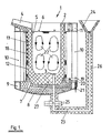
- Fig. 1 shows an induction crucible furnace 1 with a cylindrical crucible 2, which is provided with an inlet 3 for the melt and a pouring spout 4.
- the crucible 2 is filled with melt 5 up to the bath level 6.
- the crucible 2 stands on a refractory base 7, which is supported on a metallic base plate 8.
- the metallic base plate 8 forms with a lower reinforcing ring 9, vertical struts 10 and an upper reinforcing ring 11 the furnace frame.
- the reinforcing ring 11 is shaped in the area of the pouring spout 4 so that the pouring spout 4 can be supported on it.
- the crucible 2 is surrounded by a coil insert 12 and 13. Magnetic yokes 18 ensure the magnetic reflux of the lines of force generated in the active coil.
- clamping devices are arranged, which consist of a lever 19, a threaded spindle 20 and a compression spring 21. With the help of this clamping device, the coils 12 and 13 are pressed against the reinforcing ring 11.
- the bath movement generated by the induction is represented by the lines 22.
- the inlet opening 3 is connected to the connecting pipe 23, which leads to the funnel 24, via flanges 25 or the like.
- a fire-resistant lined pipeline was used for this.
- This pipeline is also provided with thermal insulation 26 in order to avoid heat radiation to the outside or excessive cooling of the melt in the pipeline.
- the static bath pressure in the furnace, which corresponds to the bath level 6, and in the feed line or the funnel 24 must be the same. It is therefore possible to influence the bath level 6 in the furnace via the bath level in the funnel 24.
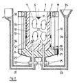
- FIG. 2 shows another embodiment of FIG. 1.
- the outflow opening 30 is arranged here, like the inflow opening 3, in the bottom 27 of the crucible 2.
- This outflow opening 30 is connected to the pouring spout 33 via a connecting line 31, which is connected to the outflow opening via flanges 32.
- a fire-resistant lined pipeline is used is provided on the outside with thermal insulation 34.
- the inlet opening 3 and the outlet opening 30 are close to one another, this does not interfere because the strong stirring effect of the induction current prevents the melt from being directly passed from the inlet to the outlet.
- the corresponding bath movement is also indicated by the lines 22 in this figure.
- the device at the end of the treatment, can be emptied by tilting or, if the induction crucible furnace is not designed to be tiltable, by means of a floor plug, not shown.
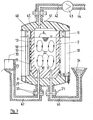
- FIG 3 shows a further embodiment of the invention, in which the crucible 2 is provided with a lid 40 in a vacuum-tight manner and the atmosphere above the bath level 6 can be sucked off through the opening 41 by means of the vacuum pump 43.
- the vacuum pump 43 is connected to the suction opening 41 via the connecting line 42 and the flanges 45.
- At the outlet of the vacuum pump there is a line 44 through which the extracted gases can be discharged.
- This embodiment also has the advantage that the inlet and outlet points 24 and 33 can be deeper than in the embodiment according to FIG. 2. This has the advantage that after treatment, ie after the vacuum has been removed, less residual melt in the treatment unit remains. In addition, of course, are the verb cable lines 46 and 47 shorter.
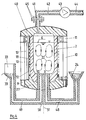
- Fig. 4 shows an embodiment with a one-piece design of the inlet and outlet lines 48 and 49. These are arranged in the part 50, so that a component results.
- This embodiment also has the advantage that the component 50 can be rotated about its vertical and the vertical axis 51 of the crucible furnace, so that the inlet opening 3 and the outlet opening 40 are closed. This component represents a slide.
- the invention is not limited to the exemplary embodiments shown, in particular the inlet can also be designed differently.
Landscapes
- Physics & Mathematics (AREA)
- Electromagnetism (AREA)
- Crucibles And Fluidized-Bed Furnaces (AREA)
Applications Claiming Priority (2)
| Application Number | Priority Date | Filing Date | Title |
|---|---|---|---|
| DE3229367 | 1982-08-06 | ||
| DE19823229367 DE3229367A1 (de) | 1982-08-06 | 1982-08-06 | Durchlauferhitzer fuer schmelzfluessige metalle |
Publications (2)
| Publication Number | Publication Date |
|---|---|
| EP0102479A2 true EP0102479A2 (fr) | 1984-03-14 |
| EP0102479A3 EP0102479A3 (en) | 1984-09-05 |
Family
ID=6170276
Family Applications (1)
| Application Number | Title | Priority Date | Filing Date |
|---|---|---|---|
| EP83106697A Withdrawn EP0102479A3 (en) | 1982-08-06 | 1983-07-08 | Continuous-flow heater for molten metals |
Country Status (4)
| Country | Link |
|---|---|
| US (1) | US4486889A (fr) |
| EP (1) | EP0102479A3 (fr) |
| JP (1) | JPS5944574A (fr) |
| DE (1) | DE3229367A1 (fr) |
Families Citing this family (6)
| Publication number | Priority date | Publication date | Assignee | Title |
|---|---|---|---|---|
| JPH0579769A (ja) * | 1991-09-20 | 1993-03-30 | Fuji Electric Co Ltd | 押さえ蓋を備える高速溶解誘導炉 |
| US6393044B1 (en) * | 1999-11-12 | 2002-05-21 | Inductotherm Corp. | High efficiency induction melting system |
| US20050098294A1 (en) * | 2003-11-12 | 2005-05-12 | Howard Robert W. | Casting device and method |
| US7413590B2 (en) * | 2006-01-11 | 2008-08-19 | Heritage Environmental Services, Llc | Use of an induction furnace for the production of iron from ore |
| US20080130704A1 (en) * | 2006-11-30 | 2008-06-05 | Lapoint Albert E | Electroslag smelting system and method |
| GB2586634B (en) * | 2019-08-30 | 2022-04-20 | Dyson Technology Ltd | Multizone crucible apparatus |
Family Cites Families (6)
| Publication number | Priority date | Publication date | Assignee | Title |
|---|---|---|---|---|
| DE1061003B (de) * | 1958-04-12 | 1959-07-09 | Otto Junker Fa | Kernloser Induktions-Schmelzofen fuer Vakuumbetrieb |
| US3230073A (en) * | 1962-07-20 | 1966-01-18 | Asea Ab | Process for vacuum degassing with electromagnetic stirring |
| US3380511A (en) * | 1964-05-25 | 1968-04-30 | Campbell James Samuel | Apparatus for automatically filling a receptacle |
| US3320348A (en) * | 1964-08-07 | 1967-05-16 | V & V Companies Inc | Induction melting furnace |
| US3700779A (en) * | 1970-07-30 | 1972-10-24 | Est Aciers Fins | Method of treatment of liquid steel under vacuum |
| US3819842A (en) * | 1972-04-24 | 1974-06-25 | Elin Union Ag | Method and furnace for maintaining the temperature level of metal melts |
-
1982
- 1982-08-06 DE DE19823229367 patent/DE3229367A1/de not_active Withdrawn
-
1983
- 1983-07-08 EP EP83106697A patent/EP0102479A3/de not_active Withdrawn
- 1983-08-01 US US06/519,096 patent/US4486889A/en not_active Expired - Fee Related
- 1983-08-05 JP JP58142630A patent/JPS5944574A/ja active Pending
Also Published As
| Publication number | Publication date |
|---|---|
| US4486889A (en) | 1984-12-04 |
| JPS5944574A (ja) | 1984-03-13 |
| DE3229367A1 (de) | 1984-02-09 |
| EP0102479A3 (en) | 1984-09-05 |
Similar Documents
| Publication | Publication Date | Title |
|---|---|---|
| EP0193948B1 (fr) | Dispositif et procédé pour maintenir à température des bains métalliques | |
| WO2000048770A1 (fr) | Procede et dispositif pour produire des pieces coulees en alliages d'aluminium et de magnesium | |
| EP0133925A1 (fr) | Electrode de fond pour un four à arc à courant continu | |
| EP0102479A2 (fr) | Réchauffeur à écoulement continu pour métaux en fusion | |
| DE69407992T2 (de) | Kompakte pfanne zur behandlung von metallschmelze | |
| EP1006205B1 (fr) | Procédé pour la fabrication des alliages homogenes par fusion et refusion | |
| EP1140391B1 (fr) | Procede et dispositif pour regler et/ou maintenir la temperature d'une masse en fusion, en particulier d'acier en fusion lors de la coulee en continu | |
| EP0133931B1 (fr) | Dispositif de refroidissement d'une électrode de fond d'un four à arc à courant continu | |
| DE1433406B2 (de) | Anordnung zum Entgasen von Stahloder Metallschmelzen | |
| DE1960283A1 (de) | Vakuumentgasungsvorrichtung fuer die Verwendung beim Stranggiessen von Metallen und Verfahren zum Stranggiessen von schmelzfluessigem Metall,waehrend es einer Vakuumentgasung unterworfen ist | |
| DE2724489C2 (de) | Metallschmelzofen | |
| DE2501603C3 (fr) | ||
| EP1450974B1 (fr) | Dispositif constitue d'un cuve de coulee pouvant etre chauffee et d'un four-poche | |
| AT204711B (de) | Ofen zum Schmelzen und Gießen unter Vakuum oder Schutzgasatmosphäre | |
| DE1458804B1 (de) | Vorrichtung zur Entgasung von Schmelzen unter Vakuum | |
| DE1458804C (de) | Vorrichtung zur Entgasung von Schmelzen unter Vakuum | |
| DE593834C (de) | Verfahren zur Vakuumbehandlung von Metallen und Legierungen mit Schmelzpunkten ueber 1200íÒ | |
| DE3637065A1 (de) | Pfanne mit beheizungsvorrichtung | |
| DE3221241C2 (de) | Verfahren und Vorrichtung zum Herstellen von gießfertigem Metall | |
| DE2648433A1 (de) | Verbesserung an giess- und stranggiess-induktions-tiegeloefen und an behandlungspfannen | |
| DE647114C (de) | Vorrichtung zum Herstellen dichter Gussbloecke | |
| DE7922196U1 (de) | Vorrichtung zum aufheizen einer giesspfanne | |
| DE2029687A1 (de) | Verfahren zum Abgießen von Metall oder Metallegierungen in Stranggußkokillen | |
| DE3041741C2 (de) | Induktionsrinnenofen | |
| DE1925484A1 (de) | Verfahren bzw. Einrichtung zur Raffination von Metallen |
Legal Events
| Date | Code | Title | Description |
|---|---|---|---|
| PUAI | Public reference made under article 153(3) epc to a published international application that has entered the european phase |
Free format text: ORIGINAL CODE: 0009012 |
|
| AK | Designated contracting states |
Designated state(s): AT BE FR NL SE |
|
| PUAL | Search report despatched |
Free format text: ORIGINAL CODE: 0009013 |
|
| AK | Designated contracting states |
Designated state(s): AT BE FR NL SE |
|
| STAA | Information on the status of an ep patent application or granted ep patent |
Free format text: STATUS: THE APPLICATION IS DEEMED TO BE WITHDRAWN |
|
| 18D | Application deemed to be withdrawn |
Effective date: 19850507 |
|
| RIN1 | Information on inventor provided before grant (corrected) |
Inventor name: DOETSCH, ERWIN, DR., DIPL.-ING. Inventor name: HEGEWALDT, FRITZ, DIPL.-ING. |