EP0102551A2 - Boggie de véhicule à moteur - Google Patents
Boggie de véhicule à moteur Download PDFInfo
- Publication number
- EP0102551A2 EP0102551A2 EP83107849A EP83107849A EP0102551A2 EP 0102551 A2 EP0102551 A2 EP 0102551A2 EP 83107849 A EP83107849 A EP 83107849A EP 83107849 A EP83107849 A EP 83107849A EP 0102551 A2 EP0102551 A2 EP 0102551A2
- Authority
- EP
- European Patent Office
- Prior art keywords
- bogie
- vehicle according
- induction motor
- linear induction
- pin
- Prior art date
- Legal status (The legal status is an assumption and is not a legal conclusion. Google has not performed a legal analysis and makes no representation as to the accuracy of the status listed.)
- Granted
Links
Images

Classifications
-
- B—PERFORMING OPERATIONS; TRANSPORTING
- B60—VEHICLES IN GENERAL
- B60L—PROPULSION OF ELECTRICALLY-PROPELLED VEHICLES; SUPPLYING ELECTRIC POWER FOR AUXILIARY EQUIPMENT OF ELECTRICALLY-PROPELLED VEHICLES; ELECTRODYNAMIC BRAKE SYSTEMS FOR VEHICLES IN GENERAL; MAGNETIC SUSPENSION OR LEVITATION FOR VEHICLES; MONITORING OPERATING VARIABLES OF ELECTRICALLY-PROPELLED VEHICLES; ELECTRIC SAFETY DEVICES FOR ELECTRICALLY-PROPELLED VEHICLES
- B60L13/00—Electric propulsion for monorail vehicles, suspension vehicles or rack railways; Magnetic suspension or levitation for vehicles
- B60L13/03—Electric propulsion by linear motors
- B60L13/035—Suspension of the vehicle-borne motorparts
-
- B—PERFORMING OPERATIONS; TRANSPORTING
- B60—VEHICLES IN GENERAL
- B60L—PROPULSION OF ELECTRICALLY-PROPELLED VEHICLES; SUPPLYING ELECTRIC POWER FOR AUXILIARY EQUIPMENT OF ELECTRICALLY-PROPELLED VEHICLES; ELECTRODYNAMIC BRAKE SYSTEMS FOR VEHICLES IN GENERAL; MAGNETIC SUSPENSION OR LEVITATION FOR VEHICLES; MONITORING OPERATING VARIABLES OF ELECTRICALLY-PROPELLED VEHICLES; ELECTRIC SAFETY DEVICES FOR ELECTRICALLY-PROPELLED VEHICLES
- B60L2200/00—Type of vehicles
- B60L2200/26—Rail vehicles
Definitions
- the present invention relates to a vehicle construction and, more particularly, to a motor bogie or carriage for a vehicle powered or driven by a linear motor means.
- a linear motor means is directly suspended from a shaft of the vehicle bogie or carriage.
- pairs of suspension means such as, for example, mechanical journal bearings are mounted on shafts of the vehicle, with a primary apparatus of a linear induction motor, including an iron core and a coil unit wound on the core, being suspended. from the suspensions under a floor of the motor vehicle, and with the secondary means of the linear induction motor such as, for example, a reaction plate, being disposed on a vehicle support means such as the ground.
- the secondary apparatus includes an integral iron plate and aluminum plate.
- the aim underlying the present invention essentially resides in providing a bogie or carnage for a linear induction motor driven vehicle which improves an ability of the vehicle to follow the vehicle guide rails.
- a linear induction motor powered vehicle wherein a linear.motor means is suspended from at least one beam means bridged or suspended between a pair of suspension means mounted on a shaft of the bogie or carriage.
- At least one universal or flexible joint means is provided for coupling the beam to the linear motor means.
- the beam means may, in accordance with the present invention, have a substantially U-shaped cross-sectional configuration and be .disposed so as to surround the shafts of wheel assemblies of the vehicle bogie or carriage.
- the suspending means are disposed between respective wheel means of the wheel assembly and the linear motor means.
- the universal joint means includes a pin means mounted on the beam means, with the pin means having large diameter outer ends which progressively become smaller or taper in a direction of a center thereof, and with an annular resilient member being press fitted and configured to accommodate the taper of the pin means.
- a receiving means is provided having an opening configured so as to enable a press fitting about a periphery of the resilient means, with the linear motor means being fixed to the receiving means.
- the linear motor means may, in accordance with the present invention, include a coil means wound around a core of, for example, iron.
- Another object of the present invention resides in providing a bogie or carriage for a linear induction motor powered vehicle which reduces the bending moments applied to the shaft means of the wheel assemblies of the vehicle.
- a still further object of-the present invention resides in providing the bogie or carriage for a linear induction motor driven vehicle which ensures a stable operation of the linear induction motor.
- Yet another object of the present invention resides in providing a carriage or bogie for a linear induction motor driven vehicle which is simple in construction and therefore relatively inexpensive to manufacture.
- a further object of the present invention resides in providing a carnage or bogie for a linear induction motor driven vehicle which functions realiably under all operating conditions.
- wheel assemblies generally designated by the reference numerals 10, 12 include shafts 14, 16 having pairs of wheels 18, 19 and 20, 21 mounted at respective ends of the shafts 14, 16.
- mechanical bearing block means 22 are mounted at respective ends of the shafts 14, 16 and a bogie or carriage frame 24 is mounted on the bearing block means 22, with suspension spring means 26 being inserted or interposed between the frame 24 and the bearing block means 22.
- suspension spring means 26 being inserted or interposed between the frame 24 and the bearing block means 22.
- pairs of suspension means 28, 30 and 32, 34 constructed as, for example, mechanical bearing block means, are mounted at respective ends of the shafts 14, 16 at a position inside of the wheels 18, 19 and 20, 21.
- a beam fashioned, for example, as U-shaped pipe means 36, 38, respectively surrounding the shafts 14, 16 is bridged between the respective pairs of suspension means 28, 30 and 32, 34.
- the U-shaped pipe means 36, 38 are rigidly bonded to the suspension means 28, 30 and 32, 34 by, for example, welding or the like.
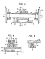
- tapered pins 40, 42 are disposed or mounted in openings 48, 50 provided in receiving members 52, 54 respectively disposed in a central area of the pipe means 36, 38, with annular resilient members 44, 46 such as, for example, cured synthetic rubber members, being press fitted on a peripheral outer surface of the tapered pins 40, 42.
- the openings 48, 50 provided in the receiving members 52, 54 are configured or sized so as to enable a press fitting of the resilient members 44, 46 therein.
- the tapered pins 40, 42, annular resilient members 44, 46, and receiving members 52, 54 respectively form universal or flexible joint means generally designated by the reference numerals 55, 56.
- the receiving members 52, 54 are fixed to a bracket means 57, 58 of a supporting frame 59.
- An iron core 60 and a. coil unit 62, wound on the core 60, are fixed to the supporting frame 59.
- the tapered pin means 40, 42 have a normal taper 66 which is progressively reduced from an outer end thereof toward the center and a reverse taper 68 which progressively increases from the center toward the opposite end of the pin as shown most clearly in Figures 3 and 4.
- the openings 48, 50 and the annular receiving members 52, 54 have tapers 70, 72 corresponding to the tapers 66, 68 of the tapered pin means 40, 42. Therefore, the resilient members 40, 46 have a substantially X-shaped cross-sectional configuration.
- the deformable annular resilient members 40, 46 and the tapered pins 40, 42 allow the shafts 14, 16 to move in lateral and vertical directions as well as rotating in any of three mutually perpendicular planes.
- rotation in a horizontal plane is known as yawing
- in a vertical plane perpendicular to the direction of travel is know as rowing
- in a vertical plane parallel to the direction of travel is know as pitching.
- the position of the suspending means 28, 30 and 32, 34 is not limited and may be varied to other positions disposed between the respective wheels 18, 19 and 20, 21 and the linear induction motor means 74. Moreover, since all of the weight of the linear motor apparatus is supported by the beam or U-shaped pipes 36, 38, the bending moments to the shafts 14, 16 are reduced. Furthermore, the U-shaped cross sectional configuration of the beams provide a high resistance to the bending moments.
- the suspension arrangement of the present invention may be used to support a reaction plate of the linear induction motor 76, with the linear induction motor then being mounted in the support means and/or guide rail for the motor vehicle.
Landscapes
- Engineering & Computer Science (AREA)
- Physics & Mathematics (AREA)
- Electromagnetism (AREA)
- Power Engineering (AREA)
- Transportation (AREA)
- Mechanical Engineering (AREA)
- Control Of Vehicles With Linear Motors And Vehicles That Are Magnetically Levitated (AREA)
- Linear Motors (AREA)
Applications Claiming Priority (2)
| Application Number | Priority Date | Filing Date | Title |
|---|---|---|---|
| JP137365/82 | 1982-08-09 | ||
| JP57137365A JPS5929561A (ja) | 1982-08-09 | 1982-08-09 | リニアモ−タ駆動車両用台車 |
Publications (3)
| Publication Number | Publication Date |
|---|---|
| EP0102551A2 true EP0102551A2 (fr) | 1984-03-14 |
| EP0102551A3 EP0102551A3 (en) | 1987-09-30 |
| EP0102551B1 EP0102551B1 (fr) | 1991-01-30 |
Family
ID=15196971
Family Applications (1)
| Application Number | Title | Priority Date | Filing Date |
|---|---|---|---|
| EP83107849A Expired EP0102551B1 (fr) | 1982-08-09 | 1983-08-09 | Boggie de véhicule à moteur |
Country Status (5)
| Country | Link |
|---|---|
| US (1) | US4593625A (fr) |
| EP (1) | EP0102551B1 (fr) |
| JP (1) | JPS5929561A (fr) |
| CA (1) | CA1203125A (fr) |
| DE (1) | DE3382143D1 (fr) |
Cited By (5)
| Publication number | Priority date | Publication date | Assignee | Title |
|---|---|---|---|---|
| EP0195644A1 (fr) * | 1985-03-18 | 1986-09-24 | Shinko Electric Co. Ltd. | Appareil à chariot |
| DE4322074A1 (de) * | 1993-07-02 | 1995-01-26 | Magnetbahn Gmbh | Linearmotor mit als Fahrzeug ausgebildetem Läufer |
| EP1803604A2 (fr) | 2005-12-23 | 2007-07-04 | Bombardier Transportation GmbH | Bogie ferroviaire équipé d'un moteur linéaire à induction |
| CN103171457A (zh) * | 2011-12-22 | 2013-06-26 | 邦巴尔迪尔运输有限公司 | 用于次级lim轨道部分的支撑结构 |
| LT6694B (lt) | 2019-01-31 | 2020-01-27 | Fokin Aleksandr | Universalus geležinkelio vežimėlis su judėjimo ritinėliais |
Families Citing this family (11)
| Publication number | Priority date | Publication date | Assignee | Title |
|---|---|---|---|---|
| FR2604964B1 (fr) * | 1986-10-14 | 1993-12-31 | Matra Transport | Essieu a guidage magnetique pour vehicule sur voie ferree |
| FR2754230B1 (fr) * | 1996-10-07 | 2003-09-26 | Gec Alsthom Transport Sa | Chassis de bogie articule et bogie articule comportant un tel chassis |
| RU2206465C1 (ru) * | 2001-12-28 | 2003-06-20 | Московский государственный университет путей сообщения | Транспортная система с линейным двигателем "транслид-миит" |
| US6732658B1 (en) * | 2003-07-14 | 2004-05-11 | John B. Shaw | Transit car propelled by multiple pairs of magnetic linear motors |
| CN102079316B (zh) * | 2010-09-07 | 2012-08-08 | 南车青岛四方机车车辆股份有限公司 | 轨道车辆直线电机转向架及其制造方法 |
| CN102195394B (zh) * | 2010-12-27 | 2012-11-21 | 南车青岛四方机车车辆股份有限公司 | 轨道车辆直线电机悬挂和高度调整装置及其方法 |
| US9701319B2 (en) | 2013-08-12 | 2017-07-11 | Gonzalo Duran Ariza | Transportation systems |
| CN104895904B (zh) * | 2015-06-12 | 2017-10-03 | 中车青岛四方机车车辆股份有限公司 | 一种安装有防松止转垫片的直线电机转向架 |
| FR3049252B1 (fr) * | 2016-03-25 | 2018-04-20 | Alstom Transport Technologies | Bogie comprenant une liaison rigide entre les boites d'essieu, et vehicule ferroviaire associe |
| CA2936722C (fr) * | 2016-07-19 | 2017-03-07 | Bombardier Transportation Gmbh | Bogie avec support de moteur pour moteur lineaire a induction |
| CN110435676B (zh) * | 2019-08-07 | 2024-05-07 | 重庆交通大学 | 直线电机驱动跨座式单轨车辆 |
Family Cites Families (8)
| Publication number | Priority date | Publication date | Assignee | Title |
|---|---|---|---|---|
| US573823A (en) * | 1896-12-22 | lefpler | ||
| BE537731A (fr) * | 1952-11-19 | |||
| GB997306A (en) * | 1961-11-17 | 1965-07-07 | Metalastik Ltd | Improvements in or relating to railway vehicles |
| FR1559018A (fr) * | 1967-12-28 | 1969-03-07 | ||
| US3602149A (en) * | 1969-03-28 | 1971-08-31 | Gen Steel Ind Inc | Linear motor driven railway vehicle truck |
| FR2194067B1 (fr) * | 1972-07-26 | 1976-05-14 | Moyse Sa | |
| DE2443832A1 (de) * | 1974-09-13 | 1976-03-25 | Knorr Bremse Gmbh | Aufhaengevorrichtung fuer schienenbremsmagnete |
| CA1078936A (fr) * | 1977-11-30 | 1980-06-03 | George Sobolewski | Bogie et ensemble de propulsion a moteur lineaire |
-
1982
- 1982-08-09 JP JP57137365A patent/JPS5929561A/ja active Granted
-
1983
- 1983-08-09 EP EP83107849A patent/EP0102551B1/fr not_active Expired
- 1983-08-09 DE DE8383107849T patent/DE3382143D1/de not_active Expired - Lifetime
- 1983-08-09 CA CA000434241A patent/CA1203125A/fr not_active Expired
- 1983-08-09 US US06/521,549 patent/US4593625A/en not_active Expired - Fee Related
Cited By (5)
| Publication number | Priority date | Publication date | Assignee | Title |
|---|---|---|---|---|
| EP0195644A1 (fr) * | 1985-03-18 | 1986-09-24 | Shinko Electric Co. Ltd. | Appareil à chariot |
| DE4322074A1 (de) * | 1993-07-02 | 1995-01-26 | Magnetbahn Gmbh | Linearmotor mit als Fahrzeug ausgebildetem Läufer |
| EP1803604A2 (fr) | 2005-12-23 | 2007-07-04 | Bombardier Transportation GmbH | Bogie ferroviaire équipé d'un moteur linéaire à induction |
| CN103171457A (zh) * | 2011-12-22 | 2013-06-26 | 邦巴尔迪尔运输有限公司 | 用于次级lim轨道部分的支撑结构 |
| LT6694B (lt) | 2019-01-31 | 2020-01-27 | Fokin Aleksandr | Universalus geležinkelio vežimėlis su judėjimo ritinėliais |
Also Published As
| Publication number | Publication date |
|---|---|
| EP0102551B1 (fr) | 1991-01-30 |
| US4593625A (en) | 1986-06-10 |
| EP0102551A3 (en) | 1987-09-30 |
| JPS5929561A (ja) | 1984-02-16 |
| JPH0137310B2 (fr) | 1989-08-07 |
| DE3382143D1 (de) | 1991-03-07 |
| CA1203125A (fr) | 1986-04-15 |
Similar Documents
| Publication | Publication Date | Title |
|---|---|---|
| EP0102551A2 (fr) | Boggie de véhicule à moteur | |
| US3703215A (en) | Independent front suspension system for a front wheel drive automobile | |
| EP0931684B1 (fr) | Véhicule à propulsion électrique | |
| US5098068A (en) | Lifting machinery | |
| US4398468A (en) | Railway propulsion system suspension | |
| US20200385032A1 (en) | Elastic bushing device of traction device and railcar bogie | |
| US5941174A (en) | Motorized axle having wheels that rotate independently | |
| US3515405A (en) | Axle suspension system for transit vehicles | |
| US1813140A (en) | Railway motor suspension | |
| US4249627A (en) | Chassis and suspension arrangement for motor vehicles | |
| JPH08253147A (ja) | 鉄道車両の軌間可変台車 | |
| EP0138764A2 (fr) | Dispositif de palier pour essieux | |
| EP0571961A1 (fr) | Bogie pour un véhicule ferroviaire avec moteurs directs et réducteurs suspendus du châssis | |
| US2987013A (en) | Vehicles | |
| US3092040A (en) | Monorail constructions | |
| US2336661A (en) | Rail-car truck | |
| US6253686B1 (en) | Power puller motor bogie | |
| KR102849191B1 (ko) | 차동 구동 디바이스 및 자동 가이드 수송 차량 | |
| US2290643A (en) | Railway truck construction | |
| EP0086299A2 (fr) | Systèmes de transmission pour véhicules | |
| JPS6357269B2 (fr) | ||
| EP3674165B1 (fr) | Bogie de locomotive ayant une géométrie anti-tangage | |
| US2203290A (en) | Motor vehicle | |
| US5117709A (en) | Rear longitudinal transmission for vehicle with transverse engine and four driven wheels | |
| JPH0339630Y2 (fr) |
Legal Events
| Date | Code | Title | Description |
|---|---|---|---|
| PUAI | Public reference made under article 153(3) epc to a published international application that has entered the european phase |
Free format text: ORIGINAL CODE: 0009012 |
|
| 17P | Request for examination filed |
Effective date: 19830816 |
|
| AK | Designated contracting states |
Designated state(s): DE FR |
|
| PUAL | Search report despatched |
Free format text: ORIGINAL CODE: 0009013 |
|
| AK | Designated contracting states |
Kind code of ref document: A3 Designated state(s): DE FR |
|
| 17Q | First examination report despatched |
Effective date: 19891218 |
|
| GRAA | (expected) grant |
Free format text: ORIGINAL CODE: 0009210 |
|
| AK | Designated contracting states |
Kind code of ref document: B1 Designated state(s): DE FR |
|
| REF | Corresponds to: |
Ref document number: 3382143 Country of ref document: DE Date of ref document: 19910307 |
|
| ET | Fr: translation filed | ||
| PLBE | No opposition filed within time limit |
Free format text: ORIGINAL CODE: 0009261 |
|
| STAA | Information on the status of an ep patent application or granted ep patent |
Free format text: STATUS: NO OPPOSITION FILED WITHIN TIME LIMIT |
|
| 26N | No opposition filed | ||
| PGFP | Annual fee paid to national office [announced via postgrant information from national office to epo] |
Ref country code: FR Payment date: 19970618 Year of fee payment: 15 |
|
| PGFP | Annual fee paid to national office [announced via postgrant information from national office to epo] |
Ref country code: DE Payment date: 19970930 Year of fee payment: 15 |
|
| PG25 | Lapsed in a contracting state [announced via postgrant information from national office to epo] |
Ref country code: FR Free format text: LAPSE BECAUSE OF NON-PAYMENT OF DUE FEES Effective date: 19990430 |
|
| PG25 | Lapsed in a contracting state [announced via postgrant information from national office to epo] |
Ref country code: DE Free format text: LAPSE BECAUSE OF NON-PAYMENT OF DUE FEES Effective date: 19990601 |
|
| REG | Reference to a national code |
Ref country code: FR Ref legal event code: ST |