EP0102583A1 - Table de travail de coin, notamment pour travaux de bureau - Google Patents
Table de travail de coin, notamment pour travaux de bureau Download PDFInfo
- Publication number
- EP0102583A1 EP0102583A1 EP83108294A EP83108294A EP0102583A1 EP 0102583 A1 EP0102583 A1 EP 0102583A1 EP 83108294 A EP83108294 A EP 83108294A EP 83108294 A EP83108294 A EP 83108294A EP 0102583 A1 EP0102583 A1 EP 0102583A1
- Authority
- EP
- European Patent Office
- Prior art keywords
- corner
- worktop
- work table
- table according
- support
- Prior art date
- Legal status (The legal status is an assumption and is not a legal conclusion. Google has not performed a legal analysis and makes no representation as to the accuracy of the status listed.)
- Granted
Links
- 238000003780 insertion Methods 0.000 claims description 10
- 230000037431 insertion Effects 0.000 claims description 10
- 230000000284 resting effect Effects 0.000 claims 1
- 238000010276 construction Methods 0.000 description 5
- 229920001821 foam rubber Polymers 0.000 description 3
- 208000027418 Wounds and injury Diseases 0.000 description 2
- 230000006378 damage Effects 0.000 description 2
- 229920001971 elastomer Polymers 0.000 description 2
- 208000014674 injury Diseases 0.000 description 2
- 238000005452 bending Methods 0.000 description 1
- 230000015572 biosynthetic process Effects 0.000 description 1
- 238000006243 chemical reaction Methods 0.000 description 1
- 230000001427 coherent effect Effects 0.000 description 1
- 239000002131 composite material Substances 0.000 description 1
- 230000001419 dependent effect Effects 0.000 description 1
- 238000004519 manufacturing process Methods 0.000 description 1
- 239000002184 metal Substances 0.000 description 1
- 239000004033 plastic Substances 0.000 description 1
- 125000006850 spacer group Chemical group 0.000 description 1
- 238000003466 welding Methods 0.000 description 1
- 239000002023 wood Substances 0.000 description 1
Images


Classifications
-
- A—HUMAN NECESSITIES
- A47—FURNITURE; DOMESTIC ARTICLES OR APPLIANCES; COFFEE MILLS; SPICE MILLS; SUCTION CLEANERS IN GENERAL
- A47B—TABLES; DESKS; OFFICE FURNITURE; CABINETS; DRAWERS; GENERAL DETAILS OF FURNITURE
- A47B21/00—Tables or desks for office equipment, e.g. typewriters, keyboards
- A47B21/06—Tables or desks for office equipment, e.g. typewriters, keyboards characterised by means for holding, fastening or concealing cables
-
- A—HUMAN NECESSITIES
- A47—FURNITURE; DOMESTIC ARTICLES OR APPLIANCES; COFFEE MILLS; SPICE MILLS; SUCTION CLEANERS IN GENERAL
- A47B—TABLES; DESKS; OFFICE FURNITURE; CABINETS; DRAWERS; GENERAL DETAILS OF FURNITURE
- A47B13/00—Details of tables or desks
- A47B13/003—Connecting table tops to underframes
-
- A—HUMAN NECESSITIES
- A47—FURNITURE; DOMESTIC ARTICLES OR APPLIANCES; COFFEE MILLS; SPICE MILLS; SUCTION CLEANERS IN GENERAL
- A47B—TABLES; DESKS; OFFICE FURNITURE; CABINETS; DRAWERS; GENERAL DETAILS OF FURNITURE
- A47B17/00—Writing-tables
- A47B17/03—Writing-tables with substantially horizontally extensible or adjustable parts other than drawers, e.g. leaves
- A47B17/033—Writing-tables with substantially horizontally extensible or adjustable parts other than drawers, e.g. leaves with parts added to the original furniture to enlarge its surface
Definitions
- the invention relates to a corner work table, especially for office work, according to the preamble of.
- the corner worktop should have the shape of a circular section with two straight radii sides and a circular arc side and be supported by a special base.
- the circular work surface of the corner worktop creates a pleasing image and eliminates the risk of injury.
- the corner worktable has its own stable base frame, a stable, composite table construction can only be created by connecting adjacent worktops to the base frame or the corner worktop, whereby independent support devices for the adjacent worktops near the base frame of the corner worktop can be dispensed with. This avoids double support at the joints and advantageously increases the free foot space in this area.
- the corner work table can be seen as an element for upgrading L-shaped or U-shaped larger table versions, but can also be set up and used independently and independently of attached worktops at any time thanks to its own base frame.
- a corner work table 1 is shown, consisting of a base frame 2 and a corner worktop 3 indicated by dashed lines.
- the corner worktop has the shape of a quarter-circle cutout with an edge area as a circular arc section 4 and two connecting sides 5, 6.
- the quarter-circle cutout of the corner worktop 3 does not run to Center point pointed towards, but is also cut out here in a quarter circle 7.
- the length of the connection sides 5, 6 corresponds to the width of the here other worktops to be connected.
- Non-right-angled circular sections could also be used for the corner worktop (to form different table shapes).
- the exact training is shown in Fig. 4.
- the base frame 2 consists of a bottom bracket 8, the bracket ends vertically. stand at the top and form two corner support feet 9, 10.
- the upper ends of the corner support feet 9, 10 are connected by an arcuate support tube 11 which runs parallel to the circular arc 4 of the corner worktop 3.
- the ends of the support tube 11 are open as insertion openings 12, 13.
- two further support feet 14, 15 run vertically downwards and are connected to the bracket 8 on the bottom side.
- the support feet 14, 15 have on their upper side through a further support tube 16 connection which extends in an arc in the direction of the tip of the corner worktop 3 and supports this part of the corner worktop.
- the corner support feet 9 and 10 and the bracket 8 and the support feet 14, 15 and the support tube 16 are preferably bent from a metallic piece of pipe and welded to the base 2 shown.
- the base frame 2 could also be constructed from plastic or wood and from non-tubular parts.
- the base 2 shown is a stable construction with good stability, which supports the corner worktop 3 well in its edge regions and creates a suitable holder for worktops to be built in due to the insertion openings 12, 1 1 3 described in more detail below. It would also be conceivable to provide only one support foot at the apex of the bracket 8, approximately under the quarter circle 7, instead of the support feet 14, 15. However, this would largely nullify the advantageously large foot space that exists for a user of the corner work table from the side of the circular arc, in that a support foot lies in the direction of the outstretched feet would.
- the arrangement of the support feet 14, 15 shown enables the user to extend the legs in between without any hindrance even over the bracket 8.
- the base frame 2 can be produced very simply and inexpensively by bending and welding three round tube sections.
- the base frame 2 is shown with the corner worktop 3 and straight worktops 17, 18 attached to the connecting sides 5, 6.
- the worktop 18 is flat, i. H. attached to the corner worktop 3 without heel, while the worktop 17 is installed in a lowered position compared to the corner worktop 3.
- the lowering is particularly intended for a typewriter space that is lower than the usual work table height.
- the connection and fastening under the worktops is shown in Fig. 5 and is explained in more detail below.
- a round work table is shown, which is composed of two corner work tables 19, 20 and two corner worktops 21, 22.
- the corner worktops 21, 22 are befe on the corner worktables 19, 20 Stigt and are thereby supported by the two bases under the corner work tables 19, 20.
- Arrangements with 4 bases or 3/4-circle arrangements, for example for a column conversion, are of course also possible.
- Fig. 4 shows the edge formation of the corner worktop 3 and its attachment to the base frame 2 or the support tubes 11, 16.
- the corner worktop 3 is pulled down on its outer edge 23 in the region of the circular arc section 4 in a kind of sidebar so that the support tube 11, which is held by a retaining tab 25, is covered. It is also advantageously achieved that a user of the corner work table 1 does not have any metal contact with the support tube 11 or the holding tab 23 from this outer edge side 23.
- the support tube 11 is screwed from below to the corner worktop 3 with the aid of screws 26, a washer 27 adapted to the tube shape being inserted between the corner worktop 3 and the support tube 11 as a spacer.
- the washer 27 serves to bring the support tube 11 into a height position, which allows the correct insertion into a hat profile (see FIG. 7) on the countertop 18 just adjoining it.
- the holding tab 25 By means of the holding tab 25, the support tube 11 is supported towards the edge strip 24 and at the same time the holding tab is extended on the side facing the corner worktop 3 and bent up at its end.
- a foam rubber piece 21 is inserted between this extension 28 and the underside of the corner worktop 3, which fills this space.
- Electrical cables 30 can be clamped between the top of the foam rubber piece 21 and the underside of the corner worktop 3. As a result, a clean cable routing, which does not obstruct the footwell, is achieved under the corner worktop 3 when electrifying a corner worktable or a table group.
- Fig. 5 corresponds to that in Fig. 2, wherein (conceptually) the worktops are lifted off and only drawn in dashed lines, so that the fastening means and the type of fastening between the worktops can be seen.
- the worktop 18 carries on its two longitudinal sides open hat profiles 31, 32.
- the two hat profiles 31, 32 are used when the worktop 18 is not connected to a corner worktable 1 for the insertion and mounting of foot frames, so that the worktop 18 in Framework of an entire furniture system can be used as an independent table.
- only the hat profile 32 is used for fastening to the corner work table 1, into which a support tube piece 33 is inserted and is clamped in the hat profile 32 with the aid of retaining tabs (not shown).
- connection sides 5, 6 of the corner worktop 3 there are also, for the sake of clarity only shown in dashed lines on the connection side 6, angular rails, the vertical legs of which are also flush with the connection sides 5, 6 (the section shown in FIG. 4 is in the middle the corner worktop is guided behind an angle rail so that it cannot be seen).
- the two angle rails are thus with their vertical legs so that the Mounting holes 35 are aligned.
- the two angle rails can thus simply be screwed together, as a result of which an almost seamless, stable and permanent connection between the corner worktop 3 and the worktop 18 is produced in connection with the support tube piece connection 33.
- recesses 36, 37 are provided in the lateral areas of these rails, so that the cables can be easily carried under the worktops.
- the arrangement of the sponge rubber pieces along the carrier tube 11 is illustrated in FIG. 5 with three sponge rubber pieces 38.
- connection between the corner worktop 3 and the lowered worktop 17 is established by a vertically standing support plate 39 with horizontal support arms 40, 41 attached.
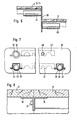
- the support arm 41 is inserted into the insertion opening 12 of the support tube 11, while the support arm 40 is inserted into a hat profile 42 on the underside of the worktop 17.
- Another support arm 43 (see FIG. 7 hidden in FIG. 5) is inserted into a hat profile 44 and fastened there by a clamp holder.
- the connection to the worktop 17 is thus established by the support arms 40, 43 clamped onto the worktop 17.
- the connection to the corner plate 3 or the corner worktable 1 is established once by the support arm 41 and in addition the support plate 39 is screwed towards the tip of the corner worktop 3 with the angle rail (not shown here) of the corner worktop 3.
- FIG. 7 shows a schematic sectional illustration along the line A-A from FIG. 5.
- the support arms 40, 43 projecting from the plane of the drawing are in turn attached to the support plate 39. These support arms 40, 43 protrude into the cut hat profiles 44 and 42 on the worktop 17 (which has been omitted for clarity).
- the support arms 40, 43 are held and clamped in the hat profiles 42, 44 by holding tabs 45, 46 screwed to them. Between the hat profiles 42, 44, the edge-side angle rail 47 of the worktop 17 is shown in dashed lines.
- connection to the corner worktable is indicated by dashed lines.
- the support arm 41 is inserted in the insertion opening 12 of the support tube 11, the other side of the support plate 39 being fastened to the angle bar 47 of the corner worktop 3 by means of a screw connection 48.
- Fig. 8 the flat connection between the corner worktop 3 and the worktop 18 is shown again, the arrangement of the angle rail 34 and an edge-side angle rail 50 on the corner worktop 3 with a screw connection 51 having been omitted in section, omitting the other fastening parts.
- a corner work table was shown, which has good stability and stability with simple manufacture, ensures a large foot space due to the type of substructure and which is good as a component for upgrading to L and U-shaped table constructions due to the described simple and quick fixings suitable is.
Landscapes
- Furniture Connections (AREA)
- Tables And Desks Characterized By Structural Shape (AREA)
- Forklifts And Lifting Vehicles (AREA)
Priority Applications (1)
| Application Number | Priority Date | Filing Date | Title |
|---|---|---|---|
| AT83108294T ATE23660T1 (de) | 1982-08-27 | 1983-08-23 | Eckarbeitstisch, insbesondere fuer bueroarbeiten. |
Applications Claiming Priority (2)
| Application Number | Priority Date | Filing Date | Title |
|---|---|---|---|
| DE3232017 | 1982-08-27 | ||
| DE19823232017 DE3232017A1 (de) | 1982-08-27 | 1982-08-27 | Eckarbeitstisch, insbesondere fuer bueroarbeiten |
Publications (2)
| Publication Number | Publication Date |
|---|---|
| EP0102583A1 true EP0102583A1 (fr) | 1984-03-14 |
| EP0102583B1 EP0102583B1 (fr) | 1986-11-20 |
Family
ID=6171910
Family Applications (1)
| Application Number | Title | Priority Date | Filing Date |
|---|---|---|---|
| EP83108294A Expired EP0102583B1 (fr) | 1982-08-27 | 1983-08-23 | Table de travail de coin, notamment pour travaux de bureau |
Country Status (4)
| Country | Link |
|---|---|
| US (1) | US4559877A (fr) |
| EP (1) | EP0102583B1 (fr) |
| AT (1) | ATE23660T1 (fr) |
| DE (2) | DE3232017A1 (fr) |
Families Citing this family (20)
| Publication number | Priority date | Publication date | Assignee | Title |
|---|---|---|---|---|
| USD330644S (en) | 1988-10-19 | 1992-11-03 | Fehlbaum & Co. | Table |
| DE8911083U1 (de) * | 1989-09-16 | 1989-10-26 | Elzenbeck, Manfred, 7141 Steinheim | Tisch |
| USD349824S (en) | 1993-06-08 | 1994-08-23 | Steelcase Inc. | Mobile table |
| US5438937A (en) * | 1993-06-08 | 1995-08-08 | Steelcase Inc. | Mobile table system |
| USD359405S (en) | 1993-10-26 | 1995-06-20 | Steelcase Inc. | Mobile table |
| US5615936A (en) * | 1995-11-27 | 1997-04-01 | Danny R. Simmons | Corner desk or like unit |
| US5890325A (en) | 1996-08-22 | 1999-04-06 | Steelcase Inc. | Reconfigurable system for subdividing building space and having minimal footprint |
| US5673632A (en) * | 1996-01-03 | 1997-10-07 | Sykes; Christopher C. | Workstation having L-shaped worktop and flat-folding legs |
| USD388639S (en) | 1996-06-07 | 1998-01-06 | Steelcase Inc. | Mobile table |
| USD383924S (en) * | 1996-06-07 | 1997-09-23 | Steelcase Inc. | Mobile table |
| USD390381S (en) | 1996-06-07 | 1998-02-10 | Steelcase Inc. | Mobile table |
| US5947569A (en) | 1997-05-16 | 1999-09-07 | Steelcase Inc. | Freestanding furniture defining office with adjustable footprint |
| US6397762B1 (en) | 2000-06-09 | 2002-06-04 | Berco Industries, Inc. | Work table |
| US6347591B1 (en) | 2000-08-09 | 2002-02-19 | Jonathan S. Karpa | Table and method |
| USD498922S1 (en) | 2003-03-11 | 2004-11-30 | Rubbermaid Incorporated | Corner storage container |
| US7004082B2 (en) * | 2003-05-14 | 2006-02-28 | Jim Chi Hsiang Yang | Outdoor table, outdoor table and chair set |
| US20060124568A1 (en) * | 2004-12-14 | 2006-06-15 | De Alba Luis F R | Self-standing exhibiting package |
| USD610960S1 (en) * | 2006-11-16 | 2010-03-02 | Airbus Deutschland Gmbh | Computer table for an aircraft |
| CN112493685B (zh) * | 2020-11-27 | 2021-12-24 | 章宇杨 | 一种具有自清洁功能的家用餐桌 |
| US11297937B1 (en) * | 2021-03-09 | 2022-04-12 | E&T Horizons Limited Liability Company | Collapsible bench and collapsible bench kit |
Citations (1)
| Publication number | Priority date | Publication date | Assignee | Title |
|---|---|---|---|---|
| DE2646962A1 (de) * | 1976-10-18 | 1978-04-20 | Vogt Bueromoebel | Seitenwange fuer arbeitstische |
Family Cites Families (16)
| Publication number | Priority date | Publication date | Assignee | Title |
|---|---|---|---|---|
| DE7145693U (de) * | 1972-05-31 | Vogt F & Co | Arbeitstisch | |
| US1796176A (en) * | 1929-07-29 | 1931-03-10 | Witzleb Otto | Plumbing-fixture-display stand |
| US1930741A (en) * | 1931-10-10 | 1933-10-17 | Saussure Equipment Company De | Folding table |
| US2612421A (en) * | 1947-05-20 | 1952-09-30 | Bargen William James | Desk |
| DE802834C (de) * | 1948-10-02 | 1951-02-26 | Mauser Komm Ges | Arbeitstisch |
| FR970253A (fr) * | 1948-11-05 | 1951-01-02 | Système de tourniquet à éléments mobiles | |
| DE958506C (de) * | 1952-07-05 | 1957-02-21 | Carl Sasse K G | Zu mehreren Tischformen zusammenstellbarer Schultisch |
| US2872966A (en) * | 1956-10-22 | 1959-02-10 | Chamness Abe | Mechanics stool |
| US3026079A (en) * | 1960-04-04 | 1962-03-20 | Mary E Stack | Adjustable support means for liquid dispensing vessels |
| US3342147A (en) * | 1966-04-12 | 1967-09-19 | George Marshall Thomas | Modular table |
| US3447491A (en) * | 1967-04-19 | 1969-06-03 | Tore H Noren | Sectional oval-shaped table for endless conveyor for dishwasher |
| GB1170367A (en) * | 1967-06-06 | 1969-11-12 | H C Shepherd & Company Ltd | Improvements in or relating to Articles of Furniture |
| US3511192A (en) * | 1968-08-19 | 1970-05-12 | Tore H Noren | Sectional oval-shaped table with side walls and u-shaped tongues interconnecting adjacent sections |
| AT318850B (de) * | 1972-12-18 | 1974-11-25 | Assmann Geb | Profilleiste zur lösbaren Verbindung von Plattenelementen für Möbel u. dgl. |
| US4094561A (en) * | 1977-06-20 | 1978-06-13 | Harter Corporation | Wiring enclosure for desks |
| US4323291A (en) * | 1979-06-08 | 1982-04-06 | Hauserman Ltd. | Desk or the like with wire management |
-
1982
- 1982-08-27 DE DE19823232017 patent/DE3232017A1/de not_active Withdrawn
-
1983
- 1983-08-23 EP EP83108294A patent/EP0102583B1/fr not_active Expired
- 1983-08-23 AT AT83108294T patent/ATE23660T1/de not_active IP Right Cessation
- 1983-08-23 DE DE8383108294T patent/DE3367723D1/de not_active Expired
- 1983-08-24 US US06/526,089 patent/US4559877A/en not_active Expired - Fee Related
Patent Citations (1)
| Publication number | Priority date | Publication date | Assignee | Title |
|---|---|---|---|---|
| DE2646962A1 (de) * | 1976-10-18 | 1978-04-20 | Vogt Bueromoebel | Seitenwange fuer arbeitstische |
Also Published As
| Publication number | Publication date |
|---|---|
| DE3367723D1 (en) | 1987-01-08 |
| US4559877A (en) | 1985-12-24 |
| EP0102583B1 (fr) | 1986-11-20 |
| DE3232017A1 (de) | 1984-03-01 |
| ATE23660T1 (de) | 1986-12-15 |
Similar Documents
| Publication | Publication Date | Title |
|---|---|---|
| EP0102583B1 (fr) | Table de travail de coin, notamment pour travaux de bureau | |
| EP0244582B1 (fr) | Eléments de construction pour meuble | |
| DE29516695U1 (de) | System zur Erstellung von Büro- und/oder Arbeitsumgebungen | |
| DE3239371A1 (de) | Arbeitstisch | |
| DE3727193A1 (de) | Arbeitstisch | |
| DE19733435C2 (de) | Bürotisch | |
| DE3613381A1 (de) | Stuhl mit federnd verschwenkbarem sitz und ruecken | |
| EP0664981A2 (fr) | Piètement pour dessus de table utilisé pour des tables individuelles ou en rangées | |
| DE2435147C3 (de) | Aus teilweise abgebogenen Profilstangen gebildetes Gestell | |
| DE2222747A1 (de) | Demontierbares Metallregal | |
| DE3231802C2 (fr) | ||
| DE9416016U1 (de) | Tisch | |
| DE2949185C2 (de) | Tischgestell für einen höhenverstellbaren Tisch | |
| DE3710121C1 (de) | Pultplatte als Zusatz zu einem Schreibtisch | |
| DE4308448C2 (de) | Bausatz zum Nachrüsten eines Schreib- oder Arbeitstisches | |
| DE29720976U1 (de) | Arbeitsmöbel | |
| DE3239083A1 (de) | Buerotisch | |
| DE2701273C3 (de) | Tisch mit einem unter dem Tischblatt verfahrbarem Schrank | |
| DE9110691U1 (de) | Arbeitsplatz-Kombination mit wenigstens zwei Arbeitstischen | |
| DE2402922B2 (de) | Ausziehbarer Tisch | |
| DE7620367U1 (de) | Schreibtisch | |
| DE2646962A1 (de) | Seitenwange fuer arbeitstische | |
| EP0307798A1 (fr) | Bureau avec support pupitre supplémentaire | |
| DE3125654A1 (de) | Schreibtisch | |
| EP0695524A1 (fr) | Aménagement de siège avec au moins deux sièges |
Legal Events
| Date | Code | Title | Description |
|---|---|---|---|
| PUAI | Public reference made under article 153(3) epc to a published international application that has entered the european phase |
Free format text: ORIGINAL CODE: 0009012 |
|
| AK | Designated contracting states |
Designated state(s): AT BE CH DE FR GB IT LI LU NL |
|
| 17P | Request for examination filed |
Effective date: 19840430 |
|
| GRAA | (expected) grant |
Free format text: ORIGINAL CODE: 0009210 |
|
| AK | Designated contracting states |
Kind code of ref document: B1 Designated state(s): AT BE CH DE FR GB IT LI LU NL |
|
| PG25 | Lapsed in a contracting state [announced via postgrant information from national office to epo] |
Ref country code: NL Effective date: 19861120 Ref country code: IT Free format text: LAPSE BECAUSE OF FAILURE TO SUBMIT A TRANSLATION OF THE DESCRIPTION OR TO PAY THE FEE WITHIN THE PRESCRIBED TIME-LIMIT;WARNING: LAPSES OF ITALIAN PATENTS WITH EFFECTIVE DATE BEFORE 2007 MAY HAVE OCCURRED AT ANY TIME BEFORE 2007. THE CORRECT EFFECTIVE DATE MAY BE DIFFERENT FROM THE ONE RECORDED. Effective date: 19861120 Ref country code: FR Free format text: THE PATENT HAS BEEN ANNULLED BY A DECISION OF A NATIONAL AUTHORITY Effective date: 19861120 Ref country code: BE Effective date: 19861120 |
|
| REF | Corresponds to: |
Ref document number: 23660 Country of ref document: AT Date of ref document: 19861215 Kind code of ref document: T |
|
| REF | Corresponds to: |
Ref document number: 3367723 Country of ref document: DE Date of ref document: 19870108 |
|
| EN | Fr: translation not filed | ||
| NLV1 | Nl: lapsed or annulled due to failure to fulfill the requirements of art. 29p and 29m of the patents act | ||
| PG25 | Lapsed in a contracting state [announced via postgrant information from national office to epo] |
Ref country code: LU Free format text: LAPSE BECAUSE OF NON-PAYMENT OF DUE FEES Effective date: 19870831 |
|
| PLBE | No opposition filed within time limit |
Free format text: ORIGINAL CODE: 0009261 |
|
| STAA | Information on the status of an ep patent application or granted ep patent |
Free format text: STATUS: NO OPPOSITION FILED WITHIN TIME LIMIT |
|
| 26N | No opposition filed | ||
| GBPC | Gb: european patent ceased through non-payment of renewal fee | ||
| PG25 | Lapsed in a contracting state [announced via postgrant information from national office to epo] |
Ref country code: GB Free format text: LAPSE BECAUSE OF NON-PAYMENT OF DUE FEES Effective date: 19881122 |
|
| PGFP | Annual fee paid to national office [announced via postgrant information from national office to epo] |
Ref country code: AT Payment date: 19930816 Year of fee payment: 11 |
|
| PGFP | Annual fee paid to national office [announced via postgrant information from national office to epo] |
Ref country code: CH Payment date: 19930831 Year of fee payment: 11 |
|
| PGFP | Annual fee paid to national office [announced via postgrant information from national office to epo] |
Ref country code: DE Payment date: 19930922 Year of fee payment: 11 |
|
| PG25 | Lapsed in a contracting state [announced via postgrant information from national office to epo] |
Ref country code: AT Effective date: 19940823 |
|
| PG25 | Lapsed in a contracting state [announced via postgrant information from national office to epo] |
Ref country code: LI Effective date: 19940831 Ref country code: CH Effective date: 19940831 |
|
| REG | Reference to a national code |
Ref country code: CH Ref legal event code: PL |
|
| PG25 | Lapsed in a contracting state [announced via postgrant information from national office to epo] |
Ref country code: DE Effective date: 19950503 |