EP0102595A1 - Procédé pour contrôler un élément d'enregistrement - Google Patents
Procédé pour contrôler un élément d'enregistrement Download PDFInfo
- Publication number
- EP0102595A1 EP0102595A1 EP83108404A EP83108404A EP0102595A1 EP 0102595 A1 EP0102595 A1 EP 0102595A1 EP 83108404 A EP83108404 A EP 83108404A EP 83108404 A EP83108404 A EP 83108404A EP 0102595 A1 EP0102595 A1 EP 0102595A1
- Authority
- EP
- European Patent Office
- Prior art keywords
- recording
- recording medium
- drive motor
- carriage
- actuating
- Prior art date
- Legal status (The legal status is an assumption and is not a legal conclusion. Google has not performed a legal analysis and makes no representation as to the accuracy of the status listed.)
- Granted
Links
- 238000000034 method Methods 0.000 title claims abstract description 19
- 230000033001 locomotion Effects 0.000 claims abstract description 47
- 230000005540 biological transmission Effects 0.000 claims description 13
- 230000000903 blocking effect Effects 0.000 claims description 8
- 230000009471 action Effects 0.000 claims description 7
- 230000008878 coupling Effects 0.000 claims description 3
- 238000010168 coupling process Methods 0.000 claims description 3
- 238000005859 coupling reaction Methods 0.000 claims description 3
- 238000006073 displacement reaction Methods 0.000 claims description 2
- 238000010606 normalization Methods 0.000 claims 1
- 230000000694 effects Effects 0.000 abstract description 6
- 230000000670 limiting effect Effects 0.000 abstract description 3
- 238000010586 diagram Methods 0.000 description 18
- 230000006835 compression Effects 0.000 description 4
- 238000007906 compression Methods 0.000 description 4
- 230000007246 mechanism Effects 0.000 description 4
- 230000008569 process Effects 0.000 description 4
- 230000004888 barrier function Effects 0.000 description 3
- 230000008901 benefit Effects 0.000 description 3
- 239000000463 material Substances 0.000 description 3
- 230000036961 partial effect Effects 0.000 description 3
- 230000009467 reduction Effects 0.000 description 3
- 239000011324 bead Substances 0.000 description 2
- 238000005520 cutting process Methods 0.000 description 2
- 238000004519 manufacturing process Methods 0.000 description 2
- 210000000056 organ Anatomy 0.000 description 2
- 230000036316 preload Effects 0.000 description 2
- 230000007704 transition Effects 0.000 description 2
- 230000001960 triggered effect Effects 0.000 description 2
- 230000004913 activation Effects 0.000 description 1
- 230000015572 biosynthetic process Effects 0.000 description 1
- 238000010276 construction Methods 0.000 description 1
- 238000011109 contamination Methods 0.000 description 1
- 230000007812 deficiency Effects 0.000 description 1
- 238000005516 engineering process Methods 0.000 description 1
- 238000011156 evaluation Methods 0.000 description 1
- 239000000835 fiber Substances 0.000 description 1
- 229920002313 fluoropolymer Polymers 0.000 description 1
- 230000005484 gravity Effects 0.000 description 1
- 238000009434 installation Methods 0.000 description 1
- 230000007257 malfunction Effects 0.000 description 1
- 239000002184 metal Substances 0.000 description 1
- 230000003287 optical effect Effects 0.000 description 1
- 238000005457 optimization Methods 0.000 description 1
- 238000012856 packing Methods 0.000 description 1
- 230000002829 reductive effect Effects 0.000 description 1
- 230000000284 resting effect Effects 0.000 description 1
- 230000002441 reversible effect Effects 0.000 description 1
- 230000000630 rising effect Effects 0.000 description 1
- 230000001360 synchronised effect Effects 0.000 description 1
- 239000002918 waste heat Substances 0.000 description 1
Images







Classifications
-
- G—PHYSICS
- G01—MEASURING; TESTING
- G01D—MEASURING NOT SPECIALLY ADAPTED FOR A SPECIFIC VARIABLE; ARRANGEMENTS FOR MEASURING TWO OR MORE VARIABLES NOT COVERED IN A SINGLE OTHER SUBCLASS; TARIFF METERING APPARATUS; MEASURING OR TESTING NOT OTHERWISE PROVIDED FOR
- G01D15/00—Component parts of recorders for measuring arrangements not specially adapted for a specific variable
- G01D15/24—Drives for recording elements and surfaces not covered by G01D5/00
-
- G—PHYSICS
- G01—MEASURING; TESTING
- G01D—MEASURING NOT SPECIALLY ADAPTED FOR A SPECIFIC VARIABLE; ARRANGEMENTS FOR MEASURING TWO OR MORE VARIABLES NOT COVERED IN A SINGLE OTHER SUBCLASS; TARIFF METERING APPARATUS; MEASURING OR TESTING NOT OTHERWISE PROVIDED FOR
- G01D9/00—Recording measured values
- G01D9/28—Producing one or more recordings, each recording being of the values of two or more different variables
- G01D9/32—Producing one or more recordings, each recording being of the values of two or more different variables there being a common recording element for two or more variables
- G01D9/34—Producing one or more recordings, each recording being of the values of two or more different variables there being a common recording element for two or more variables the variables being recorded in a predetermined sequence
-
- G—PHYSICS
- G07—CHECKING-DEVICES
- G07C—TIME OR ATTENDANCE REGISTERS; REGISTERING OR INDICATING THE WORKING OF MACHINES; GENERATING RANDOM NUMBERS; VOTING OR LOTTERY APPARATUS; ARRANGEMENTS, SYSTEMS OR APPARATUS FOR CHECKING NOT PROVIDED FOR ELSEWHERE
- G07C7/00—Details or accessories common to the registering or indicating apparatus of groups G07C3/00 and G07C5/00
Definitions
- the invention relates to a method for controlling a recording element which, in order to achieve recordings in a plurality of mutually independent tracks on a recording medium, the carrier of the recording element being moved back and forth transversely to the relative movement between itself and the recording medium, is respectively lowered onto the recording medium and is lifted from the recording medium after successful recording, with only one drive motor.
- Such a method in which the recording element has to be controlled in two dimensions, is known to be necessary when what is inevitable with relatively small recording media, for example diagram disks, is to be used to a large extent on the recording surface and thus does not enter every recording track due to lack of space
- Recording organ can be assigned and also a recording method is selected in which, such as. B. in a wax paper or a similar recording process, the recordings are made exclusively touch-based.
- examples of such restrictive recording conditions are tachographs, on the recording medium of which a wealth of data is to be recorded on the one hand, but on the other hand construction and installation problems as well as handling and control requirements have to be given priority, so that a recording method with a recording medium with a relatively small size Realized recording area, generally with a chart, and the longest possible transport time must become.
- the recording process which, despite the shortcomings that can be accepted economically, is only possible with the wax paper recording process, must permit fine-line diagrams with the high numbers required for accident evaluations on one and the same chart, for example with regard to the speed registration common in tachographs Overview diagrams that can be resolved in terms of time and, at the same time, with respect to various other operating conditions of a motor vehicle and with regard to the working hours of the drivers can be recorded even without optical aids - as is known, the tried-and-tested form of presentation that provides a certain signal effect are bar diagrams.
- DE-A 22-31 545 has now disclosed a recording arrangement which has a carriage which is moved back and forth transversely to the transport direction of the recording medium and on which a recording member which is movable essentially perpendicular to the recording surface is mounted.
- the recording element is actuated by an electromagnet, which in turn can be controlled by means of a sliding contact rotary switch which is in gear connection with the motor driving the carriage.
- DE-A 23 35 34o shows a recording arrangement with only one drive motor, the recording member being transverse to the one direction of movement Transport direction of the record carrier always rests on the record carrier while the recording member is raised from the record carrier in the opposite direction of movement.
- the lifting and lowering movement of the recording element takes place by reversing the direction of rotation of the drive motor used and in that a certain, adjustable friction is provided in the gear connection between a threaded spindle driven by the drive motor and a recording head carrying the recording element and assigned to the threaded spindle.
- this recording arrangement shows a possible solution for a two-dimensional drive of a recording element with only one drive motor, it is only suitable for a recording method which does not act exclusively in a touch-sensitive manner, which - in this case it is the generally known metal paper recording method - the recordings by registration currents flowing between the recording medium and the recording element designed as an electrode are generated.
- the solution to this problem provides that, starting from a first guide state of the recording member, which is given in a certain direction of rotation of the drive motor and in which a positioning torque in the sense of lifting the recording member from the recording medium is effective and the recording member does not register transversely is moved "forward" to the record carrier, in each case when the direction of rotation of the drive motor on the recording element is reversed, an actuating torque in the sense of lowering the recording element onto the recording medium is effective and a second guiding state of the recording element is achieved, in which the recording element is moved "backwards” in a registering manner transversely to the recording medium and from which upon renewed reversal the direction of rotation of the drive motor is returned to the first guide state, so that at a certain limit position of the recording member in the first guide state locking means take effect, so that when the direction of rotation of the drive motor is reversed, a third guide state occurs in which the recording member does not register across the recording medium " backward "is moved and that in a certain limit position of the recording member in the
- a recording arrangement of a basic type for carrying out the method according to the invention is characterized in that the recording element is assigned an actuating element which is displaceable both parallel to the recording plane and also pivotable about an axis of displacement, that the actuating element is connected via a slip clutch to the one in the drive connection between the drive motor and the Recording element located coupling element is coupled and that to form the guide states, two of which allow movement of the recording member transversely to the recording medium on the one hand in the raised, on the other hand in the "lowered state on the recording medium, while in a third guide condition a lowering of the recording member is prevented on the recording medium, stop and locking means are provided.
- a first exemplary embodiment of the recording arrangement is designed in such a way that the adjusting element can be driven by means of a screw transmission, in that an internal thread formed in the adjusting element is in engagement with a threaded spindle driven by the drive motor, in that means are provided which are effective for setting a screw between the threaded spindle and the adjusting element , the pivoting movements of the actuating element allow friction and that a first arm, designed as a driver, acts on the actuating element, on the slidably arranged on a slidably arranged transversely to the recording medium, perpendicular to the recording medium and spring-mounted recording element, while a second arm of the actuating element engages several, in parallel Arranged to the axis of the actuating element, which limit the pivoting movements of the actuating element and act as guideways, are assigned, each at the end of two mutually facing guideways ei n actuated by the arm of the actuating element, only permitting leaving the respective guideway, spring-
- a preferred embodiment of the recording arrangement provides that the actuating element can be driven by means of a screw mechanism, that a disk-shaped driver is rotatably mounted on the threaded spindle of the screw mechanism and, on the one hand, is coupled via a friction connection to a gearwheel which is connected to the threaded spindle in a rotationally fixed manner, and on the other hand by means of a gear designed thereon Guide web engages in a fork formed on the actuating element, that the carriage of the carriage, which is mounted on guide rods and carries the recording element, is carried out by means of a collar-groove connection provided between the actuating element and the carriage and for the transmission of the actuating movement of the recording organs on the actuating element, a toothing is formed, with which a rack assigned to the recording element is engaged and that stops are assigned to the driver for realizing the first two guide states, while a guide which is guided in parallel with the slide and cooperates with a stationary stop is used to achieve the third guide state Locking slide is
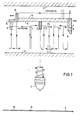
- FIG. 1 represents a control example of a recording element 2 effective on a recording medium 1, whereby, to achieve the movement diagram, a coupling element which is coupled to the recording element 2 and which is shown largely in FIG. 1 in cross section drawn arm 3 suitable stops 4, 5, 6, 7, which also serve the arm 3 as guideways, and spring-mounted, movable in the arrow directions shown locking members 8 and 9 are assigned.
- the recording member 2 In the in FIG. 1 shown position of the arm 3, and thus the recording member 2 is in a first guiding state, which is characterized in that the arm 3 and the recording member 2 by definition "move forward" in the direction of the arrow and at the same time an actuating torque is effective, this causes the arm 3 to bear against the guideway 5 and the recording member to be lifted from the recording medium 1.
- a recording 10 can be made immediately, which in point I of the movement diagram is programmed by reversing the direction of rotation of the drive motor can be interrupted, ie the arm 3 and thus the recording element 2 are returned to the first guide state, in which the arm 3, starting from point K, first strikes the table-like locking member 8 and on this and on the guideway 5 slides along in the "forward direction" until a recording cycle is triggered again at point L at which, for example, creates a record in the form of a line 11.
- FIG. 2 drawn embodiment of a recording arrangement, with which the movement sequence described can be realized, has been chosen for clarity because of a partial exploded view of only the components essential to the invention.
- This shows a link body 13 inserted in a frame 12, the walls 14, 15 and 16 of which represent the stops limiting the pivoting movements of the arm 3 engaging in the link body 13 and formed on an actuating element 17, the respective stop or wall surfaces being the ones described Arm 3 associated guideways 4, 5, 6 and 7 form.
- the locking members 8 and 9 cooperating with the guideways 5 and 6 protrude through suitable openings 19 and 20 formed in the rear wall 18 of the link body 13 into the link body 13 and are on axles fixed in the frame 12, one of which - 21 - is shown - rotatably mounted.
- a spring 22 acting on both locking members 8 and 9 provides the frictional connection between the locking members 8 and 9 and the wall 16 and thus the guideways 5 and 6 of the link body 13.
- the frame 12 which is mounted on a plate 23 fixed to the housing, there is also a suitable manner by inserting it into the side walls of the frame 12, which are not described in more detail, or into the bearing bore 24 formed there and the slotted bearing point 25, which is assigned a bearing bush 25 ' is preferably mounted on a multi-speed threaded spindle 26, the driving gear 27 of which is preferably formed in one piece with the threaded spindle 26 is in geared connection with a pinion 30 attached to the shaft 28 of a stepping motor 29 flanged to the frame 12 and serving as a drive motor.
- the adjusting element 17 which is designed as a traveling nut, is in gear engagement with the threaded spindle 26, ie the adjusting element 17 is actuated by means of a screw gear.
- the adjusting element 17 is provided on one side with a slot 32 which, together with an adjusting screw 34 which is operatively connected to a compression spring 33, permits the setting of an effective friction which enables the pivoting movements of the adjusting element 17 between the threaded spindle 26 and the adjusting element 17.
- the adjusting element 17 can also be produced, for example, as two individual components that can be joined together and connected with the adjusting screw 34.
- Mutually cooperating stops one of which - 35 - is formed directly on the threaded spindle 26 or on its driving gear 27, another - 36 - is fastened on the threaded spindle 26 in the form of a stop disk, as well as associated stops formed on the actuating element 17, of one of which - 37 - is visible, serve the actuating element 17 as end stops in order to avoid it becoming stuck in the limit positions.
- the arm 3 cooperating with the link body 13 is formed on the adjusting element 17.
- a lever 38, which is also formed on the actuating element 17, serves as a driver by removing the carriage 42 from the carriage 42, which is mounted in a bearing bracket 39, which in turn is mounted on a carriage 42 which is displaceably mounted on two stationary guide rods 40 and 41. 2 only shows a cross bar - grips around shaft 43 of recording element 2, which is guided perpendicular to recording medium 1, in a fork-shaped manner.
- the recording member 2 Via a collar 44 fastened to the shaft 43, on which a cutting edge (not specified in more detail) is formed in order to achieve linear contact with the lever 38 the recording member 2 can be raised from the recording medium 1 by pivoting the actuating element 17, while the lowering of the recording member 2 onto the recording medium 1 takes place by means of a bracket 45 which is also connected to the lever 38 via a cutting edge and is displaceably mounted on the shaft 43.
- the bracket 45 is telescopically operatively connected to the recording element 2 via a compression spring 46 which is supported on the bracket 45 and is arranged on the shaft 43 and provides the typing force.
- FIG. 2 shows a section of a recording medium 1, in this case a chart, shows, for example, a bar chart 47 with the same width in a first track, line markings 48 in a second track, a stepped bar chart 49 in a third track, and a zigzag-shaped line chart in a fourth track 5 0 , which can be formed by individual line elements attached to one another or by a row of dots, and in a fifth track, in turn, a bar chart 51 graded according to the program.
- the free space 52 between a printed time scale 53 that is customary in such recording media and the recording tracks mentioned serves, for example in the application case, tachograph recording speed diagrams by means of a further recording element, which is not shown as not essential to the invention. It is of course possible, provided that the programming is appropriate, to record a time scale or time markings 54 in a further track using the recording arrangement according to the invention or to add it directly to, for example, the bar chart 51.
- the recording element 2 is coupled to the lever 38, for example by means of a ball joint, or is arranged directly, ie rigidly, on the actuating element 17 can be net. It is also conceivable to provide a fiber pen or a similar recording medium as the recording element.
- the required torque or actuating torque requires a considerable friction torque that is effective in the gear connection between the threaded spindle 26 and the actuating element 17 and that has to be overcome in the axial movement of the actuating element 17, the exemplary embodiment described according to FIG. 2 highly susceptible to wear, especially since, apart from the fact that a frictional moment formed by thread flanks rubbing against one another has only a limited continuity, in this case the frictional moment is formed on relatively small friction radii.
- FIGS. 3 to 14 The preferred embodiment shown in FIG. 3 - functionally identical components are designated in FIGS. 3 to 14 the same as in FIG. 2 - takes this requirement into account by using a screw mechanism for the movement of the recording element 2 transversely to the recording medium 1 and thus making use of its advantages, but the actuating torque for raising and lowering the recording element 2 perpendicular to the recording medium 1 is generated outside the screw transmission .
- the screw gear can be designed with a suitable pair of materials, for example plastic, and a suitable thread shape, for example a trapezoidal thread, in a special way with low friction and therefore low wear, i.e.
- a friction clutch with a disk-shaped driver 56 which is rotatably mounted on a cylindrical shoulder 55 of the threaded spindle 26 of the screw transmission and which, under the action of a disk spring 57 with an annular collar 58, preferably with the interposition of a disk 59 is supported on the one end face, not designated in more detail, of the gear wheel 27 which forms a part with the threaded spindle 26.
- the wear of the arrangement providing the actuating torque is also negligible.
- the measures taken also have an advantageous effect on the torque requirement of the driving stepping motor 29, which is understandably to be minimized as far as possible.
- the drive torque to be applied by the stepper motor 29 is apart from friction losses in the transmission connection, at least through the recording torque to be overcome and the actuating torque generated by the friction clutch, with which for safety reasons at least 2 to 2.5 times that given by the compression spring 46 Recording enabling tracking power must be achievable.
- the friction clutch for example can be replaced by a toothed segment which is arranged in a suitable manner and in each case when the direction of rotation is reversed and disengages from the drive connection between the stepping motor 29 and the actuating element 17.
- stops 66 and 67 formed on the driver 56 are provided on the one hand, which cooperate with a fixed stop 68, with which the two first guide states can be achieved, and on the other hand the carriage 42 carrying the recording element 2 is one of these locking carriage 69 carried in parallel is assigned, which also cooperates with a fixed stop 7o and which, as will be explained in more detail below, allows the third guide state to be realized.
- FIG. 3 and 4 the FIG. 3 shows a bottom view that the carriage 42, which is displaceably mounted on the guide rods 4o and 41 which are arranged fixed to the housing, is directly operatively connected to the actuating element 17 and thus its entrainment is effected transversely to the recording medium 1 by an arm 71 formed on the carriage 42 (see also FIG 6) or its fork-shaped free end engages the collar 64 of the control element 17.
- a groove-pin connection is also conceivable, the groove having to be arranged in the adjusting element 17.
- a bracket or pocket 72 formed on the carriage 42 is used to fasten a holder 73 which carries the recording element 2 and on which a bearing sleeve 74 which serves to guide the shaft 43 of the recording element 2 is arranged.
- a socket 75 is fastened on the shaft 43, which serves to receive the pressure spring 46 which provides the bearing force of the recording element 2 on the recording medium 1 and is supported at one end on a plate-shaped support 77 which is formed on a slide 76.
- the slide 76 serving as a toothed rack, is in gear engagement with a toothing 79 provided on the actuating element 17 and engages with a tongue 8o through an opening 81 formed in the slide 42. Furthermore, the slide 76, on which a lug 82 is formed, is guided on the adjusting element 17 by two cheeks 83 and 84 encompassing the adjusting element 17 and is supported on the end face by ribs 85 and 86 formed on the slide 42 and by the collar 64.
- the aforementioned lug 82 formed on the slide 76 serves, on the one hand, by engaging between two webs 87 and 88 formed on the bushing 75, for the recording element 2 as a means of preventing rotation, on the other hand, the lug 82, if this - starting from the one shown in FIG. 4 shown guide state - when the direction of rotation is reversed and thus when the slide 76 is adjusted after a certain idling required for the resilience of the recording element 2 resting on the recording medium 1, strikes the flange surface 89 of the socket 75, the recording element 2 is raised from the recording medium 1.
- the locking slide 69 which, as shown, is mounted riding on the guide rod 40, is carried along by the slide 42 due to a certain friction between the two slides 42 and 69.
- Stop arms 9o and 91 formed on the blocking slide 69 cooperate with the fixed stop 7o.
- the locking slide 69 is one with two cams 92 and 93, which cooperate with a pin 95 fastened in the slide 42 ken, provided bracket 94 molded resiliently.
- a finger 96 is formed on the blocking slide 69, which extends through an opening 97 located in the slide 42, which is tolerated relatively closely.
- a gear pair 99, 100 is switched on and that the drive of the stepping motor 29 can also be used, for example by using a worm 101 coupled to the threaded spindle 26 and a worm wheel lo2 a further recording element, not shown, can be actuated.
- the shaft 62 of the screw transmission is fixed in bearings 103 and 104 and is under the action of a fixedly clamped leaf spring 105 with a certain preload, which, as already in connection with the embodiment according to FIG. 2 has been described, which serves to compensate for the relatively strong axial thrust, in particular when recording.
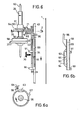
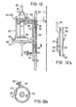
- FIG. 6 to 14 which represent characteristic functional positions of the recording arrangement according to the invention, are explained.
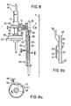
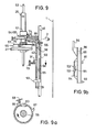
- FIG. 6 to 14 which are essentially as side views of FIG. 3, each show a view of the position of the driver 56 with respect to the fixed stop 68 and a view of the position of the locking slide 69 with respect to the assigned pin 95 arranged on the carriage 42.
- the tip of the recording element 2 is shown schematically.
- the functional positions in which the guide web 63 would have to be shown in broken lines it has not been shown.
- the arrows assigned to the carriage 42 and the threaded spindle 26 are intended to indicate the direction of movement of these components, while the arrow assigned to the driver 56 in each case denotes the direction of action of the torque acting on the driver 56. It should also be noted that in the selected representation, the threaded spindle 26 is provided with a thread rising to the left.
- FIG. 6 now refer to a functional position of the recording arrangement, which at an arbitrary, known.
- First guide state corresponding position of the registration field can be given with respect to the carriage 42 and thus the A ufobossorgan 2 ie, "advanced".
- the direction of rotation of the stepper motor 29 and thus of the threaded spindle 26 is such that an actuating torque in the sense of lifting the recording element 2 from the recording medium 1 is effective on the slide 76 via the adjusting element 17 - the driver 56 rests with its stop 66 on the stationary stop 68 is.
- the recording arrangement As shown in FIG. 8 already show a functional position corresponding to the first guidance state, i.e. the stop 66 of the driver 56 rests on the fixed stop 68, the recording member 2 is raised from the recording medium 1 and the carriage 42 is subsequently moved again in the "forward direction".
- the recording cycle controlled by the predetermined program in which the number of steps of the stepping motor for the respective movement section of the recording arrangement and the commands for reversing the direction of rotation remains, as shown in FIG. 7b and 8b show the position of the locking slide 69 with respect to the slide 42 unchanged. This changes when the stop arm 91 of the locking slide 69 strikes the stationary stop 70 when the slide 42 moves further forward, but the slide 42 is moved further in the same direction.
- FIG. 9 A corresponding functional position is shown in FIG. 9 shown. These show that the carriage-fixed pin 95 has moved away from the cams 93 formed on the blocking carriage 69 and the finger 96 formed on the blocking carriage 69 has advanced against the tongue 80 of the slide 76. Since the recording takes place during "backward movement" of the recording arrangement, a recording cycle can still be controlled in this functional position.
- FIG. 11 show the recording arrangement in a functional position, in which the functional position according to FIG. 10, the direction of rotation has been reversed and a "backward movement" of the carriage 42 has been initiated.
- the tongue 8o is placed on the finger 96 of the locking slide 69 under the action of the torque exerted by the driver 56 and thus, which corresponds to the third guide state, prevents the recording member 2 from being lowered onto the recording medium 1.
- the wedge-shaped end of the tongue 8o can be assigned a corresponding oblique surface formed on the finger 96.
- the cams 92 and 93 in The first and second guide states serve to prevent the locking slide 69 from either sliding into the movement path of the tongue 8o in the event of insufficient friction with the slide 42 or from vibrations, or the finger 96 sliding out of its guide (opening 97) in the slide 42.
Landscapes
- Physics & Mathematics (AREA)
- General Physics & Mathematics (AREA)
- Character Spaces And Line Spaces In Printers (AREA)
- Recording Measured Values (AREA)
- Moving Of Heads (AREA)
Applications Claiming Priority (2)
| Application Number | Priority Date | Filing Date | Title |
|---|---|---|---|
| DE19823232980 DE3232980A1 (de) | 1982-09-04 | 1982-09-04 | Verfahren zum steuern eines aufzeichnungsorgans |
| DE3232980 | 1982-09-04 |
Publications (2)
| Publication Number | Publication Date |
|---|---|
| EP0102595A1 true EP0102595A1 (fr) | 1984-03-14 |
| EP0102595B1 EP0102595B1 (fr) | 1987-05-06 |
Family
ID=6172516
Family Applications (1)
| Application Number | Title | Priority Date | Filing Date |
|---|---|---|---|
| EP83108404A Expired EP0102595B1 (fr) | 1982-09-04 | 1983-08-26 | Procédé pour contrôler un élément d'enregistrement |
Country Status (3)
| Country | Link |
|---|---|
| EP (1) | EP0102595B1 (fr) |
| JP (1) | JPS5965718A (fr) |
| DE (2) | DE3232980A1 (fr) |
Cited By (3)
| Publication number | Priority date | Publication date | Assignee | Title |
|---|---|---|---|---|
| FR2658937A1 (fr) * | 1990-02-28 | 1991-08-30 | Jaeger | Dispositif inscripteur pour enregistreurs de route de vehicule, pouvant entrer en action automatiquement des que le vehicule est en marche et aussi lorsque le vehicule est a l'arret. |
| EP0676728A3 (fr) * | 1994-04-08 | 1997-02-19 | Mannesmann Kienzle Gmbh | Dispositif pour la caractérisation alphanumérique de disques à diagramme utilisés dans un tachygraphe. |
| KR101111266B1 (ko) * | 2009-06-29 | 2012-03-14 | 유한콘크리트산업 주식회사 | 블록의 표면 처리장치 |
Families Citing this family (1)
| Publication number | Priority date | Publication date | Assignee | Title |
|---|---|---|---|---|
| DE3408064A1 (de) * | 1982-09-04 | 1985-09-19 | Kienzle Apparate Gmbh, 7730 Villingen-Schwenningen | Anordnung zum steuern eines aufzeichnungsorgans |
Citations (3)
| Publication number | Priority date | Publication date | Assignee | Title |
|---|---|---|---|---|
| DE1276351B (de) * | 1961-11-07 | 1968-08-29 | Leeds & Northrup Co | Registriergeraet |
| DE2231545A1 (de) * | 1972-06-28 | 1974-01-10 | Kienzle Apparate Gmbh | Registriereinrichtung fuer fahrtschreiber |
| DE2335340B2 (de) * | 1972-07-12 | 1977-05-05 | Furuno Electric Co., Ltd., Nishinomiya, Hyogo (Japan) | Digitalgesteuerte aufzeichnungsvorrichtung |
-
1982
- 1982-09-04 DE DE19823232980 patent/DE3232980A1/de not_active Withdrawn
-
1983
- 1983-08-26 DE DE8383108404T patent/DE3371415D1/de not_active Expired
- 1983-08-26 EP EP83108404A patent/EP0102595B1/fr not_active Expired
- 1983-09-05 JP JP58162098A patent/JPS5965718A/ja active Granted
Patent Citations (3)
| Publication number | Priority date | Publication date | Assignee | Title |
|---|---|---|---|---|
| DE1276351B (de) * | 1961-11-07 | 1968-08-29 | Leeds & Northrup Co | Registriergeraet |
| DE2231545A1 (de) * | 1972-06-28 | 1974-01-10 | Kienzle Apparate Gmbh | Registriereinrichtung fuer fahrtschreiber |
| DE2335340B2 (de) * | 1972-07-12 | 1977-05-05 | Furuno Electric Co., Ltd., Nishinomiya, Hyogo (Japan) | Digitalgesteuerte aufzeichnungsvorrichtung |
Cited By (4)
| Publication number | Priority date | Publication date | Assignee | Title |
|---|---|---|---|---|
| FR2658937A1 (fr) * | 1990-02-28 | 1991-08-30 | Jaeger | Dispositif inscripteur pour enregistreurs de route de vehicule, pouvant entrer en action automatiquement des que le vehicule est en marche et aussi lorsque le vehicule est a l'arret. |
| EP0445031A1 (fr) * | 1990-02-28 | 1991-09-04 | Jaeger | Dispositif inscripteur pour enregistreurs de route de véhicule, pouvant entrer en action automatiquement dès que le véhicule est en marche et aussi lorsque le véhicule est à l'arrêt |
| EP0676728A3 (fr) * | 1994-04-08 | 1997-02-19 | Mannesmann Kienzle Gmbh | Dispositif pour la caractérisation alphanumérique de disques à diagramme utilisés dans un tachygraphe. |
| KR101111266B1 (ko) * | 2009-06-29 | 2012-03-14 | 유한콘크리트산업 주식회사 | 블록의 표면 처리장치 |
Also Published As
| Publication number | Publication date |
|---|---|
| JPS5965718A (ja) | 1984-04-14 |
| DE3232980A1 (de) | 1984-03-08 |
| DE3371415D1 (en) | 1987-06-11 |
| EP0102595B1 (fr) | 1987-05-06 |
| JPH0369051B2 (fr) | 1991-10-30 |
Similar Documents
| Publication | Publication Date | Title |
|---|---|---|
| DE2013836A1 (de) | Werkzeugmaschine | |
| DE2455142A1 (de) | Modularer servospurschreiber mit linearer lageeinstellung | |
| DE3008735C2 (de) | Vorrichtung zur Verstellung der Fadenspannung für mehrnadelige Stickautomaten | |
| DE3528120C1 (de) | Kraftbetaetigtes Spannfutter | |
| DE2745396B1 (de) | Mehrkopfstickmaschine | |
| EP0102595B1 (fr) | Procédé pour contrôler un élément d'enregistrement | |
| DE2159201C3 (de) | Vorrichtung zur Führung und Bewegung eines Lesekopfes | |
| DE4205777C2 (de) | Drucker für die Verarbeitung von Aufzeichnungsträgern unterschiedlicher Dicke in Form von Einzelblättern und Endlosbahnen | |
| EP0800151B1 (fr) | Liaison d'entraínement pour un dispositif d'enregistrement de tachygraphe | |
| EP1127700B1 (fr) | Dispositif et méthode d'impression avec guidage mobile pour tête d'impression | |
| DE3511316A1 (de) | Thermodrucker | |
| DE69715683T2 (de) | Linearantriebsvorrichtung | |
| EP0064668B1 (fr) | Pivot pour mécanisme d'impression | |
| EP0138268B1 (fr) | Mécanisme de commande de l'entraînement d'un appareil à cassette à bande magnétique | |
| DE2546921A1 (de) | Steuervorrichtung fuer einen tonarm eines plattenspielers, insbesondere automatischen plattenspielers | |
| DE2145843C3 (de) | Druckeinrichtung | |
| DE919789C (de) | Papierwageneinstellvorrichtung fuer Buchungs- und aehnliche Maschinen | |
| DE69314432T2 (de) | Markierapparat | |
| EP0769439B1 (fr) | Commande d'aiguillage à course réglable | |
| EP0394863B1 (fr) | Dispositif pour le positionnement de charriots mobiles p. ex. de machine-outil | |
| DE3408064A1 (de) | Anordnung zum steuern eines aufzeichnungsorgans | |
| DE4024921A1 (de) | Flachstrickmaschine | |
| DE246576C (fr) | ||
| DE2618035A1 (de) | Antriebsvorrichtung fuer drucker | |
| DE2057923C (de) | Seriendrucker |
Legal Events
| Date | Code | Title | Description |
|---|---|---|---|
| PUAI | Public reference made under article 153(3) epc to a published international application that has entered the european phase |
Free format text: ORIGINAL CODE: 0009012 |
|
| AK | Designated contracting states |
Designated state(s): DE FR GB IT |
|
| 17P | Request for examination filed |
Effective date: 19840607 |
|
| RAP1 | Party data changed (applicant data changed or rights of an application transferred) |
Owner name: MANNESMANN KIENZLE GMBH |
|
| 17Q | First examination report despatched |
Effective date: 19860509 |
|
| GRAA | (expected) grant |
Free format text: ORIGINAL CODE: 0009210 |
|
| AK | Designated contracting states |
Kind code of ref document: B1 Designated state(s): DE FR GB IT |
|
| ITF | It: translation for a ep patent filed | ||
| REF | Corresponds to: |
Ref document number: 3371415 Country of ref document: DE Date of ref document: 19870611 |
|
| ET | Fr: translation filed | ||
| PLBE | No opposition filed within time limit |
Free format text: ORIGINAL CODE: 0009261 |
|
| STAA | Information on the status of an ep patent application or granted ep patent |
Free format text: STATUS: NO OPPOSITION FILED WITHIN TIME LIMIT |
|
| 26N | No opposition filed | ||
| ITTA | It: last paid annual fee | ||
| PGFP | Annual fee paid to national office [announced via postgrant information from national office to epo] |
Ref country code: FR Payment date: 19950714 Year of fee payment: 13 |
|
| PG25 | Lapsed in a contracting state [announced via postgrant information from national office to epo] |
Ref country code: FR Effective date: 19970430 |
|
| REG | Reference to a national code |
Ref country code: FR Ref legal event code: ST |
|
| PGFP | Annual fee paid to national office [announced via postgrant information from national office to epo] |
Ref country code: GB Payment date: 19970716 Year of fee payment: 15 |
|
| PG25 | Lapsed in a contracting state [announced via postgrant information from national office to epo] |
Ref country code: GB Free format text: LAPSE BECAUSE OF NON-PAYMENT OF DUE FEES Effective date: 19980826 |
|
| GBPC | Gb: european patent ceased through non-payment of renewal fee |
Effective date: 19980826 |
|
| PGFP | Annual fee paid to national office [announced via postgrant information from national office to epo] |
Ref country code: DE Payment date: 20000925 Year of fee payment: 18 |
|
| PG25 | Lapsed in a contracting state [announced via postgrant information from national office to epo] |
Ref country code: DE Free format text: LAPSE BECAUSE OF NON-PAYMENT OF DUE FEES Effective date: 20020501 |