EP0102633A1 - Fusée pour projectiles giratoires - Google Patents
Fusée pour projectiles giratoires Download PDFInfo
- Publication number
- EP0102633A1 EP0102633A1 EP83108696A EP83108696A EP0102633A1 EP 0102633 A1 EP0102633 A1 EP 0102633A1 EP 83108696 A EP83108696 A EP 83108696A EP 83108696 A EP83108696 A EP 83108696A EP 0102633 A1 EP0102633 A1 EP 0102633A1
- Authority
- EP
- European Patent Office
- Prior art keywords
- axis
- holder
- fuze
- rearward
- detonator
- Prior art date
- Legal status (The legal status is an assumption and is not a legal conclusion. Google has not performed a legal analysis and makes no representation as to the accuracy of the status listed.)
- Withdrawn
Links
- 238000010304 firing Methods 0.000 claims abstract description 17
- 230000033001 locomotion Effects 0.000 claims abstract description 6
- 230000007246 mechanism Effects 0.000 description 8
- 239000002360 explosive Substances 0.000 description 6
- 238000009304 pastoral farming Methods 0.000 description 6
- 230000001133 acceleration Effects 0.000 description 1
- 230000006835 compression Effects 0.000 description 1
- 238000007906 compression Methods 0.000 description 1
- 230000007423 decrease Effects 0.000 description 1
- 230000002093 peripheral effect Effects 0.000 description 1
- 230000000452 restraining effect Effects 0.000 description 1
- 230000035945 sensitivity Effects 0.000 description 1
Images
Classifications
-
- F—MECHANICAL ENGINEERING; LIGHTING; HEATING; WEAPONS; BLASTING
- F42—AMMUNITION; BLASTING
- F42C—AMMUNITION FUZES; ARMING OR SAFETY MEANS THEREFOR
- F42C15/00—Arming-means in fuzes; Safety means for preventing premature detonation of fuzes or charges
- F42C15/18—Arming-means in fuzes; Safety means for preventing premature detonation of fuzes or charges wherein a carrier for an element of the pyrotechnic or explosive train is moved
- F42C15/188—Arming-means in fuzes; Safety means for preventing premature detonation of fuzes or charges wherein a carrier for an element of the pyrotechnic or explosive train is moved using a rotatable carrier
- F42C15/192—Arming-means in fuzes; Safety means for preventing premature detonation of fuzes or charges wherein a carrier for an element of the pyrotechnic or explosive train is moved using a rotatable carrier rotatable in a plane which is parallel to the longitudinal axis of the projectile
- F42C15/196—Arming-means in fuzes; Safety means for preventing premature detonation of fuzes or charges wherein a carrier for an element of the pyrotechnic or explosive train is moved using a rotatable carrier rotatable in a plane which is parallel to the longitudinal axis of the projectile by the action of centrifugal or inertia forces on the carrier body, e.g. the carrier having eccentrically mounted weights or eccentric centre of gravity
-
- F—MECHANICAL ENGINEERING; LIGHTING; HEATING; WEAPONS; BLASTING
- F42—AMMUNITION; BLASTING
- F42C—AMMUNITION FUZES; ARMING OR SAFETY MEANS THEREFOR
- F42C15/00—Arming-means in fuzes; Safety means for preventing premature detonation of fuzes or charges
- F42C15/24—Arming-means in fuzes; Safety means for preventing premature detonation of fuzes or charges wherein the safety or arming action is effected by inertia means
- F42C15/26—Arming-means in fuzes; Safety means for preventing premature detonation of fuzes or charges wherein the safety or arming action is effected by inertia means using centrifugal force
-
- F—MECHANICAL ENGINEERING; LIGHTING; HEATING; WEAPONS; BLASTING
- F42—AMMUNITION; BLASTING
- F42C—AMMUNITION FUZES; ARMING OR SAFETY MEANS THEREFOR
- F42C9/00—Time fuzes; Combined time and percussion or pressure-actuated fuzes; Fuzes for timed self-destruction of ammunition
- F42C9/14—Double fuzes; Multiple fuzes
- F42C9/16—Double fuzes; Multiple fuzes for self-destruction of ammunition
- F42C9/18—Double fuzes; Multiple fuzes for self-destruction of ammunition when the spin rate falls below a predetermined limit, e.g. a spring force being stronger than the locking action of a centrifugally-operated lock
Definitions
- the present invention relates to a fuze for projectiles according to the preamble of claim 1. More particularly the present invention relates to fuzing mechanisms useable in rounds of ammunition in the size range of 20mm to 40mm..
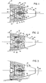
- the inventive mechanism 10 is shown in a projectile including a forward fuze 11 and a rearward casing 12 for a warhead explosive, not shown.
- Fuze 11 includes an ogive 13 and a base 14 containing a lead explosive 15 effective to fire the warhead explosive.
- a firing pin 16 projects rearwardly along the longitudinal axis 17 of the projectile, about which the projectile moves and spins in flight.
- a central chamber 20 is formed in ogive 13 and contains a detonator holder 21 comprising an outer portion 22 cylindrical about axis 17 and movable therealong in chamber 20, and an inner portion 23 cylindrical about a second axis orthogonal to axis 17 and rotatable in portion 22 about said second axis.
- a roller 24 is free to rotate in a groove 25, which extends along the periphery of portion 23 parallel to the second axis, and which is deeper than the diameter of roller 24, and a second groove 26 extends in member 22 parallel to the second axis, for reasons presently to be explained.
- Portion 22 has a first axial opening 27 of small diameter, to pass firing pin 16, and a second, larger axial opening 30.
- Portion 23 has a short radial bore 31 to receive pin 16 in one rotated position, and a cross-bore 32 to receive a detonator 33, bore 32 being in line with openings 27 and 30 in a second rotated position of portion 23.
- a crush cup 34 is positioned so that one end bears against base 14, and the other bears against holder portion 22.
- a plurality of balls 35 spaced about axis 17 are carried in radial holes 36 in portion 22, and an inward peripheral groove or ramp 37 is formed in the wall of chamber 20, rearward of the normal axial location of balls 35.
- a light biasing compression spring 40 best shown in FIGURE 2 may be provided to act between holder 21 and firing pin 16, but is not strong enough to deform cup 34.
- detonator 33 In the normal condition of the fuze shown in FIGURE 1 detonator 33 is completely enclosed within portions 22 and 23 of holder 21, which is held forward against ogive 13 by cup 34, firing pin 16 is received in bore 31, balls 35 are fully within holes 36 and forward of ramp 37.,. and roller 24 is fully in groove 25.
- FIGURE 2 shows the projectile in flight.
- holder 21 By its inertia during acceleration of the projectile at discharge, holder 21 has moved rearward, crushing cup 34, and the spin of the projectile about axis 17 forces balls 35 radially into ramp 37 and holds them there.
- the firing pin mechanism Upon direct impact with a target, the firing pin mechanism is forced into detonator 30, by crushing of fuze 11, sufficiently to initiate the warhead explosive.
- the - invention comprises means including a specially mounted inertial mass for increasing the firing reliability of a projectile upon contact with a target at grazing angles.
Landscapes
- Engineering & Computer Science (AREA)
- General Engineering & Computer Science (AREA)
- Air Bags (AREA)
Applications Claiming Priority (2)
| Application Number | Priority Date | Filing Date | Title |
|---|---|---|---|
| US41510182A | 1982-09-07 | 1982-09-07 | |
| US415101 | 1982-09-07 |
Publications (1)
| Publication Number | Publication Date |
|---|---|
| EP0102633A1 true EP0102633A1 (fr) | 1984-03-14 |
Family
ID=23644388
Family Applications (1)
| Application Number | Title | Priority Date | Filing Date |
|---|---|---|---|
| EP83108696A Withdrawn EP0102633A1 (fr) | 1982-09-07 | 1983-09-03 | Fusée pour projectiles giratoires |
Country Status (1)
| Country | Link |
|---|---|
| EP (1) | EP0102633A1 (fr) |
Citations (3)
| Publication number | Priority date | Publication date | Assignee | Title |
|---|---|---|---|---|
| US3636880A (en) * | 1968-12-13 | 1972-01-25 | Honeywell Inc | Control apparatus |
| US4004521A (en) * | 1976-04-01 | 1977-01-25 | The United States Of America As Represented By The Secretary Of The Army | Projectile fuze |
| US4242963A (en) * | 1978-09-25 | 1981-01-06 | General Electric Company | Delayed arming fuze for a spinning projectile |
-
1983
- 1983-09-03 EP EP83108696A patent/EP0102633A1/fr not_active Withdrawn
Patent Citations (3)
| Publication number | Priority date | Publication date | Assignee | Title |
|---|---|---|---|---|
| US3636880A (en) * | 1968-12-13 | 1972-01-25 | Honeywell Inc | Control apparatus |
| US4004521A (en) * | 1976-04-01 | 1977-01-25 | The United States Of America As Represented By The Secretary Of The Army | Projectile fuze |
| US4242963A (en) * | 1978-09-25 | 1981-01-06 | General Electric Company | Delayed arming fuze for a spinning projectile |
Similar Documents
| Publication | Publication Date | Title |
|---|---|---|
| US9562755B2 (en) | Safe and arm mechanisms and methods for explosive devices | |
| EP1155279B1 (fr) | Fusee percutante a destruction automatique | |
| CA2674650C (fr) | Fusee percutante fonctionnant par autodestruction | |
| US3995557A (en) | Base fuze for a spinning projectile | |
| US6604467B2 (en) | Safety system for a projectile fuse | |
| EP0681157B1 (fr) | Allumeur pour une sous-munition muni d'un dispositif d'autodestruction et d'un allumeur à inertie | |
| KR20110018280A (ko) | 기계적 커맨드 투 아암 신관 | |
| US3636880A (en) | Control apparatus | |
| US6035783A (en) | High performance fuze | |
| CA2326432C (fr) | Systeme de securite pour amorce de projectile | |
| US5670736A (en) | Priming system for the explosive charge of a submunition on board a carrier | |
| US3768415A (en) | Fuze arming device | |
| US7360486B2 (en) | Safety system for the ignition chain of a projectile fuze | |
| US5056434A (en) | Spin integrating safe and arm device for spinning munitions | |
| US7798064B1 (en) | Command and arm fuze assembly having small piston actuator | |
| GB2083175A (en) | Detonator assembly and explosive projectile | |
| US3830159A (en) | Mechanism | |
| HK1030257B (en) | Safety system for a projectile fuse |
Legal Events
| Date | Code | Title | Description |
|---|---|---|---|
| PUAI | Public reference made under article 153(3) epc to a published international application that has entered the european phase |
Free format text: ORIGINAL CODE: 0009012 |
|
| AK | Designated contracting states |
Designated state(s): CH DE FR GB LI SE |
|
| STAA | Information on the status of an ep patent application or granted ep patent |
Free format text: STATUS: THE APPLICATION IS DEEMED TO BE WITHDRAWN |
|
| 18D | Application deemed to be withdrawn |
Effective date: 19841115 |
|
| RIN1 | Information on inventor provided before grant (corrected) |
Inventor name: STROBUSH, VICTOR H. |