EP0102648A2 - Table pour le support de patients - Google Patents
Table pour le support de patients Download PDFInfo
- Publication number
- EP0102648A2 EP0102648A2 EP83108824A EP83108824A EP0102648A2 EP 0102648 A2 EP0102648 A2 EP 0102648A2 EP 83108824 A EP83108824 A EP 83108824A EP 83108824 A EP83108824 A EP 83108824A EP 0102648 A2 EP0102648 A2 EP 0102648A2
- Authority
- EP
- European Patent Office
- Prior art keywords
- plate
- longitudinal
- leg
- spars
- cross
- Prior art date
- Legal status (The legal status is an assumption and is not a legal conclusion. Google has not performed a legal analysis and makes no representation as to the accuracy of the status listed.)
- Granted
Links
- 229910052751 metal Inorganic materials 0.000 claims description 14
- 239000002184 metal Substances 0.000 claims description 14
- 229920003023 plastic Polymers 0.000 claims description 11
- 239000004033 plastic Substances 0.000 claims description 11
- 238000004026 adhesive bonding Methods 0.000 claims description 5
- 238000006073 displacement reaction Methods 0.000 claims description 5
- 239000002984 plastic foam Substances 0.000 claims 1
- 239000012530 fluid Substances 0.000 description 7
- 238000005452 bending Methods 0.000 description 5
- 239000000463 material Substances 0.000 description 4
- 230000006835 compression Effects 0.000 description 3
- 238000007906 compression Methods 0.000 description 3
- 230000006378 damage Effects 0.000 description 3
- 238000003780 insertion Methods 0.000 description 3
- 230000037431 insertion Effects 0.000 description 3
- 208000027418 Wounds and injury Diseases 0.000 description 2
- 229910052782 aluminium Inorganic materials 0.000 description 2
- XAGFODPZIPBFFR-UHFFFAOYSA-N aluminium Chemical compound [Al] XAGFODPZIPBFFR-UHFFFAOYSA-N 0.000 description 2
- 238000010276 construction Methods 0.000 description 2
- 230000000881 depressing effect Effects 0.000 description 2
- 230000000994 depressogenic effect Effects 0.000 description 2
- 208000014674 injury Diseases 0.000 description 2
- 230000000149 penetrating effect Effects 0.000 description 2
- -1 Polyethylene Polymers 0.000 description 1
- 239000004698 Polyethylene Substances 0.000 description 1
- 229920005830 Polyurethane Foam Polymers 0.000 description 1
- 238000010521 absorption reaction Methods 0.000 description 1
- 230000000712 assembly Effects 0.000 description 1
- 238000000429 assembly Methods 0.000 description 1
- 239000008280 blood Substances 0.000 description 1
- 210000004369 blood Anatomy 0.000 description 1
- 238000004140 cleaning Methods 0.000 description 1
- 238000011109 contamination Methods 0.000 description 1
- 230000000694 effects Effects 0.000 description 1
- 230000002349 favourable effect Effects 0.000 description 1
- 238000002594 fluoroscopy Methods 0.000 description 1
- 210000003141 lower extremity Anatomy 0.000 description 1
- 210000000056 organ Anatomy 0.000 description 1
- 229920000573 polyethylene Polymers 0.000 description 1
- 239000011496 polyurethane foam Substances 0.000 description 1
- 230000000284 resting effect Effects 0.000 description 1
- 239000007787 solid Substances 0.000 description 1
- 230000007704 transition Effects 0.000 description 1
Images


Classifications
-
- A—HUMAN NECESSITIES
- A61—MEDICAL OR VETERINARY SCIENCE; HYGIENE
- A61G—TRANSPORT, PERSONAL CONVEYANCES, OR ACCOMMODATION SPECIALLY ADAPTED FOR PATIENTS OR DISABLED PERSONS; OPERATING TABLES OR CHAIRS; CHAIRS FOR DENTISTRY; FUNERAL DEVICES
- A61G7/00—Beds specially adapted for nursing; Devices for lifting patients or disabled persons
- A61G7/10—Devices for lifting patients or disabled persons, e.g. special adaptations of hoists thereto
- A61G7/104—Devices carried or supported by
- A61G7/1046—Mobile bases, e.g. having wheels
-
- A—HUMAN NECESSITIES
- A61—MEDICAL OR VETERINARY SCIENCE; HYGIENE
- A61G—TRANSPORT, PERSONAL CONVEYANCES, OR ACCOMMODATION SPECIALLY ADAPTED FOR PATIENTS OR DISABLED PERSONS; OPERATING TABLES OR CHAIRS; CHAIRS FOR DENTISTRY; FUNERAL DEVICES
- A61G1/00—Stretchers
- A61G1/02—Stretchers with wheels
- A61G1/0206—Stretchers with wheels characterised by the number of supporting wheels if stretcher is extended
- A61G1/0212—2 pairs having wheels within a pair on the same position in longitudinal direction, e.g. on the same axis
-
- A—HUMAN NECESSITIES
- A61—MEDICAL OR VETERINARY SCIENCE; HYGIENE
- A61G—TRANSPORT, PERSONAL CONVEYANCES, OR ACCOMMODATION SPECIALLY ADAPTED FOR PATIENTS OR DISABLED PERSONS; OPERATING TABLES OR CHAIRS; CHAIRS FOR DENTISTRY; FUNERAL DEVICES
- A61G1/00—Stretchers
- A61G1/02—Stretchers with wheels
- A61G1/0237—Stretchers with wheels having at least one swivelling wheel, e.g. castors
- A61G1/0243—Stretchers with wheels having at least one swivelling wheel, e.g. castors with lockable swivel action, e.g. fixing castor in certain direction
-
- A—HUMAN NECESSITIES
- A61—MEDICAL OR VETERINARY SCIENCE; HYGIENE
- A61G—TRANSPORT, PERSONAL CONVEYANCES, OR ACCOMMODATION SPECIALLY ADAPTED FOR PATIENTS OR DISABLED PERSONS; OPERATING TABLES OR CHAIRS; CHAIRS FOR DENTISTRY; FUNERAL DEVICES
- A61G1/00—Stretchers
- A61G1/02—Stretchers with wheels
- A61G1/0293—Stretchers with wheels stretcher supports with wheels, e.g. used for stretchers without wheels
-
- A—HUMAN NECESSITIES
- A61—MEDICAL OR VETERINARY SCIENCE; HYGIENE
- A61G—TRANSPORT, PERSONAL CONVEYANCES, OR ACCOMMODATION SPECIALLY ADAPTED FOR PATIENTS OR DISABLED PERSONS; OPERATING TABLES OR CHAIRS; CHAIRS FOR DENTISTRY; FUNERAL DEVICES
- A61G7/00—Beds specially adapted for nursing; Devices for lifting patients or disabled persons
- A61G7/10—Devices for lifting patients or disabled persons, e.g. special adaptations of hoists thereto
-
- A—HUMAN NECESSITIES
- A61—MEDICAL OR VETERINARY SCIENCE; HYGIENE
- A61B—DIAGNOSIS; SURGERY; IDENTIFICATION
- A61B17/00—Surgical instruments, devices or methods
- A61B2017/00831—Material properties
- A61B2017/00902—Material properties transparent or translucent
-
- A—HUMAN NECESSITIES
- A61—MEDICAL OR VETERINARY SCIENCE; HYGIENE
- A61G—TRANSPORT, PERSONAL CONVEYANCES, OR ACCOMMODATION SPECIALLY ADAPTED FOR PATIENTS OR DISABLED PERSONS; OPERATING TABLES OR CHAIRS; CHAIRS FOR DENTISTRY; FUNERAL DEVICES
- A61G2200/00—Information related to the kind of patient or his position
- A61G2200/30—Specific positions of the patient
- A61G2200/32—Specific positions of the patient lying
Definitions
- the invention relates to a table for positioning patients according to the preamble of claim 1.
- the plate arrangement is firmly connected to the frame. This can make it difficult to lift or lift a patient off the panel assembly, and if the panel assembly needs to be cleaned, the entire table must be cleaned, even if the rack is not contaminated.
- the invention has for its object to develop a table of the type mentioned in such a way that it is easy to handle, in particular when transferring patients to or from the plate arrangement, as well as when cleaning is required.
- the object is achieved according to the invention in a table for the storage of patients of the type mentioned by the features specified in the characterizing part of claim 1.
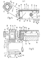
- the table used for storing patients comprises a frame 10 (FIGS. 1, 11, 12) and a plate arrangement 12 (FIGS. 1, 2) detachably held thereon.
- the frame 10 has two horizontal support spars 14 running near its end faces, transverse to its longitudinal extent, which are each formed by a tube 16 with a circular cross section and two cheeks 18 attached to the ends thereof and projecting upward beyond the tube 16.
- the latter holder. the Plattenanordnunq 12 on their support blocks 20, 22 against lateral displacement relative to the frame 10.
- the frame 10 is designed to be movable by means of four trailing rollers 24.
- the trailing rollers 24 are either blocked against rotation and pivoting about the vertical axis or only blocked against pivoting, but rotatable or freely rotatable and pivotable in a third position.
- the plate assembly 12 is very stable due to its construction described below and in particular torsionally rigid, so that it can also be used in a state separated from the frame 10 for all types of use. It comprises two mirror-symmetrical with respect to the longitudinal axis, due to their Profiling still to be described, particularly rigid longitudinal spars 28, which form their long sides, and two plates held between the longitudinal spars 28, namely a leg plate 30 and a head plate 32. The latter is pivotally articulated to the longitudinal spars 28 near the leg plate 30, so that it can be pivoted upwards from a flush with the leg plate, when the plate arrangement 12 is held horizontally on the frame as in FIG.
- the leg plate 30 serves to support the legs and also the lower body of a patient, while the head plate 32 serves to support the upper body and head.
- the maximum pivoting angle of the head plate 32 should expediently be 65 ° in order to be able to largely straighten the patient with his upper body.
- the leg plate 30 and the head plate 32 can be X-rayed from q e formed.
- the plates 30, 32 should be as thin as possible, while on the other hand good strength is desirable so that the plates 30, 32 are not under the weight of a patient bend and thus contribute to the torsional rigidity of the plate assembly 12. It has been found that such properties of the plates 30, 32, in deviation from known plates consisting of a plastic base plate and upholstery, can be achieved in that the plates 30, 32, as can be seen, for example, in FIGS there are relatively thick plastic layers 34, 36 and at least one flat metal layer 38, 40 or 42, 44 connected to it, thin relative to the plastic layer 34, 36.
- the plastic layer 34 is provided on both sides with such metal layers 38, 40 or 42 , 44. These can be glued to the plastic layer 34 or 36.
- Polyethylene has proven to be a suitable material for the plastic layer 34, 36.
- the metal layers 38, 40; 42, 44 suitably consist of aluminum as in the exemplary embodiment. This can be a hard, but not brittle, anodized aluminum on the outside.
- this layer structure of the plates 30, 32 it is sufficient if they each have a total thickness of 4 mm, which in the exemplary embodiment is composed of a thickness of 3 mm of the plastic layers 36, 38 and thicknesses of 0.5 mm of the metal layers 38, 40 and 42, 44.
- the leg plate 30 and the head plate 32 should have the same thicknesses and the same layer structure, so that they have the same absorption characteristics when fluoroscopic.
- the longitudinal bars 28 are connected to the end faces of the plate arrangement by means of transverse bars 46, which with the longitudinal bars 28 form a rectangular, torsionally rigid frame form.
- the cross bars 46 have a U-shaped shape in plan view with a straight handle section 48 running perpendicular to the cross bars 28 and two legs 50 bent thereon and bent to the longitudinal bars 28 and fastened at the ends thereof.
- the handle section runs from the respectively adjacent end face of FIG Leg plate 30 or the head plate 22 spaced such that it can be easily gripped by an operator.
- the legs 50 have a curve which is bent upwards relative to the plane of the longitudinal bars 2b, so that the grip section 48 with more than that Half of its height above the top of the longitudinal spars 28 lies.
- the handle section 48 is arranged such that its one diagonal 52, which is horizontal in FIG. 4, runs parallel to the plane of the longitudinal bars 28.
- an upper side 54 of the grip section 48 lying toward the leg plate 30 or towards the head plate 32 has a gentle inclination with respect to the patient.
- the handle portion 48 is strongly rounded at the corners of its cross section.
- the entire cross member in each case consists of a rectangular, in the exemplary embodiment square in the handle section 48, metallic tube 56 and a sheath 58 made of polyurethane foam.
- the legs 50 continue in pins 60 (FIG. 5) which are inserted into the ends of the hollow longitudinal spars 28 and fastened therein.
- the casing 58 extends with the release of the pins 60 over both the handle portion 48 and the legs 50 and closes externally aligned with the top, outside and bottom of an at least approximately rectangular cross-sectional area 62 (FIGS. 3, 5) at the ends of the longitudinal spars 28.
- the already mentioned, approximately rectangular main cross-sectional area 62 of a longitudinal bar 28 has a lying underside 64, an outer side 66 adjoining the underside 64, perpendicular to it, an adjoining the underside 64, perpendicular to it and thus parallel to the outside, but less so compared to it high first inner side 68, a first upper side 70 adjoining the outer side 66, parallel to the underside 70, a second upper side 72 adjoining the first inner side 68, parallel to the underside 64, a second inner side 74 projecting upwards therefrom, and a lip 76 .
- the latter extends, starting from the second inner side 74, leaving a groove 78 spaced apart from the second upper side 72 parallel to the latter.
- the groove 78 serves to receive a longitudinal edge 80 of the leg plate 30, which is held on both sides in this way.
- the groove 78 has the same width as the thickness of the leg plate 30.
- the respective longitudinal edge 80 is glued in the groove 78.
- the width of the second upper side 72 and thus the depth of the groove 78 is expediently more than 50% of the width of the lower side 64 as in the exemplary embodiment.
- the main cross-sectional area 62 is hollow, its interior 82 being the lower side 64 forming the outer side 66, the first and second inner sides 68, 74 and the first and second upper sides 70, 72 Walls are continuously enclosed, it already has a high bending stiffness and torsional stiffness with a low weight.
- the lip 76 expediently extends to promote a good connection with the longitudinal edge 80 at least to the level of the inside 68, and to promote the mentioned strength properties, it should sit so high on the main cross-sectional area 62 that its top 84 with the first top 70 of the main cross-sectional area 62 flees.
- the rails 86 also have a hollow cross section. They are connected approximately at half their height to the main cross-sectional areas 62 via connecting elements running perpendicular to their outer sides 66; as such connecting elements sinc parallel to the undersides 64 of the main cross-sectional areas 62, webs 88 formed in one piece with a rail 86 and a main cross-sectional area 62 are provided. These meet the outer sides 66 of the main cross-sectional areas 62 approximately at half their height.
- each leg 90 of an angle profile 92 is fastened, which is connected to an upper leg 94 bent vertically by this leg 90 on the underside of the Leg plate 30 rests and is attached to it by gluing.
- the angle profile 92 extends approximately over the length of the leg plate 30 held in the grooves 78 of the longitudinal spars 28.
- Each of the two angle profiles 92 further has one leg 96 bent downwards vertically downward from its upper leg 94 and one from the lower end of the adjacent longitudinal spar 28 on and parallel to the leg plate 30 inwardly bent lower leg 98.
- the smallest mutual spacing of the claimed bent down legs 96 of the angle sections 92 equals approximately the width of one or more 12 forth on the lower Schen- k el 98 insertable X-ray film cassette 100.
- the angle profile 92 ends at a distance of 50 mm from said end face.
- the longitudinal spars 28 each have a profiled strip 102 on their inner sides 68 approximately over the length of the head plate 32, which has an outer leg attached to the inner side 68 of the adjacent longitudinal spar 28 104 and on which the head plate 32 is pivotally articulated.
- the lip 76 projects beyond the inside 68 by the thickness of this outer leg 104, and this outer leg 104 abuts the underside of the lip 76, so that the groove 78 is closed in the region of the head plate 32 against the ingress of dirt.
- the outer leg 104 like the entire rest of the profile strip 102, causes the respective longitudinal spar 28 to be further stiffened.
- the profile strips 102 each have a U-shaped cross section with an inner leg running parallel to the outer leg 104 at a distance from the latter Leg 106 and a yoke region 108 connecting the outer and inner legs 104, 106.
- the underside of the yoke region 108 which has just been formed is aligned with the undersides 64 of the longitudinal spars 28.
- the head plate 32 is articulated exclusively on the inner legs 106 of the profile strips 102, avoiding an axis or shaft running between the inner legs 106 of the profile strips 102.
- the upper edges of the inner legs 106 of the profile strips 102 are at most as high as their underside and somewhat lower in the embodiment when the head plate 32 is aligned with the leg plate 30.
- the width of the head plate 32 is greater than the distance between the inner legs 106 of both profile strips 102, but less than the inner distance from their outer legs 104.
- the longitudinal edges of the head plate 32 extend at least in the region of the one shown in FIGS.
- connection between the head plate 32 and the plate edges 110 extending vertically downward from the latter have an outer metal layer 114 formed integrally with the metal layer 42 of the head plate 32 lying on top.
- the head plate 32 and plate edges 114 are namely made of the material of the head plate 32 by cutting into the back V-groove of 90 ° and bending of the upper metal layer 42 formed, the original groove surfaces being glued together at a joint 116.
- the plate edges 110, which extend downward from the longitudinal edges of the head plate 32 are each stiffened by means of an angle rail 118, one leg 120 of which is attached to the inside of a plate edge 110 and the upper leg 122, which lies above the inner leg 106 of a profile strip 102 attached to the underside of the head plate 32. This attachment is advantageously carried out as in the embodiment by gluing.
- the swivel joints 112 each comprise a sleeve 126 provided with a collar 124, penetrating a plate edge 110, with the collar 124 resting on the inside thereof and supported on the inner leg 106 of a profile strip 102 each have a bolt 134 lying with its head 128 on the outside of a plate edge 110 and with a cylindrical section 130 penetrating a central bore 132 of the sleeve 126, the cylindrical section 130 of which is supported and fastened on the inner leg 106 of the profile strip 102, while its head 128 also bears against the outer end of the sleeve 126, so that the respective plate edge 110 is pivotably held between the head 128 and the collar 124 with negligible axial play.
- a threaded section 136 of the bolt 134 which is thinner than the cylindrical section 130, passes through the respective inner leg 106 of the profile strip 102 and is screwed to the inside thereof with a nut 138.
- the plate edges 110 extending downward from the longitudinal edges of the head plate 32 extend over the length of the head plate 32 with the leg plate 30 in alignment with the head plate 32 until it is seated on the top of the yoke region 108.
- the head plate 32 is then carried on the profile strips 102. So that the plate edges 110 do not hinder the head plate 32 from pivoting up, for example into the position indicated at 32 'in FIG. 8, they have a bevel 140 at their ends lying towards the leg plate 30, starting from a point below the swivel joint 112 (FIG 8) on.
- the head plate 32 can be locked in its swiveled-up position, it is articulated with two approximately in the middle of its longitudinal extent near its longitudinal edges and below its top.
- Supports 142 (Fig. 4, 5, 9, 10).
- the inner leg 106 of profile strips 102 (g Fi. 4) 144 in the region between their leg plate 30 ends remote and the point of articulation of the supports 142 shown in Figs. 9 and 10 with latching notches and between them is formed, in the direction of the leg plate 30 toward inclined locking cam 146 provided.
- the supports 142 each carry at least one locking member which interacts with the locking incisions 144. In the exemplary embodiment, this is formed by a rod 148 (FIGS. 4, 5) connecting the free ends of the supports 142.
- the supports 142 are articulated to the plate edges 110 by means of head bolts 150 (FIGS. 9, 10) which each screw through a plate edge 110 and are held at a distance from them which is less than the distance of these plate edges 110 from the inner legs 106 of FIG Profiled strips 102, so that the supports 142, when the head plate 32 is aligned with the leg plate 30, each between one of these plate edges 110 and an inner leg 106 a profile bar 1 0 2 spaced from these and run parallel to them.
- head bolts 150 FIGS. 9, 10
- the head plate 32 also has on one end face of the plate arrangement 12 a plate edge 152 which projects downwards and is bent at right angles from it and is visible in FIGS. 4 and 5.
- This end plate edge 152 has an outer metal layer 154 (FIG. 4) which is formed in one piece with the metal layer 42 of the top plate lying on top.
- the front plate edge 152 is in fact similar to the plate edges 110 projecting downward from the longitudinal edges of the head plate 32 from the material of the head plate 32 by cutting back a V-groove by 90 ° and bending the upper metal layer 42 while gluing the original groove surfaces at a joint 156 formed.
- an edge section 158 extends parallel to the head plate 32 below it, the one lying below, integral with the metal layer 42 of the head plate 32 and the outer metal layer 154 of the front plate edge 152 formed metal layer 160.
- These edge sections 158 are formed from the material thereof in a manner corresponding to the end plate edge 152 of the head plate 32.
- the edge sections 158 are connected at their ends lying towards the adjacent longitudinal side of the head plate 32 by gluing to a plate edge 110 which extends downward from a longitudinal edge of the head plate 32.
- the plate edge 152 and the edge portions 158 stiffen the construction of the head plate 32, and the front plate edge 152 facilitates gripping and pivoting or lowering the head plate 32.
- a further strip 162 is held on each of the profile strips 102.
- This has a first leg 164 attached to the underside of the yoke section 108, a second leg 166 bent obliquely downwards and inwards from the inner end thereof, and a third leg bent from the adjacent longitudinal spar 28 from the lower end thereof and bent inward parallel to the head plate 32, lower leg 168, the smallest mutual distance between the downwardly bent, second leg 166 of the two strips 162 is approximately equal to the width of an X-ray film cassette 100 that can be pushed onto the lower leg 168 of the strip 162 from the end faces of the plate arrangement 12.
- the bar 162 ends at the end face of the head plate 32, as can be seen in FIG. 4, at a distance of approximately 60 mm from this end face. Furthermore, the front plate edge 152 of the head plate 32 has a downwardly open recess to facilitate insertion, which is delimited on both sides by the edge sections 158 and whose upper side 170 is approximately the thickness of the X-ray film cassette 100 over the upper sides of the lower legs 158 of the strips 162 while its width is at least equal to the width of the X-ray film cassette 10C.
- the lower leg 168 of the strips 162 lying on the other hand by at least the thickness of the X-ray film cassette 130 is lower than the lowest points of the detent notches 144 (FIG.
- the lower legs 98 of the angle profiles 92 are expediently aligned at the same height when the leg and head plates 30, 32 are aligned with one another. With the lower legs 168, a bar 162 is aligned and aligned so that one or a plurality of X-ray film cassettes 100 from an end face of the plate assembly 112 can be pushed through to the other end.
- FIGS. 1, 5 and 6 four support brackets 20, 22 projecting downward from these are attached to the undersides of the longitudinal spars 28. These each have an approximately inverted U-shape in the side view of FIG. 1, since they have a recess 172 and 173 which is open at the bottom and in the transverse direction. In each case two head-end support brackets 20 and foot-side support brackets 22 can be placed on the support arm 14 in a position with their recesses 172 and 173, as shown in FIG. 1.
- the head-side support brackets 20 arranged in the region of the head plate 32 have a recess 172 of a width which corresponds to the diameter of the tube 16 of the support beam 14, while the support brackets 22 provided in the region of the leg plate 30 (FIG. 2) have a recess 173 of approximately twice the width of the tube 16.
- the head-side support brackets 20 secure the plate arrangement 12 against a longitudinal displacement relative to the frame 10, while the foot-side support brackets 22 allow a limited longitudinal displacement. This is necessary before to compensate sawn we's structural conditions that arise at different height positions cer carrying spars 14, as they are independent of each height adjustable in yet to be described manner.
- the recesses 172 of the head-side support brackets 120 are semicircularly rounded at their base, while the bottom of the recess 173 of the foot-side support brackets 22 is rounded at the transition to the inner sides of the recess 173 perpendicular to the longitudinal spars 28, so as to be round when the plate arrangement 12 is placed on it Support spars 14 to avoid damage to the support brackets 20, 22.
- These also consist of a high-strength plastic in order to achieve great robustness and low weight If the plate arrangement 12 is placed on an uneven surface, for example the ground, serve as feet supporting the plate arrangement 12.
- l i e-constricting trestles 20 For locking the support blocks 20, 22 against lifting of the plate assembly 12 from the supporting beams 14 there is, in principle, if two diagonally opposite one another l i e-constricting trestles 20 are provided with suitable locking devices 22. In the exemplary embodiment, this is the case with regard to all support frames 20, 22.
- the locking devices are of identical design to one another, which is why only a locking device is to be described below with reference to FIG. 6, which is provided on a support bracket 20 on the head side.
- the recess 172 of the support bracket 20 is deeper than the vertical cross-sectional dimension of the support beam 14 in its longitudinal section acted upon by the support bracket 20, ie, in the exemplary embodiment, deeper than the diameter of the tube 16.
- the support bracket 20 therefore projects beyond its legs 174, 176 on both sides of the recess 172 the handlebar 14 down.
- the length of the support beam 14 is approximately equal to the outer distance of the two support brackets 20, which are located opposite one another in the transverse direction of the plate arrangement 12 and are seated on the same support beam 14, so that the cheeks 18 projecting upward at the ends of the support beam 14 are each narrow on the outside of a support dock 20 are neighboring.
- a bracket 178 is mounted below the support beam 14.
- This comprises a straight yoke section 180 which extends parallel to the longitudinal spars 28 and whose length is equal to the sum of the width of the recess 172 and the thickness, measured in the longitudinal direction of the longitudinal spars 28, of the leg 176 which is the adjacent end face of the plate arrangement 12 - in Embodiment of the head side - facing away. Both ends of the yoke section 180 are connected by bracket legs 182, 184 which are bent at right angles and run parallel to one another.
- bearing journals 186, 1 88 which are aligned with one another, are bent toward the adjacent end face of the plate arrangement 12 , that is to say towards the head end in the bearing block 20. These are mounted in mutually aligned bores 190, 192 which are formed in the legs 174, 176 approximately in the middle between their inside and outside and run parallel to the longitudinal spars 28. Basically, it would suffice to provide only the bearing journal 1 86 in the leg 174 of the bearing block 20 lying towards the adjacent end face of the plate arrangement 12, but the double bearing allows a weaker dimensioning of the bracket 187 and therefore results in a weight saving.
- At least one leg 174, 176 of the bracket 20 provided with a bracket 178 and, in the exemplary embodiment, its two legs 174, 176 has, on its side facing away from the adjacent end face of the plate arrangement 12, a groove 194 and 196 which runs perpendicular to the direction of the longitudinal spars 28 and which extends over the entire respective side and has a greater depth than the radius of the stirrup legs 182, 184. This depth is expediently the same as in the embodiment of FIG. Diameter of the bracket leg 182, 184.
- the bores 190, 192 open into the grooves 194, 196.
- the bracket 176 can therefore not be pivoted if it lies with a length section of the bracket legs 182, 184 in the grooves 194, 196, while when it has emerged from the grooves 194, 196 away from the adjacent end face of the plate arrangement 12, it can be pivoted about its journals 186, 188.
- a pivoting is possible between a locking position shown in solid lines in FIG. 5, in which the yoke section 180 of the bracket 178 is below the Carrier bar 14 is located, and a release position indicated by dash-dotted lines in FIG. 5 at 178 ', in which the bracket 178 projects beyond the outer end of the carrying bar 14 to the outside.
- the clear width of the bracket 178 between its bracket legs 182, 184 is in any case greater than the dimension of the end section of the carrying bar 14 measured parallel to the longitudinal bars 28, and the length of the bracket legs 182, 1 -84 is greater than the distance between the journals 186, 188 from the adjacent outer end of the support beam 14.
- the latter is formed by a knob 200 having a plastic jacket 198, which surrounds and is fastened to the free end of the bearing journal 186 with a cylindrical extension 202 lying toward the support bracket 20 and which extends into a cylindrical one that is enlarged relative to the bore 190 Recess 204 of the leg 174 of the support bracket 20 extends into it.
- a helical compression spring 206 concentrically surrounding the bearing journal 186, which is thus protected against contamination and contact.
- the knob is easily accessible for an operator carrying the crossbar 46 above it, to which the already described bending of the legs 50 of this crossbar 46 contributes; the same applies to the foot-side supports 22, where the respective knob 200 also faces the adjacent end face of the plate arrangement 12 in a manner not shown in detail.
- the support bars 14 can be adjusted in height independently of one another. This makes it possible not only to position the head or feet of a patient higher, but also to bring the patient to the most convenient height for his care and also to adjust his height, for example, his lower extremities, by simultaneously lowering his head maintain medium height.
- the height is adjusted by means of appropriate etuschistsan extracten hydropneumatic B, which are formed as hydraulic actuation assemblies in the exemplary embodiment. These are based on the Fi g. 1 and 11 to 13 explained in more detail.
- the frame 10 is open on one long side so that it can be moved laterally over the lower part of an X-ray device, over which the plate arrangement 12 then lies.
- it comprises a top view (FIG. 12) of a U-shaped frame 328 with a hollow longitudinal beam 330 extending along a long side and two transverse beams 332 adjoining it at right angles and extending near the front side.
- the actuating arrangements each comprise one of the pressure generators serving cylinder-piston unit 334 (Fig. 13), in the following abbreviated pressure generator unit.
- the pressure generator units 334 are each accommodated in a stable block 336, which forms the sump for the hydraulic fluid and is stable and sealed on all sides.
- a perpendicular support tube 340 slidably and sealed by means of an upper sleeve 342 is guided.
- a support ring 344 is held on the support tube 340 between the lower end of the support tube 340 and the inside of the stand tube 338.
- a support beam 14 is attached at its center.
- a tube 346 Inside the support tube is a tube 346, which is sealed at its lower end and forms the cylinder of a pressurized cylinder-piston unit 348, which is referred to below as a controlled unit.
- the piston 350 of the controlled unit located within the tube 346 acts via a central push rod 352 on the upper end of the support tube 340, so that a displacement of the piston 350 simultaneously causes a height adjustment of the support tube 340 and the support bar 14.
- the piston 350 can be extended up to two bores 354 of the support tube 340. Hydraulic fluid then flows through the bores 354, the space between the tube 346 and the support tube 340 and channels, not shown, including channels 356, 358, 360, back to a cavity 362 of the block 336 forming the sump of the hydraulic fluid.
- Each pressure generator unit 334 which is arranged in the cavity 362 of a block 336, comprises a piston 364 which, contrary to the action, is arranged in the piston chamber 366
- Helical compression spring 368 can be inserted into a cylinder 370 ' .
- hydraulic fluid flows from the cavity 362 via a check valve 372 into the cylinder space 366.
- the hydraulic fluid passes through a check valve 374 which then opens and a connecting line 376 into the cylinder space 378 of the controlled unit 348.
- the plunger 380 via which the piston 364 can be actuated, is in turn acted upon by a cam 382, which can be pivoted out of its rest position shown in FIG. 13 into a position indicated at 382 '.
- the cam 382 of the one pressure generator unit 334 is connected in a rotationally fixed manner to a sleeve 384 which is led out of the block in a sealed manner to the outside.
- a shaft 386 rotates through the sleeve 384, which extends through the longitudinal beam 330 and in the opposite block 336 actuates the cam 382 of the further pressure generating unit 334 arranged there in a corresponding manner.
- a further, controlled check valve 388 is provided in order to drain hydraulic fluid from the cylinder space 378 of the g e-controlled unit 348 and thus to be able to adjust the support beam 14 downwards.
- ball 390 lies in a bore 392, which is connected to the line 376 via a throttle bore 394.
- the ball 390 can be lifted off its valve seat by means of a finger 396 which can be displaced in the direction of it.
- the finger 396 lies in a channel 400 opposite it, connected to the cavity 362, through which, when the ball 390 is lifted, hydraulic fluid flows both from the cylinder space 366 of the pressure generator unit 334 and via the throttle bore 394 from the cylinder space 378 of the controlled unit 348 to the sump can.
- the throttle bore 394 prevents lowering the carrying beam 14 too quickly.
- the finger 386 is bent at the end of a pull rod 402 in a U-shape, the other end, left in FIG. 13 with a further bend 404, has an extension 406 formed eccentrically with respect to the sleeve 384 on the cam 382 on its side facing away from the pressure generating unit 334 engages behind.
- the check valve 388 can be opened by pivoting the cam 382 from its rest position shown in solid form in FIG. 13 in the opposite direction to actuating the piston 364, that is to say in the counterclockwise direction in FIG. 13. This pivoting is possible against the action of a helical compression spring 408, which is supported on the one hand on the cam 382 and on the other hand is held and supported in a cover 410 of the block 336.
- foot levers 400, 402 are shown in FIGS. 1, 11 and 12, which are mounted coaxially to one another and whose pedals 404, 406 are arranged next to one another at rest at least approximately the same height.
- the foot pedal 400 is rotatably connected to the sleeve 384 (FIG. 13).
- the foot pedal 402 is rotatably connected to the shaft 386.
- Each of the foot pedal levers 400, 402 thus actuates only a single actuation arrangement, each associated with a support arm 14. Nevertheless, by simultaneously depressing the pedals 404, 406 arranged next to one another, a simultaneous height adjustment of both carrying struts 14 can take place.
- Sleeve 384 and shaft 386, on which the foot pedal levers 400, .402 are fastened and via which they are mounted, are, as already mentioned, on the end of a cross member 332 lying towards the longitudinal member 330. From there, the foot pedal levers 400, 402 extend in the rest position in a horizontal direction at least approximately parallel to the said cross member 332. So that the foot pedal 400, 402 do not protrude laterally beyond the cross member 332 adjacent to them from the frame 10, where they would pose a risk of injury, they are shorter than that Adjacent cross members 332. They are also of different lengths from one another; the foot pedal 402 further away from the adjacent cross member 332 is shorter than the foot pedal 400 closer to the adjacent cross member 332.
- the pedals 404, 406 extend perpendicular to the foot levers 400, 402 from the adjacent cross member. You lie with it, as from Fi g . 1 can be seen, when the plate arrangement 12 is carried on the frame 10, still below its one end and are thus protected against unintentional force, such as might arise when the table is brought up to a wall. Despite the shorter length compared to the adjacent cross member 332, the foot pedal levers 400, 402 are still long enough to pass through a sufficiently large pivoting angle when they are depressed down to the floor, and thus to ensure a quick and yet easy actuation of the height adjustment of the support bars 14; As can be seen from the depressed position of the foot pedal 400 shown in FIG. 11 at 400 ', its pivoting angle is more than 20 °.
Landscapes
- Health & Medical Sciences (AREA)
- Life Sciences & Earth Sciences (AREA)
- Animal Behavior & Ethology (AREA)
- General Health & Medical Sciences (AREA)
- Public Health (AREA)
- Veterinary Medicine (AREA)
- Nursing (AREA)
- Accommodation For Nursing Or Treatment Tables (AREA)
- Apparatus For Radiation Diagnosis (AREA)
Priority Applications (1)
| Application Number | Priority Date | Filing Date | Title |
|---|---|---|---|
| AT83108824T ATE24662T1 (de) | 1982-09-08 | 1983-09-07 | Tisch zur lagerung von patienten. |
Applications Claiming Priority (2)
| Application Number | Priority Date | Filing Date | Title |
|---|---|---|---|
| DE19823233363 DE3233363A1 (de) | 1982-09-08 | 1982-09-08 | Tisch zur lagerung von patienten |
| DE3233363 | 1982-09-08 |
Publications (3)
| Publication Number | Publication Date |
|---|---|
| EP0102648A2 true EP0102648A2 (fr) | 1984-03-14 |
| EP0102648A3 EP0102648A3 (en) | 1985-01-30 |
| EP0102648B1 EP0102648B1 (fr) | 1987-01-07 |
Family
ID=6172739
Family Applications (1)
| Application Number | Title | Priority Date | Filing Date |
|---|---|---|---|
| EP83108824A Expired EP0102648B1 (fr) | 1982-09-08 | 1983-09-07 | Table pour le support de patients |
Country Status (3)
| Country | Link |
|---|---|
| EP (1) | EP0102648B1 (fr) |
| AT (1) | ATE24662T1 (fr) |
| DE (2) | DE3233363A1 (fr) |
Cited By (1)
| Publication number | Priority date | Publication date | Assignee | Title |
|---|---|---|---|---|
| EP0285290A3 (en) * | 1987-03-30 | 1989-01-18 | Beta Medical Products | Hydraulic stretcher device |
Families Citing this family (1)
| Publication number | Priority date | Publication date | Assignee | Title |
|---|---|---|---|---|
| US4771785A (en) * | 1986-07-25 | 1988-09-20 | Resonex, Inc. | Magnetic resonance imaging apparatus and three-axis patient positioning assembly for use therewith |
Family Cites Families (8)
| Publication number | Priority date | Publication date | Assignee | Title |
|---|---|---|---|---|
| DE7030791U (de) * | 1970-02-09 | 1970-12-23 | American Sterilizer Co | Operationstisch. |
| US3820176A (en) * | 1972-11-15 | 1974-06-28 | Gen Electric | Patient handling table |
| DE2308214A1 (de) * | 1973-02-20 | 1974-08-22 | Stierlen Werke Ag | Heizbarer polsterbelag fuer medizinische zwecke, insbesondere operationstische |
| GB1444802A (fr) * | 1973-03-06 | 1976-08-04 | ||
| GB2068301A (en) * | 1980-01-15 | 1981-08-12 | Cape Eng Co Ltd | Patient carrying trolley |
| DE3034932A1 (de) * | 1980-09-16 | 1982-04-22 | Siemens AG, 1000 Berlin und 8000 München | Patientenlagerungsvorrichtung |
| DE3138326A1 (de) * | 1981-09-25 | 1983-04-14 | Stierlen-Maquet Ag, 7550 Rastatt | Einrichtung zur durchfuehrung von sektionen |
| DE3146234A1 (de) * | 1981-11-21 | 1983-05-26 | Bayer Ag, 5090 Leverkusen | Verwendung vernickelter textiler flaechengebilde als fuer roentgenstrahlen durchlaessige heizgewebe |
-
1982
- 1982-09-08 DE DE19823233363 patent/DE3233363A1/de not_active Withdrawn
-
1983
- 1983-09-07 DE DE8383108824T patent/DE3368865D1/de not_active Expired
- 1983-09-07 AT AT83108824T patent/ATE24662T1/de not_active IP Right Cessation
- 1983-09-07 EP EP83108824A patent/EP0102648B1/fr not_active Expired
Cited By (2)
| Publication number | Priority date | Publication date | Assignee | Title |
|---|---|---|---|---|
| EP0285290A3 (en) * | 1987-03-30 | 1989-01-18 | Beta Medical Products | Hydraulic stretcher device |
| US4912787A (en) * | 1987-03-30 | 1990-04-03 | Beta Medical Products | Hydraulic stretcher device |
Also Published As
| Publication number | Publication date |
|---|---|
| EP0102648B1 (fr) | 1987-01-07 |
| DE3368865D1 (en) | 1987-02-12 |
| DE3233363A1 (de) | 1984-03-08 |
| EP0102648A3 (en) | 1985-01-30 |
| ATE24662T1 (de) | 1987-01-15 |
Similar Documents
| Publication | Publication Date | Title |
|---|---|---|
| DE836236C (de) | Anordnung zum Heben und Transport von bettlaegerigen kranken Personen | |
| DE2601020C3 (de) | Krankenhausstuhl | |
| EP0670123A1 (fr) | Table de travail à hauteur modifiable | |
| DE3327783A1 (de) | Rollstuhl | |
| DE2352458A1 (de) | Einstellbare handkarre | |
| WO1981002322A1 (fr) | Echelle | |
| DE1683327B2 (de) | Verfahrbare trennwand | |
| DE19607899A1 (de) | Behandlungstisch für Rettungswagen mit einer Trageneinrichtung | |
| DE60022498T2 (de) | Hebevorrichtung für eine röntgenkassetten-ablageplatte in einer tragevorrichtung für trauma-patienten | |
| DE2165244C2 (de) | Vorrichtung zum Heben und Kippen von Kraftfahrzeugen | |
| DE1953966A1 (de) | Hebevorrichtung | |
| DE2525596C3 (fr) | ||
| DE69113477T2 (de) | Stützvorrichtung. | |
| EP0102648B1 (fr) | Table pour le support de patients | |
| DE9209363U1 (de) | Badewannenlift | |
| DE202007016951U1 (de) | Adapter zur Umrüstung eines Fahrgerätes für eine Krankentrage, Bahre oder einen Sarg für den Transport des Sarges und Fahrgerät mit einem derartigen Adapter | |
| DE2638924C3 (de) | Arbeitstisch mit verfahrbarem Stuhl | |
| EP0242811B1 (fr) | Table et/ou armoire installées contre un mur vertical | |
| DE102007058434B3 (de) | Adapter zur Umrüstung eines Fahrgerätes für eine Krankentrage, Bahre oder einen Sarg für den Transport des Sarges und Fahrgerät mit einem derartigen Adapter | |
| DE3515808A1 (de) | Liegevorrichtung fuer einen operationstisch | |
| DE9207352U1 (de) | Pflegebett | |
| DE19912830B4 (de) | Hebestuhl für Behinderte und Invalide | |
| CH604627A5 (en) | Sun-bed supported by legs and roller | |
| DE3510707A1 (de) | Bettseitenteil aus holz- und/oder kunststoff | |
| DE2945808C2 (fr) |
Legal Events
| Date | Code | Title | Description |
|---|---|---|---|
| PUAI | Public reference made under article 153(3) epc to a published international application that has entered the european phase |
Free format text: ORIGINAL CODE: 0009012 |
|
| AK | Designated contracting states |
Designated state(s): AT BE CH DE FR GB IT LI LU |
|
| RBV | Designated contracting states (corrected) |
Designated state(s): AT BE CH DE FR GB IT LI LU |
|
| PUAL | Search report despatched |
Free format text: ORIGINAL CODE: 0009013 |
|
| AK | Designated contracting states |
Designated state(s): AT BE CH DE FR GB IT LI LU |
|
| RHK1 | Main classification (correction) |
Ipc: A61B 6/04 |
|
| 17P | Request for examination filed |
Effective date: 19841218 |
|
| 17Q | First examination report despatched |
Effective date: 19860313 |
|
| GRAA | (expected) grant |
Free format text: ORIGINAL CODE: 0009210 |
|
| AK | Designated contracting states |
Kind code of ref document: B1 Designated state(s): AT BE CH DE FR GB IT LI LU |
|
| REF | Corresponds to: |
Ref document number: 24662 Country of ref document: AT Date of ref document: 19870115 Kind code of ref document: T |
|
| REF | Corresponds to: |
Ref document number: 3368865 Country of ref document: DE Date of ref document: 19870212 |
|
| ITF | It: translation for a ep patent filed | ||
| ET | Fr: translation filed | ||
| PLBE | No opposition filed within time limit |
Free format text: ORIGINAL CODE: 0009261 |
|
| STAA | Information on the status of an ep patent application or granted ep patent |
Free format text: STATUS: NO OPPOSITION FILED WITHIN TIME LIMIT |
|
| 26N | No opposition filed | ||
| PGFP | Annual fee paid to national office [announced via postgrant information from national office to epo] |
Ref country code: LU Payment date: 19910705 Year of fee payment: 9 |
|
| ITTA | It: last paid annual fee | ||
| EPTA | Lu: last paid annual fee | ||
| PG25 | Lapsed in a contracting state [announced via postgrant information from national office to epo] |
Ref country code: LU Free format text: LAPSE BECAUSE OF NON-PAYMENT OF DUE FEES Effective date: 19920907 |
|
| PGFP | Annual fee paid to national office [announced via postgrant information from national office to epo] |
Ref country code: BE Payment date: 19950531 Year of fee payment: 13 |
|
| PGFP | Annual fee paid to national office [announced via postgrant information from national office to epo] |
Ref country code: FR Payment date: 19950724 Year of fee payment: 13 |
|
| PGFP | Annual fee paid to national office [announced via postgrant information from national office to epo] |
Ref country code: GB Payment date: 19950824 Year of fee payment: 13 |
|
| PGFP | Annual fee paid to national office [announced via postgrant information from national office to epo] |
Ref country code: AT Payment date: 19950929 Year of fee payment: 13 |
|
| PGFP | Annual fee paid to national office [announced via postgrant information from national office to epo] |
Ref country code: DE Payment date: 19951031 Year of fee payment: 13 |
|
| PGFP | Annual fee paid to national office [announced via postgrant information from national office to epo] |
Ref country code: CH Payment date: 19951220 Year of fee payment: 13 |
|
| PG25 | Lapsed in a contracting state [announced via postgrant information from national office to epo] |
Ref country code: GB Effective date: 19960907 Ref country code: AT Effective date: 19960907 |
|
| PG25 | Lapsed in a contracting state [announced via postgrant information from national office to epo] |
Ref country code: LI Effective date: 19960930 Ref country code: FR Effective date: 19960930 Ref country code: CH Effective date: 19960930 Ref country code: BE Effective date: 19960930 |
|
| BERE | Be: lapsed |
Owner name: STIERLEN-MAQUET A.G. Effective date: 19960930 |
|
| GBPC | Gb: european patent ceased through non-payment of renewal fee |
Effective date: 19960907 |
|
| REG | Reference to a national code |
Ref country code: CH Ref legal event code: PL |
|
| PG25 | Lapsed in a contracting state [announced via postgrant information from national office to epo] |
Ref country code: DE Effective date: 19970603 |
|
| REG | Reference to a national code |
Ref country code: FR Ref legal event code: ST |
|
| REG | Reference to a national code |
Ref country code: FR Ref legal event code: ST |