EP0102651B1 - Appareil à braser pour la manipulation à une seule main - Google Patents
Appareil à braser pour la manipulation à une seule main Download PDFInfo
- Publication number
- EP0102651B1 EP0102651B1 EP83108894A EP83108894A EP0102651B1 EP 0102651 B1 EP0102651 B1 EP 0102651B1 EP 83108894 A EP83108894 A EP 83108894A EP 83108894 A EP83108894 A EP 83108894A EP 0102651 B1 EP0102651 B1 EP 0102651B1
- Authority
- EP
- European Patent Office
- Prior art keywords
- soldering
- mouthpiece
- spring
- tip
- wire
- Prior art date
- Legal status (The legal status is an assumption and is not a legal conclusion. Google has not performed a legal analysis and makes no representation as to the accuracy of the status listed.)
- Expired
Links
Images

Classifications
-
- B—PERFORMING OPERATIONS; TRANSPORTING
- B23—MACHINE TOOLS; METAL-WORKING NOT OTHERWISE PROVIDED FOR
- B23K—SOLDERING OR UNSOLDERING; WELDING; CLADDING OR PLATING BY SOLDERING OR WELDING; CUTTING BY APPLYING HEAT LOCALLY, e.g. FLAME CUTTING; WORKING BY LASER BEAM
- B23K3/00—Tools, devices or special appurtenances for soldering, e.g. brazing, or unsoldering, not specially adapted for particular methods
- B23K3/06—Solder feeding devices; Solder melting pans
- B23K3/0607—Solder feeding devices
- B23K3/0615—Solder feeding devices forming part of a soldering iron
Definitions
- the invention relates to a one-hand soldering device with a soldering iron with an electrically heated soldering tip and a solder wire feed, through which solder wire is fed to the soldering tip, the feed ending in a tubular mouthpiece that is movable relative to the soldering tip.
- the tubular mouthpiece is flexible and is attached to an arm which allows the free end of the mouthpiece to be adjusted in the longitudinal direction of the soldering iron, so that the free end of the mouthpiece is always in the Can be brought near the end of the soldering tip, even if soldering tips of different lengths are used.
- the supply of the solder in the area of the soldering tip is critical, however, since the end of the solder protruding from the mouthpiece must not be arranged too close to the hot soldering tip, since otherwise the flux can leak and drip from the solder wire.
- the invention has for its object to provide a one-hand soldering device of the type mentioned, in which the tin supply to the hot soldering tip is improved.
- the feed is designed as a tube that a spring acts on the mouthpiece, which holds the mouthpiece in a predetermined position, and that the mouthpiece is shaped so that in the undeflected state of the spring that from the Mouthpiece protruding end of the solder wire is held at a distance from the soldering area of the soldering tip.
- the end of the soldering device protruding from the feed pipe or the mouthpiece is always at a sufficient distance from the hot soldering tip in the idle state, so that there is no risk of the flux dripping out.
- the solder wire is advanced using known devices under the control of, for example, a switch on the soldering iron, and during the actual soldering process the soldering iron is guided so that the solder is between the workpiece and the hot soldering tip. Due to the action of the spring, the solder wire first lies on the workpiece and is then heated by the depressed piston, because when the piston is pressed down, the mouthpiece is deflected from its rest position against the action of the spring and there is contact between the solder wire and the hot soldering tip.
- solder wire, the flux and the soldering tip are together at the soldering point and when the solder melts, the free end of the solder wire automatically returns to the rest position due to the action of the spring.
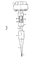
- the embodiment of the one-hand soldering device shown in the drawing consists of a soldering iron 1 with a soldering tip 2 which is attached to the end of a heating element 3. Solder wire is advanced with the aid of a not shown, known per se solder feed device through a feed tube 4, which is connected adjacent to the soldering iron 1 with a rigid end piece 10, which is attached to the soldering iron 1 via a fastening tab 6.
- a clamping piece 8 is pushed onto the tubular rigid end piece 10 of the feed pipe 4, which can be fixed in a predetermined position on the end piece 10.
- the clamping piece 8 carries one end of the spring 7, which according to FIG.
- the clamping piece 8 has a forwardly extending projection which, provided with a threaded bore, cooperates with the rear end of the mouthpiece 5 in order to fix the starting position of the free end of the mouthpiece 5 and thus the position of the portion of the solder wire 11 which projects from the mouthpiece.
- the method of operation of the one-hand soldering device described above is as follows:
- the solder wire is advanced according to the setting of the device, for example by actuation by a switch installed on the soldering iron, so that one end of the solder wire 11 protrudes from the mouthpiece 5 and lies adjacent to the soldering tip 2 .
- the soldering iron is guided in such a way that the solder wire initially rests on the workpiece, whereupon the soldering iron is pressed down in order to bring the solder wire into contact with the soldering tip 2.
- the mouthpiece 5 interlocks against the action of the spring 7 in the direction of the soldering tip or the heating element of the soldering iron.
- the mouthpiece 5 When the solder melts under the action of the hot soldering tip, the mouthpiece 5 is released again and moved by the spring 7 at a distance from the soldering tip, so that the drainage of the flux from the soldering wire is largely prevented, since the free end of the soldering wire is in an area is moved, which is no longer too high.
Landscapes
- Engineering & Computer Science (AREA)
- Mechanical Engineering (AREA)
- Electric Connection Of Electric Components To Printed Circuits (AREA)
- Adornments (AREA)
Claims (5)
Priority Applications (1)
| Application Number | Priority Date | Filing Date | Title |
|---|---|---|---|
| AT83108894T ATE20318T1 (de) | 1982-09-08 | 1983-09-08 | Einhand-loetgeraet. |
Applications Claiming Priority (2)
| Application Number | Priority Date | Filing Date | Title |
|---|---|---|---|
| DE8225325U | 1982-09-08 | ||
| DE8225325U DE8225325U1 (de) | 1982-09-08 | 1982-09-08 | Einhand-Lötgerät |
Publications (2)
| Publication Number | Publication Date |
|---|---|
| EP0102651A1 EP0102651A1 (fr) | 1984-03-14 |
| EP0102651B1 true EP0102651B1 (fr) | 1986-06-11 |
Family
ID=6743487
Family Applications (1)
| Application Number | Title | Priority Date | Filing Date |
|---|---|---|---|
| EP83108894A Expired EP0102651B1 (fr) | 1982-09-08 | 1983-09-08 | Appareil à braser pour la manipulation à une seule main |
Country Status (3)
| Country | Link |
|---|---|
| EP (1) | EP0102651B1 (fr) |
| AT (1) | ATE20318T1 (fr) |
| DE (2) | DE8225325U1 (fr) |
Families Citing this family (1)
| Publication number | Priority date | Publication date | Assignee | Title |
|---|---|---|---|---|
| AT387927B (de) * | 1983-02-21 | 1989-04-10 | Prenco Ag | Loetstation |
Family Cites Families (2)
| Publication number | Priority date | Publication date | Assignee | Title |
|---|---|---|---|---|
| US2303947A (en) * | 1940-08-26 | 1942-12-01 | Sidney A Moore | Soldering iron |
| SE416275B (sv) * | 1979-03-16 | 1980-12-15 | Jerker Rosen | Frammatningsanordning for trad- och bandmaterial vid lodningsarbete |
-
1982
- 1982-09-08 DE DE8225325U patent/DE8225325U1/de not_active Expired
-
1983
- 1983-09-08 AT AT83108894T patent/ATE20318T1/de not_active IP Right Cessation
- 1983-09-08 EP EP83108894A patent/EP0102651B1/fr not_active Expired
- 1983-09-08 DE DE8383108894T patent/DE3364075D1/de not_active Expired
Also Published As
| Publication number | Publication date |
|---|---|
| EP0102651A1 (fr) | 1984-03-14 |
| ATE20318T1 (de) | 1986-06-15 |
| DE8225325U1 (de) | 1983-03-24 |
| DE3364075D1 (en) | 1986-07-17 |
Similar Documents
| Publication | Publication Date | Title |
|---|---|---|
| EP0749808B1 (fr) | Dispositif de transport d'un magasin pour vis en forme de bande | |
| DE19522814A1 (de) | Transportvorrichtung für ein streifenförmiges Schraubenmagazin | |
| DE3825048A1 (de) | Loetkolben | |
| EP0102651B1 (fr) | Appareil à braser pour la manipulation à une seule main | |
| EP0622718A1 (fr) | Levier de commande | |
| DE3236263A1 (de) | Automatische fuehrungsvorrichtung fuer draehte | |
| EP0138072A1 (fr) | Equipement de soudage pour souder bout à bout des pièces, notamment pour braser bout à bout des câbles | |
| EP0016893A1 (fr) | Fer à souder | |
| DE2450018A1 (de) | Vorrichtung zum verbinden der enden von garnen aus thermoplastischen faeden durch verschweissen | |
| EP0243647B1 (fr) | Disjoncteur avec déclenchement thermique | |
| DE3046537C1 (de) | Vorrichtung fuer elektrische Loetkolben zur Laengenregelung und zum automatischen Vorschub des Loetdrahtes zur Loetspitze | |
| DE19737148B4 (de) | Transporteinheit | |
| DE8032858U1 (de) | Vorrichtung für elektrische Lötkolben mit Längenregelung und automatischen Vorschub des Lötdrahtes zur Lötspitze | |
| DE8328042U1 (de) | Löteinrichtung zum Stumpflöten von Teilen, insbesondere zum Stumpfhartlöten von Drähten | |
| CH596932A5 (en) | Electric hand soldering iron contg. spool of solder wire | |
| DE69511155T2 (de) | Einstellungsvorrichtung für einen Bowdenzug | |
| DE2332230A1 (de) | Drahtbefestigungsvorrichtung | |
| DE7124913U (de) | Befestigung eines Endes der Hülle eines Bowdenzuges am Gehäuse einer der Verstellung des Kernes des Bowdenzuges dienenden Einrichtung | |
| CH665797A5 (en) | Hand-held cutter for foam insulation - basically consists of frame members holding resistance-heated wire on bow whose arms can be set and locked at desired angle | |
| DE2300746C3 (de) | Vorrichtung zur Einstellung der Auslösestromstärke an einem Thermorelais | |
| DE8700939U1 (de) | Elektrische Schaltvorrichtung | |
| DE3543467A1 (de) | Maschine zu setzen von oesen | |
| DE1814838A1 (de) | Vorrichtung zur waermeabhaengigen Steuerung von elektrisch betriebenen Geraeten | |
| DE1197141B (de) | Vorrichtung zur Festlegung von abisolierten Schaltdraehten an Isolierstoffplatten von Fernmelde-, insbesondere Fernsprechanlagen | |
| WO1990003649A1 (fr) | Appareil manuel pour transferer des anneaux de marquage sur des cables conducteurs et dispositif de marquage correspondant |
Legal Events
| Date | Code | Title | Description |
|---|---|---|---|
| PUAI | Public reference made under article 153(3) epc to a published international application that has entered the european phase |
Free format text: ORIGINAL CODE: 0009012 |
|
| AK | Designated contracting states |
Designated state(s): AT BE CH DE FR GB IT LI LU NL SE |
|
| RAP1 | Party data changed (applicant data changed or rights of an application transferred) |
Owner name: COOPER INDUSTRIES INC. |
|
| 17P | Request for examination filed |
Effective date: 19840911 |
|
| GRAA | (expected) grant |
Free format text: ORIGINAL CODE: 0009210 |
|
| AK | Designated contracting states |
Kind code of ref document: B1 Designated state(s): AT BE CH DE FR GB IT LI LU NL SE |
|
| PG25 | Lapsed in a contracting state [announced via postgrant information from national office to epo] |
Ref country code: NL Effective date: 19860611 Ref country code: BE Effective date: 19860611 |
|
| REF | Corresponds to: |
Ref document number: 20318 Country of ref document: AT Date of ref document: 19860615 Kind code of ref document: T |
|
| PG25 | Lapsed in a contracting state [announced via postgrant information from national office to epo] |
Ref country code: SE Effective date: 19860630 |
|
| ITF | It: translation for a ep patent filed | ||
| REF | Corresponds to: |
Ref document number: 3364075 Country of ref document: DE Date of ref document: 19860717 |
|
| ET | Fr: translation filed | ||
| NLV1 | Nl: lapsed or annulled due to failure to fulfill the requirements of art. 29p and 29m of the patents act | ||
| PLBE | No opposition filed within time limit |
Free format text: ORIGINAL CODE: 0009261 |
|
| STAA | Information on the status of an ep patent application or granted ep patent |
Free format text: STATUS: NO OPPOSITION FILED WITHIN TIME LIMIT |
|
| 26N | No opposition filed | ||
| PGFP | Annual fee paid to national office [announced via postgrant information from national office to epo] |
Ref country code: LU Payment date: 19920703 Year of fee payment: 10 |
|
| PGFP | Annual fee paid to national office [announced via postgrant information from national office to epo] |
Ref country code: GB Payment date: 19920810 Year of fee payment: 10 |
|
| PGFP | Annual fee paid to national office [announced via postgrant information from national office to epo] |
Ref country code: AT Payment date: 19920811 Year of fee payment: 10 |
|
| ITTA | It: last paid annual fee | ||
| EPTA | Lu: last paid annual fee | ||
| PG25 | Lapsed in a contracting state [announced via postgrant information from national office to epo] |
Ref country code: LU Free format text: LAPSE BECAUSE OF NON-PAYMENT OF DUE FEES Effective date: 19930908 Ref country code: GB Effective date: 19930908 Ref country code: AT Effective date: 19930908 |
|
| PGFP | Annual fee paid to national office [announced via postgrant information from national office to epo] |
Ref country code: FR Payment date: 19930930 Year of fee payment: 11 |
|
| PGFP | Annual fee paid to national office [announced via postgrant information from national office to epo] |
Ref country code: CH Payment date: 19931202 Year of fee payment: 11 |
|
| GBPC | Gb: european patent ceased through non-payment of renewal fee |
Effective date: 19930908 |
|
| PG25 | Lapsed in a contracting state [announced via postgrant information from national office to epo] |
Ref country code: LI Effective date: 19940930 Ref country code: CH Effective date: 19940930 |
|
| PG25 | Lapsed in a contracting state [announced via postgrant information from national office to epo] |
Ref country code: FR Effective date: 19950531 |
|
| REG | Reference to a national code |
Ref country code: CH Ref legal event code: PL |
|
| REG | Reference to a national code |
Ref country code: FR Ref legal event code: ST |
|
| PGFP | Annual fee paid to national office [announced via postgrant information from national office to epo] |
Ref country code: DE Payment date: 19961126 Year of fee payment: 14 |
|
| PG25 | Lapsed in a contracting state [announced via postgrant information from national office to epo] |
Ref country code: DE Free format text: LAPSE BECAUSE OF NON-PAYMENT OF DUE FEES Effective date: 19980603 |