EP0102659B1 - Circuit de contrôle de la vitesse du moteur d'une machine à laver - Google Patents
Circuit de contrôle de la vitesse du moteur d'une machine à laver Download PDFInfo
- Publication number
- EP0102659B1 EP0102659B1 EP83201110A EP83201110A EP0102659B1 EP 0102659 B1 EP0102659 B1 EP 0102659B1 EP 83201110 A EP83201110 A EP 83201110A EP 83201110 A EP83201110 A EP 83201110A EP 0102659 B1 EP0102659 B1 EP 0102659B1
- Authority
- EP
- European Patent Office
- Prior art keywords
- scr
- supply voltage
- mains supply
- voltage
- state
- Prior art date
- Legal status (The legal status is an assumption and is not a legal conclusion. Google has not performed a legal analysis and makes no representation as to the accuracy of the status listed.)
- Expired
Links
- 238000005406 washing Methods 0.000 title claims description 13
- 238000010304 firing Methods 0.000 claims description 13
- 239000004065 semiconductor Substances 0.000 claims description 4
- 230000000694 effects Effects 0.000 description 5
- 238000001514 detection method Methods 0.000 description 4
- 230000001934 delay Effects 0.000 description 2
- 238000010586 diagram Methods 0.000 description 2
- 238000001035 drying Methods 0.000 description 2
- 230000036039 immunity Effects 0.000 description 2
- 238000000034 method Methods 0.000 description 2
- 238000010079 rubber tapping Methods 0.000 description 2
- 230000002411 adverse Effects 0.000 description 1
- 230000002457 bidirectional effect Effects 0.000 description 1
- 230000002452 interceptive effect Effects 0.000 description 1
- 230000000630 rising effect Effects 0.000 description 1
- 230000001052 transient effect Effects 0.000 description 1
- 238000004804 winding Methods 0.000 description 1
Images


Classifications
-
- H—ELECTRICITY
- H02—GENERATION; CONVERSION OR DISTRIBUTION OF ELECTRIC POWER
- H02H—EMERGENCY PROTECTIVE CIRCUIT ARRANGEMENTS
- H02H7/00—Emergency protective circuit arrangements specially adapted for specific types of electric machines or apparatus or for sectionalised protection of cable or line systems, and effecting automatic switching in the event of an undesired change from normal working conditions
- H02H7/08—Emergency protective circuit arrangements specially adapted for specific types of electric machines or apparatus or for sectionalised protection of cable or line systems, and effecting automatic switching in the event of an undesired change from normal working conditions for dynamo-electric motors
- H02H7/0833—Emergency protective circuit arrangements specially adapted for specific types of electric machines or apparatus or for sectionalised protection of cable or line systems, and effecting automatic switching in the event of an undesired change from normal working conditions for dynamo-electric motors for electric motors with control arrangements
- H02H7/0844—Fail safe control, e.g. by comparing control signal and controlled current, isolating motor on commutation error
-
- Y—GENERAL TAGGING OF NEW TECHNOLOGICAL DEVELOPMENTS; GENERAL TAGGING OF CROSS-SECTIONAL TECHNOLOGIES SPANNING OVER SEVERAL SECTIONS OF THE IPC; TECHNICAL SUBJECTS COVERED BY FORMER USPC CROSS-REFERENCE ART COLLECTIONS [XRACs] AND DIGESTS
- Y10—TECHNICAL SUBJECTS COVERED BY FORMER USPC
- Y10S—TECHNICAL SUBJECTS COVERED BY FORMER USPC CROSS-REFERENCE ART COLLECTIONS [XRACs] AND DIGESTS
- Y10S388/00—Electricity: motor control systems
- Y10S388/90—Specific system operational feature
- Y10S388/903—Protective, e.g. voltage or current limit
-
- Y—GENERAL TAGGING OF NEW TECHNOLOGICAL DEVELOPMENTS; GENERAL TAGGING OF CROSS-SECTIONAL TECHNOLOGIES SPANNING OVER SEVERAL SECTIONS OF THE IPC; TECHNICAL SUBJECTS COVERED BY FORMER USPC CROSS-REFERENCE ART COLLECTIONS [XRACs] AND DIGESTS
- Y10—TECHNICAL SUBJECTS COVERED BY FORMER USPC
- Y10S—TECHNICAL SUBJECTS COVERED BY FORMER USPC CROSS-REFERENCE ART COLLECTIONS [XRACs] AND DIGESTS
- Y10S388/00—Electricity: motor control systems
- Y10S388/907—Specific control circuit element or device
- Y10S388/917—Thyristor or scr
- Y10S388/919—Triggered by resistor or capacitor
Definitions
- This invention relates to a washing machine motor speed control circuit including a semiconductor controlled rectifier (SCR) arranged in series with the motor and a trigger circuit for firing the SCR at a controllably variable instant in each half cycle of an AC mains supply voltage applied to the series circuit in order to control the average power applied to the motor.
- SCR semiconductor controlled rectifier
- Circuits of the type defined above are well known, e.g. from EP-A 1-0011 503, and typically include a servo loop which enables the speed of the motor, and hence of the drum, to be kept substantially constant at any value within a predetermined range of values irrespective of the type of wash load in the drum.
- the range of values is very wide and, in terms of drum speed, extends from a relatively low value (for example 35 r.p.m.) for washing and rinsing to a relatively high value (for example 1,000 r.p.m.) for spin drying the load.
- the instant in each half cycle at which the trigger circuit fires the SCR is controllably variable from a high value (e.g. 150°) at which a relatively low average power is applied to the motor, to a low value (e.g. 18°) at which a relatively high average power is applied to the motor.
- a high value e.g. 150°
- a low value e.g. 18°
- An object of the invention is at least to mitigate the above-mentioned disadvantages.
- a washing machine motor speed control circuit including a semiconductor controlled rectifier (SCR) arranged in series with the motor and a trigger circuit for firing the SCR at a controllably variable instant in each half cycle of an AC mains supply voltage, applied to the series circuit, in order to control the average power applied to the motor, characterised in that the control circuit further includes means for detecting a short circuit fault in said SCR comprising a bistable device arranged to be set to a first state each time the modulus of the mains supply voltage drops below a first value and thereafter to be set to a second state only if the modulus of the voltage across the SCR subsequently rises to a second value greater than the first value, and a logic circuit which causes the mains supply voltage to the motor to be disconnected if the bistable device is not set to the second state in each half cycle of the mains supply voltage for a given number, exceeding two, of consecutive half cycles of the same polarity and if the bistable device is not set to the second state in each half cycle of the
- Control circuits using SCRs rely on the fact that the SCR switches itself off at the end of each half cycle in which it has been fired when the current through its main electrodes drops below the holding current of the SCR concerned. Due to the inductance of the motor, however, the current lags the voltage and the SCR is therefore not switched off until some time (for example a period of 0.5 to 2.0 mS) after the applied voltage has passed through zero. This period depends not only upon the inductance of the motor but also upon the motor speed at the instant concerned and is hence indeterminate. Also, as mentioned above, the firing angle of the SCR can be varied between wide limits in each half cycle.
- the bistable device can be strobed over very wide limits. This can be explained as follows.
- the modulus of the voltage is dropping towards zero and the bistable device is set to the first state when the modulus drops below the first value.
- the bistable device is always in the first state irrespective of the state of the SCR.
- the voltage across the SCR then passes through zero and, if the SCR becomes non-conducting, rises until its modulus reaches the second value, whereupon the bistable device is set to the second state. Since in normal circumstances, the SCR becomes non-conductive early in each half cycle, the bistable device may be strobed to check its state at any time from the instant the SCR becomes non-conductive up to just before the bistable device is set to the first state at the end of the half cycle.
- the bistable device cannot be set to its second state and this is used as an indication of the presence of a short circuit fault in the SCR.
- the first and second values are preferably not less than 10V and 15V respectively.
- washing machines having a motor speed control circuit using an SCR give an occasional audible out-of-balance "bump" and that this is caused by the SCR failing to come out of conduction due to the presence of interfering voltage or current spikes.
- this can very occasionally happen on two consecutive half cycles of the supply voltage but we have noted no case where it occurs on three or more consecutive half cycles.
- the logic circuit is arranged to respond only if a short-circuit SCR condition is detected (i.e. the bistable device not being set to the second state) for at least three consecutive half cycles of the same polarity or of alternating polarity. Under these conditions, the mains supply to the motor is only disconnected if the SCR develops a short circuit fault.
- the SCR is a bidirectional device (triac).
- Triac bidirectional device
- Such a device effectively includes two parallel diodes with opposing conductivity directions and either one or both diodes may develop a short circuit. If one diode becomes short-circuited, then the bistable device cannot be set to its second state in those half cycles having the polarity normally conducted by that diode. Therefore the control circuit responds even if only one of the two diodes is short-circuited.
- the logic circuit preferably causes the mains supply voltage to the motor to be disconnected if the bistable device is not set to the second state in each half cycle of the mains supply voltage for four consecutive half cycles of the same polarity and if the bistable device is not set to the second state in each half cycle of the mains supply voltage for four consecutive half cycles of alternating polarity.
- a fully short-circuited triac is detected in 40 mS with a 50 Hz mains supply voltage and a half short-circuited triac is detected in 70-80 mS.
- the logic circuit When a short-circuited SCR has been detected, the logic circuit causes the mains supply voltage to the motor to be disconnected.
- the mains supply voltage is disconnected by at least one electric switch operable by the logic circuit and the control circuit includes means for locking the switch in its operated state until the main supply voltage to the washing machine is switched off by the user.
- the switch(es) may be of the electro-magnetic or electronic type.
- US-A-3914675 discloses an electric motor control circuit including a series combination of a semiconductor controlled rectifier and the motor connected to an electrical supply and a trigger circuit for periodically firing the SCR in order to control the average power supplied to the motor.
- Means are provided for detecting a short-circuit fault in the SCR, these means comprising an impedance sensor which monitors the impedance of the SCR and a bistable device which is set by the impedance sensor to a first state if the impedance of the SCR is low for longer than a predetermined period of time. The setting of the bistable device results in the cutting off of the supply.
- This US patent also discloses that the voltage drop across a power-switching SCR can be monitored, a very low voltage drop indicating conduction by the SCR.
- the electrical supply in this known circuit is, however, essentially DC.
- the control circuit includes a series circuit comprising a motor M having an armature A and a field winding F, a triac SCR, and the break contact R1 of a relay R.
- This series circuit is connected across input terminals L and N for an AC mains supply voltage of, for example, 240V 50 Hz.
- a trigger circuit TR is connected to the gate electrode of triac SCR and generates firing pulses for the triac at a controllably variable firing angle in each half cycle of the mains supply voltage.
- Such trigger circuits are well known and, by controlling the firing angle, control the speed of the motor and hence the rotational speed of the drum containing the wash load.
- Resistors R1 and R2 form a voltage divider for the mains voltage across terminals Land N.
- Resistors R3 and R2 form a voltage divider for a DC supply voltage (e.g. 12V) between rail DC and terminal N.
- the DC voltage is obtained from the mains supply voltage in conventional manner by means not shown in the drawings.
- the common tapping point of the two voltage dividers is connected to the input of a first voltage zero crossing detector ZX1.
- resistors R4 and R5 form a voltage divider for the AC voltage across triac SCR and resistors R6 and R5 form a voltage divider for the DC voltage on the rail DC.
- the common tapping point of these two dividers is connected to the input of a second voltage zero crossing detector ZX2.
- detector ZX1 is connected to the reset input of a bistable device BD and also to a strobing circuit STR.
- the output of detector ZX2 is connected to the set input of bistable device BD.
- the outputs of circuit STR and device BD are connected to respective inputs of an AND-gate AN1 the output of which is connected to a logic circuit LOG.
- the output of circuit LOG controls the electromagnetic relay R.
- the set and reset input signals to the device BD are referred to as AS (anode sense) and ZC (mains zero crossing) respectively.
- the output signal of device BD is referred to as LAS (latched anode sense).
- Zero crossing detector ZX1 and the values of resistors R1 and R2 are so arranged that the output of the detector ZX1 is a logic '1' only if the modulus of the voltage on terminal L drops below a first predetermined value, for example 30V in the case of a 240V AC mains supply voltage.
- signal ZC is a '1' only if the voltage on terminal L lies between +30V and -30V.
- Detector ZX2 and the values of resistors R4 and R5 are so arranged that the output signal of detector ZX2 is a logic'0' if the modulus of the voltage across the triac SCR rises to a second value, e.g. 60V, higher than the above-mentioned first value.
- signal AS is a logic '1' if the voltage across triac SCR is between +60V and -60V.
- the zero crossing detectors ZX1 and ZX2 in the practical embodiment were transistor circuits supplied from the 12V DC supply rail DC in common with the other circuits.
- Voltage dividers R1, R2 and R4, R5 divide the mains voltages concerned down to levels that can be readily handled by these circuits.
- the zero crossing detectors typically comprise two voltage comparators fed with the input voltage to the detector and respective reference voltages for the two levels of detection. In the case of detector ZX1, these two levels would correspond to +30V and -30V on terminal L.
- the DC voltage dividers R3, R2 and R6, R5 are arranged to provide a positive DC bias, for example 3.8V, on the inputs to the detectors ZX1 and ZX2.
- Each detector may, for example, comprise two voltage comparators a first of which is arranged to respond (give a logic '1' output) to a voltage above +1.6V and the second of which is arranged to respond to a voltage above +6V.
- the output of the second comparator is inverted and fed to one input of an AND-gate the other input of which is connected to the output of the first comparator.
- the output of the AND-gate is thus'1' if the input voltage to the detector concerned is between + 1.6V and +6V.
- the value of resistor R1 is chosen in relation to resistor R2 such that a voltage of 30V on terminal L produces a divided-down voltage of 2.2V at the input to detector ZX1.
- detector ZX1 gives a '1' output only if the voltage at terminal L is between +30V and -30V. Since these voltages occur close to the zero crossing point, a short'1' pulse is given each time the mains supply voltage passes through zero.
- resistors R4 and R5 are chosen such that zero crossing detector ZX2, which is identical to detector ZX1, gives a '1' output only when the voltage across triac SCR is between +60V and -60V.
- bistable device BD in response to input signals ZC and AS will now be described with reference to Figure 2.
- the device BD comprises an OR-gate OR the output of which is connected to the inverting (D) input of a clocked D-type, or delay, flip-flop DL.
- the Q output of flip-flop DL provides the output signal LAS of the bistable device and the Q input is connected to one input of an AND-gate AN2, to the other input of which the signal AS is connected.
- the output of gate AN2 is connected to a further input of the gate OR.
- signal ZC goes to '1'
- signal LAS goes to '0' on receipt of the next clock pulse on lead CL and Q going to '1' enables gate AN2.
- Signal AS is already '1' and this maintains the '1' at the 0 input of flip-flop DL when signal ZC goes to '0'.
- signal AS goes to '0'
- the signal on the 0 input of flip-flop DL goes to '0' and signal LAS goes to '1' on receipt of the next clock pulse on lead CL.
- the repetition rate of the clock pulses is preferably relatively high (e.g. 20 kHz) compared with the frequency of the mains supply voltage.
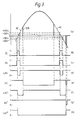
- waveform (a) of which shows a full sine wave AC representing the voltage of the mains supply and also the voltage across the triac SCR when the latter is not being fired in any half cycle, and a thickened line waveform SCR which represents the voltage across the triac SCR when the latter is being fired.
- waveform (b) shows the zero crossing signal ZC, which is '1' only when the main supply voltage is between +30V and -30V.
- this signal comprises a relatively short pulse at each zero crossing of the mains supply voltage. This pulse would be narrower, of course, if a lower detection voltage were used.
- the first voltage level should preferably be at least 10V.
- Waveform (c) shows the signal AS that exists in the case where the triac SCR is not being fired in any half cycle of the mains supply voltage. As can be seen, this signal is '1' only so long as the voltage across the SCR is between- +60V and -60V.
- Waveform (d) shows the output signal LAS of bistable BD when fed with the input signals shown in waveforms (b) and (c).
- the width of the '1' pulses in signal ZC would be larger than those of signal AS-that is to say that signal ZC would go to '1' before signal AS and remain at '1' until after signal AS has reverted to '0'.
- signal LAS would, subject to the clocking instants, be the increase of signal ZC irrespective of the state of signal AS at any time.
- the second value of the voltage greater than the first is that the voltage across the triac SCR is more sensitive to interference than is the mains supply voltage. Whilst the second value of 60V given in the above example gives excellent freedom from interference, a lower value could obviously be used. Preferably, however, this second value should not be less than 15 volts.
- Triac SCR is then fired by the trigger circuit at a firing angle of about 150° and the voltage across it, as shown by the thick line in waveform (a), drops substantially to zero.
- Signal AS' accordingly goes to '1' but this has no effect on signal LAS' which, therefore, is reset to '0' at the next rising edge of signal ZC.
- Waveforms (a) and (e) show what would normally be the latest instant at which the triac ceases to conduct. In most cases the triac would cease to conduct rather earlier in each half cycle than is shown in the Figure-in fact in some cases it would cease to conduct before the arrival of the falling edge of signal AS in waveform (c), i.e. before the modulus of the mains supply voltage reaches 60V. This would not, of course, affect signal AS which would remain at '1' until the voltage across the SCR reached the second value of 60V.
- any firing pulse that may occur before the triac ceases to conduct in any half cycle would of course have no effect and would be lost.
- the bistable device cannot be set and signal LAS remains at '0'. If, for example, the triac is short-circuited only for the positive half cycles then the appropriate signal AS" (waveform (g)) wil remain at '1' and the resulting signal LAS" (waveform (h)) cannot reach the '1' (set) state during any of these half cycles.
- the signal LAS may be strobed at about the middle of each half wave cycle by means of the strobe circuit STR and gate AN1.
- the strobing circuit STR may include a counter which is driven by clock pulses and which is set to its count state by each zero crossing pulse ZC and gives an output pulse and resets to zero when it reaches a predetermined count value.
- the clock pulse repetition rate and the count value can be chosen to provide a strobing pulse to the one input of gate AN1 approximately in the middle of each half cycle.
- Another method would be to feed each zero crossing pulse ZC into a clocked shift register which delays the pulse for about one-quarter of a cycle of the mains supply voltage.
- the operation of the logic circuit LOG is most simply explained with reference to the flow chart given in Figure 4.
- the Table shows the sequence of events leading to switching off the motor after seven half cycles. If the triac had only its other diode portion short-circuited (i.e. affecting the even-numbered half cycles), then using the sequence in the Table the motor would be switched off after eight half cycles.
- the motor is switched off by the logic circuit operating a disconnection switch.
- the switch is an electromagnetic relay R which, when operated by the logic circuit LOG, disconnects the mains supply voltage to the motor at its break contact R1.
- the switch may be of the wholly electronic type well known to those skilled in the art.
- relay R is provided with a locking circuit, not shown, which for example locks the relay via one of-its own contacts across the DC supply. In such a case, the relay can only be released by switching off the mains supply to the washing machine, thereby providing complete safety of operation.
Landscapes
- Control Of Ac Motors In General (AREA)
- Protection Of Generators And Motors (AREA)
Claims (5)
Applications Claiming Priority (2)
| Application Number | Priority Date | Filing Date | Title |
|---|---|---|---|
| GB8222699 | 1982-08-06 | ||
| GB08222699A GB2125642B (en) | 1982-08-06 | 1982-08-06 | Washing machine motor speed control circuit |
Publications (2)
| Publication Number | Publication Date |
|---|---|
| EP0102659A1 EP0102659A1 (fr) | 1984-03-14 |
| EP0102659B1 true EP0102659B1 (fr) | 1987-04-08 |
Family
ID=10532153
Family Applications (1)
| Application Number | Title | Priority Date | Filing Date |
|---|---|---|---|
| EP83201110A Expired EP0102659B1 (fr) | 1982-08-06 | 1983-07-28 | Circuit de contrôle de la vitesse du moteur d'une machine à laver |
Country Status (5)
| Country | Link |
|---|---|
| US (1) | US4524403A (fr) |
| EP (1) | EP0102659B1 (fr) |
| JP (1) | JPS5941117A (fr) |
| DE (1) | DE3370908D1 (fr) |
| GB (1) | GB2125642B (fr) |
Cited By (2)
| Publication number | Priority date | Publication date | Assignee | Title |
|---|---|---|---|---|
| DE3833701A1 (de) * | 1988-10-04 | 1990-04-05 | Ako Werke Gmbh & Co | Elektrische steuerschaltung eines universalmotors |
| DE3833702A1 (de) * | 1988-10-04 | 1990-04-05 | Ako Werke Gmbh & Co | Steuerschaltung eines universalmotors |
Families Citing this family (10)
| Publication number | Priority date | Publication date | Assignee | Title |
|---|---|---|---|---|
| US4879623A (en) * | 1985-12-02 | 1989-11-07 | Caterpillar Industrial Inc. | Voltage transients |
| JPH02136698A (ja) * | 1988-11-18 | 1990-05-25 | Agency Of Ind Science & Technol | 対流伝熱面における熱伝達促進装置 |
| DE3924653A1 (de) * | 1989-07-26 | 1991-01-31 | Telefunken Electronic Gmbh | Ueberwachungsschaltung fuer einen laststromkreis |
| DE4104272A1 (de) * | 1991-02-13 | 1992-08-20 | Licentia Gmbh | Verfahren zum schutz gegen ueberhoehte antriebsmotordrehzahlen elektronisch gesteuerter geraete, insbesondere fuer haushaltwaschmaschinen und schaltungsanordnung zur durchfuehrung des verfahrens |
| IT1256545B (it) * | 1992-03-09 | 1995-12-07 | Bitron Video | Circuito di pilotaggio di un motore elettrico, del tipo di quelli usati per produrre la rotazione di un cestello di una macchina lavabiancheria |
| DE102007036667A1 (de) * | 2007-08-03 | 2009-02-26 | BSH Bosch und Siemens Hausgeräte GmbH | Einrichtung und Verfahren zum Betreiben eines elektrischen Verbrauchers |
| GB2469130B (en) * | 2009-04-04 | 2014-01-29 | Dyson Technology Ltd | Control system for an electric machine |
| GB2469129B (en) | 2009-04-04 | 2013-12-11 | Dyson Technology Ltd | Current controller for an electric machine |
| GB2469140B (en) | 2009-04-04 | 2013-12-11 | Dyson Technology Ltd | Control of an electric machine |
| GB2469128A (en) * | 2009-04-04 | 2010-10-06 | Dyson Technology Ltd | Generating control signals for an electric machine from a position sensor |
Family Cites Families (6)
| Publication number | Priority date | Publication date | Assignee | Title |
|---|---|---|---|---|
| US3914675A (en) * | 1973-09-17 | 1975-10-21 | Gen Electric | Fault detector circuit for electric vehicle control |
| JPS51103333A (fr) * | 1975-03-07 | 1976-09-11 | Matsushita Electric Industrial Co Ltd | |
| FR2377750A7 (fr) * | 1977-01-13 | 1978-08-11 | Candy Spa | Dispositif limiteur de vitesse de moteurs asynchrones utilises notamment dans les machines a laver |
| JPS5579679A (en) * | 1978-12-08 | 1980-06-16 | Hitachi Ltd | Controller for transistor chopper |
| IT1110628B (it) * | 1979-01-30 | 1985-12-23 | Sp El Srl | Circuito per la protezione automatica dei transistori di potenza particolarmente per convertitori a commutazione o simili |
| US4263646A (en) * | 1979-04-27 | 1981-04-21 | General Electric Company | Missed commutation detector and safeguard arrangement |
-
1982
- 1982-08-06 GB GB08222699A patent/GB2125642B/en not_active Expired
-
1983
- 1983-07-21 US US06/515,734 patent/US4524403A/en not_active Expired - Fee Related
- 1983-07-28 DE DE8383201110T patent/DE3370908D1/de not_active Expired
- 1983-07-28 EP EP83201110A patent/EP0102659B1/fr not_active Expired
- 1983-08-03 JP JP58141270A patent/JPS5941117A/ja active Pending
Cited By (2)
| Publication number | Priority date | Publication date | Assignee | Title |
|---|---|---|---|---|
| DE3833701A1 (de) * | 1988-10-04 | 1990-04-05 | Ako Werke Gmbh & Co | Elektrische steuerschaltung eines universalmotors |
| DE3833702A1 (de) * | 1988-10-04 | 1990-04-05 | Ako Werke Gmbh & Co | Steuerschaltung eines universalmotors |
Also Published As
| Publication number | Publication date |
|---|---|
| JPS5941117A (ja) | 1984-03-07 |
| EP0102659A1 (fr) | 1984-03-14 |
| DE3370908D1 (en) | 1987-05-14 |
| US4524403A (en) | 1985-06-18 |
| GB2125642A (en) | 1984-03-07 |
| GB2125642B (en) | 1985-10-02 |
Similar Documents
| Publication | Publication Date | Title |
|---|---|---|
| US4879624A (en) | Power controller | |
| US4524403A (en) | Washing machine motor speed control circuit | |
| JPH1062486A (ja) | 交流回路の直列アーク故障検出装置 | |
| CA2388654C (fr) | Unite de commande de moteur a conservation d'energie | |
| EP0254992A2 (fr) | Détecteur pour la perte de puissance à courant alternatif | |
| EP0273196A2 (fr) | Détecteur de structures à plusieurs niveaux pour un signal unique | |
| US4342076A (en) | Transistor turn off current sensing circuit | |
| US5712910A (en) | Ring trip circuit having a simple trip detecting circuit of a high response speed | |
| JP2648536B2 (ja) | 電源切換装置 | |
| US3627967A (en) | Power switch short circuit detector for edm | |
| US4357645A (en) | System for detecting faulty SCR's | |
| US3748537A (en) | Protection device for hammer driving circuits | |
| EP2439546A1 (fr) | Procédé de détection d'une surintensité dans un triac | |
| US4134025A (en) | Electric switch arrangement for use as a current supply switching means for a bipolar electric load | |
| US4145647A (en) | Arrangement for controlling the speed and rotary direction of a three-phase asynchronous motor | |
| EP0142310B1 (fr) | Dispositif électrique à détecteur à stockage de charge | |
| JP2552042B2 (ja) | Scrの導電測定方法及び測定装置 | |
| US3403269A (en) | Frequency responsive rc timing circuit for detecting either lack of input or overextended presence of input | |
| US4683413A (en) | Reducing power consumption and monitoring synchronous running of three-phase electric motors | |
| EP0560186B1 (fr) | Circuit de pilotage pour un moteur électrique de type utilisé pour la rotation d'un tambour d'une machine à laver le linge | |
| SU1014090A1 (ru) | Устройство дл запуска трехфазной электроустановки от изменени чередовани и обрыва фазы | |
| US5057963A (en) | Opposite phase detecting device for alternating current electrical equipment | |
| CA1136703A (fr) | Detecteur de cretes de tension | |
| SU1591179A1 (ru) | Устройство для обнаружения отказов в шаговом электроприводе | |
| SU1338033A2 (ru) | Устройство дл контрол последовательности импульсов |
Legal Events
| Date | Code | Title | Description |
|---|---|---|---|
| PUAI | Public reference made under article 153(3) epc to a published international application that has entered the european phase |
Free format text: ORIGINAL CODE: 0009012 |
|
| AK | Designated contracting states |
Designated state(s): DE FR GB IT |
|
| 17P | Request for examination filed |
Effective date: 19840529 |
|
| GRAA | (expected) grant |
Free format text: ORIGINAL CODE: 0009210 |
|
| AK | Designated contracting states |
Kind code of ref document: B1 Designated state(s): DE FR GB IT |
|
| PG25 | Lapsed in a contracting state [announced via postgrant information from national office to epo] |
Ref country code: IT Free format text: LAPSE BECAUSE OF FAILURE TO SUBMIT A TRANSLATION OF THE DESCRIPTION OR TO PAY THE FEE WITHIN THE PRESCRIBED TIME-LIMIT;WARNING: LAPSES OF ITALIAN PATENTS WITH EFFECTIVE DATE BEFORE 2007 MAY HAVE OCCURRED AT ANY TIME BEFORE 2007. THE CORRECT EFFECTIVE DATE MAY BE DIFFERENT FROM THE ONE RECORDED. Effective date: 19870408 Ref country code: FR Free format text: THE PATENT HAS BEEN ANNULLED BY A DECISION OF A NATIONAL AUTHORITY Effective date: 19870408 |
|
| REF | Corresponds to: |
Ref document number: 3370908 Country of ref document: DE Date of ref document: 19870514 |
|
| EN | Fr: translation not filed | ||
| PLBE | No opposition filed within time limit |
Free format text: ORIGINAL CODE: 0009261 |
|
| STAA | Information on the status of an ep patent application or granted ep patent |
Free format text: STATUS: NO OPPOSITION FILED WITHIN TIME LIMIT |
|
| PG25 | Lapsed in a contracting state [announced via postgrant information from national office to epo] |
Ref country code: DE Effective date: 19880401 |
|
| 26N | No opposition filed | ||
| GBPC | Gb: european patent ceased through non-payment of renewal fee | ||
| PG25 | Lapsed in a contracting state [announced via postgrant information from national office to epo] |
Ref country code: GB Free format text: LAPSE BECAUSE OF NON-PAYMENT OF DUE FEES Effective date: 19881122 |