EP0102664A1 - Feuerleitsystem für Fahrzeug oder Schiff - Google Patents
Feuerleitsystem für Fahrzeug oder Schiff Download PDFInfo
- Publication number
- EP0102664A1 EP0102664A1 EP83201180A EP83201180A EP0102664A1 EP 0102664 A1 EP0102664 A1 EP 0102664A1 EP 83201180 A EP83201180 A EP 83201180A EP 83201180 A EP83201180 A EP 83201180A EP 0102664 A1 EP0102664 A1 EP 0102664A1
- Authority
- EP
- European Patent Office
- Prior art keywords
- coordinate system
- data
- vehicle
- target
- vessel
- Prior art date
- Legal status (The legal status is an assumption and is not a legal conclusion. Google has not performed a legal analysis and makes no representation as to the accuracy of the status listed.)
- Granted
Links
Images

Classifications
-
- F—MECHANICAL ENGINEERING; LIGHTING; HEATING; WEAPONS; BLASTING
- F41—WEAPONS
- F41G—WEAPON SIGHTS; AIMING
- F41G5/00—Elevating or traversing control systems for guns
- F41G5/14—Elevating or traversing control systems for guns for vehicle-borne guns
-
- F—MECHANICAL ENGINEERING; LIGHTING; HEATING; WEAPONS; BLASTING
- F41—WEAPONS
- F41G—WEAPON SIGHTS; AIMING
- F41G3/00—Aiming or laying means
- F41G3/10—Aiming or laying means with means for compensating for canting of the trunnions
Definitions
- the invention relates to a fire control system for a vehicle or vessel, which fire control system is provided with:
- a heavy combat vehicle such as a tank
- levelling jacks since, due to the large mass of the vehicle, the recoil of the gun when fired has no appreciable effect on the position of this vehicle.
- the adjustment of levelling jacks for a combat vehicle fitted with a spring-suspended chassis on pneumatic typres and with the abovementioned fire control system is however time-consuming, and hence a disadvantage of such a combat vehicle.
- the present invention has for its object to obviate the disadvantage with the use of the above fire control system for a vehicle fitted with a spring-suspended chassis on pneumatic tyres or for a rolling vessel.
- the fire control computer comprises a (first) coordinate conversion unit for determining the elements of the transformation matrix (H) associated with the transformation from the first coordinate system to the second coordinate system, using supplied data concerning the relative angular positions measured at the axes of rotation between the target tracking unit, the turret, and the vehicle or vessel, and using data supplied by reference orientation means and concerning the angular positions with respect to the tilt of the vehicle or vessel in the second coordinate system, and for converting the angular error data obtained from the data processor in the first coordinate system into target positions in the second coordinate system, using the elements of said transformation matrix, which fire control computer further comprises a (second) coordinate conversion unit for transforming, on the basis of the data supplied by said reference orientation means, the gun aiming data determined in the second coordinate system to a third coordinate system coupled to the vehicle or vessel.
- H transformation matrix
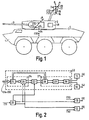
- Fig. 1 shows a three-axle combat vehicle 1, provided with a turret 2 and gun 3.
- Vehicle 1 is considered to be fitted with a spring-suspended chassis on pneumatic tyres.
- the turret 2 is rotatable about an axis 4, which is perpendicular to the roof 5 of vehicle 1.
- the gun 3 is movable in elevation about an axis 6 in the turret 2; axis 6 is oriented parallel to the roof 5.
- Mounted on the turret 2 is a target tracking unit 7 for tracking a target in range and in angles.
- the target tracking unit 7 may consist of a radar tracking apparatus, a laser range detector, an infrared tracking unit, a TV tracking unit or optical detection means (periscope, binocular), as well as combinations thereof.
- the target tracking unit 7 is biaxially connected with the turret 2, one axis 8 being oriented parallel to or coaxially with axis 4 on the turret 2 and the other axis 9 parallel to the roof 5.
- the relative motion of the turret 2 with respect to the vehicle 1 (about axis 4), the gun 3 with respect to the turret 2 (about axis 6), and the target tracking unit 7 with respect to the turret 2 (about axes 8 and 9), is achieved by servo control units 10, 11, 12 and 13, respectively, shown schematically in Fig. 1.
- the angular rotations of the turret 2 with respect to the vehicle 1 (about axis 4), the gun 3 with respect to the turret 2 (about axis 6), and the target tracking unit 7 with respect to the turret 2 (about axes 8 and 9) are measured by angle data transmitters 14, 15, 16 and 17, respectively, shown schematically in Fig. 1, which transmitters may be synchros, digital angle data transmitters, etc.
- the vehicle 1 is further provided with reference orientation means for obtaining time-reliable data about the orientation of the vehicle with respect to a fixed horizontal (second) coordinate system;
- the reference orientation means may consist of a three-axis, vertical gyroscope 18 and/or rate gyroscopes 19 and 20, shown schematically.
- the rate gyroscopes 19 and 20 are mounted on the axes 8 and 9 and furnish data about the angular velocities of the rate gyroscopes relative to the fixed horizontal plane.
- axis 9 may be tilted at an angle to the base plane of the second coordinate system through the combat vehicle being located on hilly ground and/or through the recoil of the gun 3.
- the required initial values of the tilt may be_furnished separately, for instance, by gyroscope 18.
- Fig. 2 is a block diagram of a fire control system for the combat vehicle 1 of Fig. 1.
- the fire control system contains a data processor 21, which is fed with angle and range data from the target tracking unit 7.
- the data processor 21 furnishes data about the angular deviation between the line of sight of the target tracking unit 7 and the target line of sight, and hence target positional values in a first coordinate system coupled to the target tracking unit 7 and oriented perpendicularly to the line of sight of this unit.
- a fire control computer 22 the target positional values are converted to a second, fixed horizontal coordinate system to generate thereout the target track by means of an aiming-point generator 23 and, hence, to calculate aiming values for the gun 3.
- the fire control computer 22 thereto comprises a first coordinate conversion unit 24, containing means 25 for establishing the elements of the matrix (H) associated with the transformation of the first coordinate system coupled to the target tracking unit 7 to the second coordinate system,'which means 25 is supplied with the data from the angle data transmitters 14-17 and the reference orientation means 18, 19 and 20.
- the first coordinate conversion unit 24 further contains another transformation unit 26 to provide H(z) as the target position in the second coordinate system.
- the aiming-point generator 23 is capable of generating the target track and calculating aiming values with the aid of additionally supplied data about ballistic corrections to be made and the data from rate gyroscope 18 about the gravitational direction.
- the fire control computer 22 comprises a transformation unit 27, using a matrix whose elements are calculable with the aid of the data supplied by the reference orientation means 18, 19 and 20.
- a favourable embodiment of such a transformation unit 27 comprises: a unit 28 for transforming the aiming values from the second coordinate system to the first coordinate system coupled to the target tracking unit 7; a unit 29 for transforming the aiming values obtained from unit 28 in the first coordinate system to a coordinate system coupled to the turret 2; and a unit 30 for transforming the aiming values obtained from unit 29 to the third coordinate system coupled to the vehicle 1.
- the aiming values thus obtained are supplied to servo control units 10 and 11.
- Servo control unit 13 coupled to axis 9 is controlled with the angular error data of data processor 21 measured along the coordinate axis of the first coordinate system which is perpendicular to axis 9.
- Rotation of turret 2 about axis 4 also changes the position of the spatial aiming point of target tracking unit 7; to obtain a true tracking motion of tracking unit 7, any interferences in the tracking motion of target tracking unit 7, due to rotation of turret 2, must be compensated.
- the servo control unit 12 acting about axis 8 receives the angular data from angle data transmitter 14, in addition to the angular error data supplied by data processor 21 and measured along the coordinate axis of the first coordinate system which is parallel to axis 9. If target tracking.unit 7 were rotatably mounted on the gun 3, the servo control unit 13 would have to be supplied with the angular data from angle data transmitter 15, as well-as with the angular error data from data processor 21.
- the above-described fire control system is also applicable to rolling vessels, where the transformation of the target coordinates to the second coordinate system according to matrix H must be an answer to the roll, pitch and yaw motions of the vessel.
- the units 29 and 30 are of a combined design.
- Reaction forces exerted on the vehicle or vessel due to bursts of fire are measured in the target tracking unit 7 and in the reference orientation means 18 and/or 19, 20.
- the angular data from data processor 21, as well as the elements of matrix H constituted by means 25, are subject to change, such that the result of transformation unit 26, i.e. H(z), represents the true target motion, undisturbed by the gun recoil.
- the rocking motions of the combat vehicle driving on hilly ground or the rolling motions of a ship have no influence on the target position N(z) produced.
- the target data transformation in the first coordinate system, coupled to target tracking unit 7, on the basis of the position of target tracking unit 7 in the fixed horizontal system thus provides true target data in the horizontal coordinate system, which does not show any dependency on the target tracking unit 7 subjected to motion.
- a condition for proper working of the above fire control system is however that the processing of the target motion, varying as a consequence of the vehicle or vessel motions, as performed by the target tracking unit 7 and data processor 21, be in synchronism with the processing of the associated data from the reference orientation means (18 and/or 19, 20) and angle data transmitters 14-17, as performed by means 25.
- This processing rate should be sufficiently large to permit any corrections to be made to the measured target positions during a burst of fire on account of the gun recoil, in order to position the gun 3 in accordance with the aiming values (still subject to variations at that time)during this burst.
- Fig. 3 shows the orthogonal first coordinate system coupled to the target tracking unit 7, to be rotated through an angle ⁇ about an axis e to obtain the fixed, horizontal, second coordinate system.
- the reference orientation means measure the results E, Q and 8, where the rotation vector e is defined.
- the direction cosines of rotation vector e are:
Landscapes
- Engineering & Computer Science (AREA)
- General Engineering & Computer Science (AREA)
- Aiming, Guidance, Guns With A Light Source, Armor, Camouflage, And Targets (AREA)
Applications Claiming Priority (2)
| Application Number | Priority Date | Filing Date | Title |
|---|---|---|---|
| NL8203445 | 1982-09-03 | ||
| NL8203445A NL8203445A (nl) | 1982-09-03 | 1982-09-03 | Wapen-vuurleidingssysteem voor een voer- of vaartuig. |
Publications (3)
| Publication Number | Publication Date |
|---|---|
| EP0102664A1 true EP0102664A1 (de) | 1984-03-14 |
| EP0102664B1 EP0102664B1 (de) | 1987-11-19 |
| EP0102664B2 EP0102664B2 (de) | 1991-12-04 |
Family
ID=19840222
Family Applications (1)
| Application Number | Title | Priority Date | Filing Date |
|---|---|---|---|
| EP83201180A Expired EP0102664B2 (de) | 1982-09-03 | 1983-08-11 | Feuerleitsystem für Fahrzeug oder Schiff |
Country Status (5)
| Country | Link |
|---|---|
| US (1) | US4616127A (de) |
| EP (1) | EP0102664B2 (de) |
| CA (1) | CA1209836A (de) |
| DE (1) | DE3374595D1 (de) |
| NL (1) | NL8203445A (de) |
Cited By (2)
| Publication number | Priority date | Publication date | Assignee | Title |
|---|---|---|---|---|
| EP0218743A1 (de) * | 1985-10-14 | 1987-04-22 | LITEF GmbH | Verfahren und Vorrichtung zum kipp- und kantwinkelfreien Richten von indirekt richtbaren Waffen |
| WO2014173892A1 (de) * | 2013-04-23 | 2014-10-30 | Rheinmetall Waffe Munition Gmbh | Adaptive beschleunigungsbegrenzung |
Families Citing this family (15)
| Publication number | Priority date | Publication date | Assignee | Title |
|---|---|---|---|---|
| DE3664961D1 (en) * | 1986-01-24 | 1989-09-14 | Litef Gmbh | Device for stabilizing a highly dynamic body on a less dynamic carrier |
| EP0383043A1 (de) * | 1989-02-16 | 1990-08-22 | Oerlikon-Contraves AG | Modulares, vernetztes Marine-Feuerleitsystem mit einer Vorrichtung zur Kompensation der Ausrichtfehler |
| FR2751761B1 (fr) * | 1996-07-24 | 1998-10-23 | Sfim Ind | Systeme d'observation ou de visee |
| IL161487A (en) | 2003-10-09 | 2008-11-26 | Elbit Systems Ltd | Multiple weapon system for an armored vehicle |
| US7669513B2 (en) * | 2003-10-09 | 2010-03-02 | Elbit Systems Ltd. | Multiple weapon system for armored vehicle |
| US7658031B2 (en) * | 2005-12-21 | 2010-02-09 | Bushnell, Inc. | Handheld rangefinder operable to determine hold over ballistic information |
| US8296053B1 (en) | 2007-10-09 | 2012-10-23 | Lockheed Martin Corporation | System and method for determining relative motion between ship combat system elements |
| DE102008052074A1 (de) * | 2008-10-17 | 2010-04-22 | Rheinmetall Landsysteme Gmbh | Waffensystem mit einem Trägerfahrzeug und einem fahrzeuggebundenen Mörser |
| DE102008056112A1 (de) | 2008-11-06 | 2010-05-12 | Rheinmetall Waffe Munition Gmbh | Mörser |
| DE102008056108A1 (de) | 2008-11-06 | 2010-05-12 | Rheinmetall Waffe Munition Gmbh | Waffe mit Rücklauf und einer diesen dämpfenden Bremseinrichtung |
| US8198617B2 (en) * | 2008-12-15 | 2012-06-12 | The Boeing Company | Locating a component underneath a surface of a target object and locating an access panel for accessing the component |
| CN101923354B (zh) * | 2010-09-10 | 2012-11-07 | 重庆交通大学 | 一种太阳能板跟踪控制方法 |
| RU2529117C1 (ru) * | 2013-07-22 | 2014-09-27 | Александр Валентинович Котровский | Способ повышения эффективности наблюдения из бмп-2 |
| US10371479B2 (en) * | 2013-09-11 | 2019-08-06 | Merrill Aviation, Inc. | Stabilized integrated commander's weapon station for combat armored vehicle |
| CN113608233B (zh) * | 2021-06-30 | 2024-05-31 | 湖南宏动光电有限公司 | 一种基于坐标变换的虚拟瞄具实现方法及系统 |
Citations (5)
| Publication number | Priority date | Publication date | Assignee | Title |
|---|---|---|---|---|
| US2795379A (en) | 1949-06-01 | 1957-06-11 | Dowker Clifford Hugh | Gun order converter |
| US2902212A (en) | 1954-04-13 | 1959-09-01 | Sperry Rand Corp | Trunnion tilt corrector |
| US2923466A (en) * | 1955-05-27 | 1960-02-02 | Sperry Rand Corp | Vector stabilizer |
| US3144644A (en) * | 1948-11-23 | 1964-08-11 | Ivan A Getting | Gun fire control method and system |
| US3526754A (en) * | 1968-07-01 | 1970-09-01 | Honeywell Gmbh | Control apparatus |
Family Cites Families (7)
| Publication number | Priority date | Publication date | Assignee | Title |
|---|---|---|---|---|
| US4128837A (en) * | 1968-07-22 | 1978-12-05 | Rockwell International Corporation | Prediction computation for weapon control |
| US3575085A (en) * | 1968-08-21 | 1971-04-13 | Hughes Aircraft Co | Advanced fire control system |
| DE1928483C3 (de) * | 1969-06-04 | 1974-11-28 | Rheinmetall Gmbh, 4000 Duesseldorf | Verfahren zum Steuern motorisch angetriebener Zielerfassungsgeräte und/ oder Waffen auf bewegte Ziele und Vorrichtung zum Durchführen des Verfahrens |
| US3743818A (en) * | 1971-11-26 | 1973-07-03 | Mc Adam W | Ballistic computer |
| US4179696A (en) * | 1977-05-24 | 1979-12-18 | Westinghouse Electric Corp. | Kalman estimator tracking system |
| FR2406831A1 (fr) * | 1977-10-21 | 1979-05-18 | Thomson Csf | Systeme de poursuite d'une cible mobile |
| US4320287A (en) * | 1980-01-25 | 1982-03-16 | Lockheed Electronics Co., Inc. | Target vehicle tracking apparatus |
-
1982
- 1982-09-03 NL NL8203445A patent/NL8203445A/nl not_active Application Discontinuation
-
1983
- 1983-08-11 DE DE8383201180T patent/DE3374595D1/de not_active Expired
- 1983-08-11 EP EP83201180A patent/EP0102664B2/de not_active Expired
- 1983-08-22 US US06/525,192 patent/US4616127A/en not_active Expired - Lifetime
- 1983-08-23 CA CA000435128A patent/CA1209836A/en not_active Expired
Patent Citations (5)
| Publication number | Priority date | Publication date | Assignee | Title |
|---|---|---|---|---|
| US3144644A (en) * | 1948-11-23 | 1964-08-11 | Ivan A Getting | Gun fire control method and system |
| US2795379A (en) | 1949-06-01 | 1957-06-11 | Dowker Clifford Hugh | Gun order converter |
| US2902212A (en) | 1954-04-13 | 1959-09-01 | Sperry Rand Corp | Trunnion tilt corrector |
| US2923466A (en) * | 1955-05-27 | 1960-02-02 | Sperry Rand Corp | Vector stabilizer |
| US3526754A (en) * | 1968-07-01 | 1970-09-01 | Honeywell Gmbh | Control apparatus |
Non-Patent Citations (2)
| Title |
|---|
| SOLDAT UND TECHNIK, no. 10, October 1980, pages 554-557, Frankfurt/Main, DE * |
| SOLDAT UND TECHNIK, no. 10, October 1980, pages 554-557, Frankfurt/Main, DE; J.NEUMANN: "Die Feuerleitanlage des LEOPARD 2" * |
Cited By (3)
| Publication number | Priority date | Publication date | Assignee | Title |
|---|---|---|---|---|
| EP0218743A1 (de) * | 1985-10-14 | 1987-04-22 | LITEF GmbH | Verfahren und Vorrichtung zum kipp- und kantwinkelfreien Richten von indirekt richtbaren Waffen |
| US4693168A (en) * | 1985-10-14 | 1987-09-15 | Litef Gmbh | Method and apparatus for aiming indirectly aimable weapons |
| WO2014173892A1 (de) * | 2013-04-23 | 2014-10-30 | Rheinmetall Waffe Munition Gmbh | Adaptive beschleunigungsbegrenzung |
Also Published As
| Publication number | Publication date |
|---|---|
| US4616127A (en) | 1986-10-07 |
| EP0102664B1 (de) | 1987-11-19 |
| DE3374595D1 (en) | 1987-12-23 |
| CA1209836A (en) | 1986-08-19 |
| EP0102664B2 (de) | 1991-12-04 |
| NL8203445A (nl) | 1984-04-02 |
Similar Documents
| Publication | Publication Date | Title |
|---|---|---|
| EP0102664A1 (de) | Feuerleitsystem für Fahrzeug oder Schiff | |
| US4924749A (en) | Method and apparatus for stabilizing high-dynamics devices | |
| EP0738947B1 (de) | Lageregelung und Navigationsystem für hochauflösende Bildwiedergabe | |
| CN102902282B (zh) | 基于光轴与惯性轴重合的地理跟踪方法 | |
| US7065888B2 (en) | Gyroscopic system for boresighting equipment | |
| US4488249A (en) | Alignment error calibrator and compensator | |
| JPS59109795A (ja) | 砲統合制御装置 | |
| US20090096664A1 (en) | Method, Apparatus and Computer Program Product for Providing Stabilization During a Tracking Operation | |
| US4402608A (en) | Room scanning system using multiple camera and projector sensors | |
| US3829659A (en) | System for compensating line-of-sight from stabilized platform against misdirection caused by lateral linear accelerations | |
| GB1521228A (en) | Stabilised platforms | |
| US2660793A (en) | Stabilized tracking and fire control system | |
| US5867317A (en) | Stabilized optical sighting system | |
| US3664748A (en) | Device for automatically setting the initial heading aboard craft utilizing gyroscopic navigation system | |
| US3900175A (en) | Guidance system for an anti-aircraft missile | |
| US3144644A (en) | Gun fire control method and system | |
| US4823674A (en) | Anti-aircraft sight | |
| US3430238A (en) | Apparatus for providing an accurate vertical reference in a doppler-inertial navigation system | |
| US3293643A (en) | Fire control system for use on board a ship | |
| US6360986B1 (en) | Process and device for guiding a flying craft, in particular a missile, onto a target | |
| US3401599A (en) | Stabilizer | |
| US3430239A (en) | Doppler inertial system with accurate vertical reference | |
| GB2320368A (en) | Three axis controller for a directional antenna | |
| US5860619A (en) | Seeker head | |
| KR20050097014A (ko) | 선박에 장착되는 조준 장치의 시차 보정 방법 |
Legal Events
| Date | Code | Title | Description |
|---|---|---|---|
| PUAI | Public reference made under article 153(3) epc to a published international application that has entered the european phase |
Free format text: ORIGINAL CODE: 0009012 |
|
| AK | Designated contracting states |
Designated state(s): BE CH DE FR GB IT LI NL SE |
|
| 17P | Request for examination filed |
Effective date: 19840704 |
|
| 17Q | First examination report despatched |
Effective date: 19860311 |
|
| GRAA | (expected) grant |
Free format text: ORIGINAL CODE: 0009210 |
|
| AK | Designated contracting states |
Kind code of ref document: B1 Designated state(s): BE CH DE FR GB IT LI NL SE |
|
| REF | Corresponds to: |
Ref document number: 3374595 Country of ref document: DE Date of ref document: 19871223 |
|
| ET | Fr: translation filed | ||
| ITF | It: translation for a ep patent filed | ||
| PLBI | Opposition filed |
Free format text: ORIGINAL CODE: 0009260 |
|
| 26 | Opposition filed |
Opponent name: CONTRAVES AG Effective date: 19880818 |
|
| NLR1 | Nl: opposition has been filed with the epo |
Opponent name: CONTRAVES AG |
|
| PUAH | Patent maintained in amended form |
Free format text: ORIGINAL CODE: 0009272 |
|
| STAA | Information on the status of an ep patent application or granted ep patent |
Free format text: STATUS: PATENT MAINTAINED AS AMENDED |
|
| 27A | Patent maintained in amended form |
Effective date: 19911204 |
|
| AK | Designated contracting states |
Kind code of ref document: B2 Designated state(s): BE CH DE FR GB IT LI NL SE |
|
| REG | Reference to a national code |
Ref country code: CH Ref legal event code: AEN |
|
| NLR2 | Nl: decision of opposition | ||
| ITF | It: translation for a ep patent filed | ||
| ET3 | Fr: translation filed ** decision concerning opposition | ||
| NLR3 | Nl: receipt of modified translations in the netherlands language after an opposition procedure | ||
| REG | Reference to a national code |
Ref country code: FR Ref legal event code: TP Ref country code: FR Ref legal event code: CD Ref country code: FR Ref legal event code: CA |
|
| REG | Reference to a national code |
Ref country code: CH Ref legal event code: PUE Owner name: HOLLANDSE SIGNAALAPPARATEN B.V. Ref country code: CH Ref legal event code: PFA Free format text: HASRODE B.V. |
|
| BECA | Be: change of holder's address |
Free format text: 920923 *HOLLANDSE SIGNAALAPPARATEN B.V.:ZUIDELIJKE HAVENWEG 40, 7554 RR HENGELO |
|
| BECH | Be: change of holder |
Free format text: 920923 *HOLLANDSE SIGNAALAPPARATEN B.V. |
|
| ITPR | It: changes in ownership of a european patent |
Owner name: CESSIONE;HOLLANDSE SIGNAALAPPARATEN B.V. |
|
| ITTA | It: last paid annual fee | ||
| NLT1 | Nl: modifications of names registered in virtue of documents presented to the patent office pursuant to art. 16 a, paragraph 1 |
Owner name: HASRODE B.V. TE EINDHOVEN. |
|
| REG | Reference to a national code |
Ref country code: GB Ref legal event code: 732E |
|
| NLS | Nl: assignments of ep-patents |
Owner name: HOLLANDSE SIGNAALAPPARATEN B.V. TE HENGELO (O.). |
|
| EAL | Se: european patent in force in sweden |
Ref document number: 83201180.3 |
|
| PGFP | Annual fee paid to national office [announced via postgrant information from national office to epo] |
Ref country code: FR Payment date: 19970630 Year of fee payment: 15 |
|
| PGFP | Annual fee paid to national office [announced via postgrant information from national office to epo] |
Ref country code: SE Payment date: 19970710 Year of fee payment: 15 |
|
| PGFP | Annual fee paid to national office [announced via postgrant information from national office to epo] |
Ref country code: CH Payment date: 19970715 Year of fee payment: 15 |
|
| PGFP | Annual fee paid to national office [announced via postgrant information from national office to epo] |
Ref country code: DE Payment date: 19970718 Year of fee payment: 15 |
|
| PGFP | Annual fee paid to national office [announced via postgrant information from national office to epo] |
Ref country code: GB Payment date: 19970804 Year of fee payment: 15 |
|
| PGFP | Annual fee paid to national office [announced via postgrant information from national office to epo] |
Ref country code: BE Payment date: 19970813 Year of fee payment: 15 |
|
| PGFP | Annual fee paid to national office [announced via postgrant information from national office to epo] |
Ref country code: NL Payment date: 19970819 Year of fee payment: 15 |
|
| PG25 | Lapsed in a contracting state [announced via postgrant information from national office to epo] |
Ref country code: GB Free format text: LAPSE BECAUSE OF NON-PAYMENT OF DUE FEES Effective date: 19980811 |
|
| PG25 | Lapsed in a contracting state [announced via postgrant information from national office to epo] |
Ref country code: SE Free format text: LAPSE BECAUSE OF NON-PAYMENT OF DUE FEES Effective date: 19980812 |
|
| PG25 | Lapsed in a contracting state [announced via postgrant information from national office to epo] |
Ref country code: LI Free format text: LAPSE BECAUSE OF NON-PAYMENT OF DUE FEES Effective date: 19980831 Ref country code: CH Free format text: LAPSE BECAUSE OF NON-PAYMENT OF DUE FEES Effective date: 19980831 Ref country code: BE Free format text: LAPSE BECAUSE OF NON-PAYMENT OF DUE FEES Effective date: 19980831 |
|
| BERE | Be: lapsed |
Owner name: HOLLANDSE SIGNAALAPPARATEN B.V. Effective date: 19980831 |
|
| PG25 | Lapsed in a contracting state [announced via postgrant information from national office to epo] |
Ref country code: NL Free format text: LAPSE BECAUSE OF NON-PAYMENT OF DUE FEES Effective date: 19990301 |
|
| GBPC | Gb: european patent ceased through non-payment of renewal fee |
Effective date: 19980811 |
|
| REG | Reference to a national code |
Ref country code: CH Ref legal event code: PL |
|
| PG25 | Lapsed in a contracting state [announced via postgrant information from national office to epo] |
Ref country code: FR Free format text: LAPSE BECAUSE OF NON-PAYMENT OF DUE FEES Effective date: 19990430 |
|
| EUG | Se: european patent has lapsed |
Ref document number: 83201180.3 |
|
| NLV4 | Nl: lapsed or anulled due to non-payment of the annual fee |
Effective date: 19990301 |
|
| PG25 | Lapsed in a contracting state [announced via postgrant information from national office to epo] |
Ref country code: DE Free format text: LAPSE BECAUSE OF NON-PAYMENT OF DUE FEES Effective date: 19990601 |
|
| REG | Reference to a national code |
Ref country code: FR Ref legal event code: ST |