EP0102735A2 - Elektrode zur Erzeugung von Elektrostatischen Ladungen - Google Patents
Elektrode zur Erzeugung von Elektrostatischen Ladungen Download PDFInfo
- Publication number
- EP0102735A2 EP0102735A2 EP83304318A EP83304318A EP0102735A2 EP 0102735 A2 EP0102735 A2 EP 0102735A2 EP 83304318 A EP83304318 A EP 83304318A EP 83304318 A EP83304318 A EP 83304318A EP 0102735 A2 EP0102735 A2 EP 0102735A2
- Authority
- EP
- European Patent Office
- Prior art keywords
- metal
- electrode
- blend
- composite
- coherent
- Prior art date
- Legal status (The legal status is an assumption and is not a legal conclusion. Google has not performed a legal analysis and makes no representation as to the accuracy of the status listed.)
- Granted
Links
Images
Classifications
-
- B—PERFORMING OPERATIONS; TRANSPORTING
- B05—SPRAYING OR ATOMISING IN GENERAL; APPLYING FLUENT MATERIALS TO SURFACES, IN GENERAL
- B05B—SPRAYING APPARATUS; ATOMISING APPARATUS; NOZZLES
- B05B5/00—Electrostatic spraying apparatus; Spraying apparatus with means for charging the spray electrically; Apparatus for spraying liquids or other fluent materials by other electric means
- B05B5/025—Discharge apparatus, e.g. electrostatic spray guns
- B05B5/053—Arrangements for supplying power, e.g. charging power
- B05B5/0533—Electrodes specially adapted therefor; Arrangements of electrodes
Definitions
- Nickel-alumina cermets were fabricated by P. D. Djali and K. R. Linger (Proc. British Ceram. Soc., 26, July 1978, pp. 113-127) by hot-pressing alumina powder precoated with nickel to promote bonding between the particles. Near theoretical dense compacts were obtained with average mechanical properties.
- C. S. Morgan used in situ deposition of metal coatings (Thin Solid Films, 39, December 1976, pp. 305-311) to coat ceramic powders and promote the wetting of the ceramic component. Using this approach, an Fu 2 0 3 powder was coated with W and hot-pressed to form a composite with improved thermal conductivity and improved thermal shock resistance for possible neutron absorbers for reactor use.
- A. C. D. Chaklader and M. N. Shetty formed ceramic-metal composites by reactive hot pressing (Trans. Metal. Soc. of AIME, 33, July 1965, pp. 1440-42).
- a monohydrate of A1 2 0 3 (Boehmite) was mixed with several metal powders and the "enhanced" reactivity of the A1 2 0 3 during decomposition used to promote interparticle bonding.
- A. V. V irkau and D. L. Johnson studied the fracture behavior of Zr0 2 -Zr composites (J. Am. Cer. Soc., 60, Jan-Feb 1977, pp.
- the present electrode material is unique simply because no previous:effort has been made to form an electrode from this choice of starting materials (i.e., metal oxide-metal composite fragments and pure metallic powders).
- the electrostatic charge injection device includes a cell having a chamber disposed therein, a discharge. spray means in communication with the cell, at least two electrodes disposed in the chamber and being in liquid contact with the liquid in the chamber, the liquid in the chamber being transported to the discharge spray means and atomised into droplets, and a mechanism for generating,by means of the electrodes, a charge through the liquid within the chamber, wherein the charge is sufficient to generate free excess charge in the liquid within the chamber.
- An example of a charge injection device of this kind is disclosed in our U.S. patent 4,255,777, the contents of which are expressly incorporated herein by reference.
- an electrode for an electrostatic charge injection device characterised in that it comprises a coherent blend of metal oxide-metal composite and metal, said blend being of substantially uniform composition.
- At least some embodiments of the invention exhibit the properties of a composite metal, metal-oxide eutectic emitter and the mechanical properties of a metal.
- Inexpensive emitters can be formed by powder metallurgical techniques. This has the subsidiary advantage of high utilisation of the composite metal, metal-oxide ingot.
- An electrostatic charging device containing the improved electrode includes a cell having a chamber therein with a discharge spray means disposed at one end of the cell, wherein the liquid to be atomised is disposed within the chamber and is emitted as charged particles from the discharge spray means.
- a charge which is sufficient to generate a free excess charge in the liquid is passed through the liquid within the chamber by means of the improved electrodes being in liquid contact within the chamber.
- the convective flow velocity of the liquid within the chamber is the same or different from the mobility controlled current flow velocity within the chamber, thereby permitting the excess free energy charge to be effectively transported to the discharge spray means.
- the current source usable for producing the charge within the chamber of the cell can be a direct voltage, an alternating voltage, or a pulsed voltage source and mixtures thereof of 1.00 volts to 100 kilovolts, more preferably 100 volts to 50 kilovolts DC, most preferably 100 volts to 30 kilovolts DC.
- the charge induced into the liquid within the cell can be colinear or at an angle of intersection to the convective flow velocity of the liquid within the chamber, wherein the convective flow velocity of the liquid can be less than, equal to, or greater than the mobility controlled current flow velocity of the charge within the cell.
- the induced electrical charge introduced into the liquid within the cell must be sufficient to generate free excess charge in the liquid within the chamber, wherein the charge can be negative or positive.
- the formed droplets existing from the discharge spray means can be accelerated outwardly from the discharge spray means without any substantial stagnation, or emitted from the discharge spray means in a swirl configuration, or emitted from the discharge spray means in a planar configuration.
- the formation of the charged droplets can occur either within the spray discharge means or externally thereto.
- An electrostatic atomizing device using the improved electrodes which includes a cylindrically shaped non-conductive housing (cell) (e.g. Lucite) having a base, and upwardly extending cylindrically shaped sidewall with a threaded aperture therethrough, a top with a threaded aperture therethrough and a threaded hole therethrough, and a chamber disposed therein, wherein the base has a center discharge opening therethrough which is the discharge spray means.
- One threaded end of a first cylindrically shaped liquid supply conduit is threadably received into hole, wherein the conduit extends linearly outwardly from the top of the housing.
- the other threaded end of conduit is adapted to be joined to a liquid supply means whereby the liquid passes through conduit into chamber, wherein the liquid has a conductivity of less than 10- 4 mho/meter, more preferably less than 10- 8 mho/meter, and most preferably less than 10-10 mho/meter, e.g., No. 2 grade heating oil.
- a first nonconductive, elongated, cylindrically shaped tube having an externally threaded surface and a continuous bore therethrough is threadably disposed therethrough threaded :aperture, wherein one end of tube 42 extends outwardly from housing and the other end of tube extends inwardly into an upper portion of chamber.
- a first electrode, or a series of first electrodes, in parallel, or in a parallel series combination, is joined into the end or tube by suitable means such as an adhesive cement or the end of tube can be embedded into electrode.
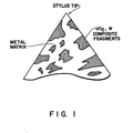
- the electrodes of the instant invention are formed from a blend mixture of two components, metal oxide-metal composite particles and metal powders.
- the composite particles typically contain between 10 6 and 5 x 10 7 aligned, submicron diameter, metallic fibers per cm2 uniformly embedded in an electrically insulating (oxide) matrix.
- the composite can be fabricated by well-known prior art techniques. One fabrication approach which can be utilized is described in detail in the publication "Report No. 6: Melt Grown Oxide-Metal Composites" from the School of Ceramic Engineering, Georgia Institute of Technology, A. T.
- the composite particles may be selected but not limited to systems such as U0 2 -W, Gd 2 0 3 (Ce0 2 )-Mo, Zr0 2 (Y 2 0 3 )-W, CeO 2 -Mo.
- the electrically conducting and connecting metal matrix may be composed but not limited to Cu, C o, or N i, or combinations of these metals.
- the reconstructed metal oxide-metal cermet is designated ROMC in the following description.
- the crushed and sized metal oxide-metal fragments are simply blended with desired amounts of metallic powder(s).
- the volume fraction of the composite particles may be between 10 and 80 percent ,more preferably between 15 and 75 percent, and most preferably between 25 and 60 percent.
- the composite metal powder mixture is compacted to consolidate the blend using pressure and/or temperature to form disc shaped material.
- the disc of the blend mixture is cut into square shaped bars which are subsequently machined into the desired cylindrical shaped electrodes.
- the composite blend mixture permits machining of the electrode into any desired shape by conventional machinery methods whereas conventional electrodes are formed by a more costly and complicated process.
- the first electrode is connected in series to a high voltage source which is disposed externally to the housing, by means of a first electrical lead wire extending through the bore of tube.
- the high voltage source is wired by means of a ground wire to a ground disposed externally to device.
- a second non- conductive (e.g. Lucite) elongated cylindrically shaped tube having a continuous bore therethraugh is disposed through aperture, wherein one end crf tube extends outwardly from housing and the other end of tube extends inwardly into a lower portion of oxide-metal chamber.
- a liquid-tight seal is formed between tube and sidewall by adhesive or other sealant means.
- a second electrode, or a series of second electrodes in parallel or in series, parallel combination are joined onto end of tube by suitable means such as an adhesive cement or the end of tube can be embedded in electrode.
- the second electrode is a planar shaped disc having at least one center longitudinally aligned aperture therethrough and optionally a plurality more of longitudinally aligned aperture therethrough at prescribed distances from the center aperture; alternately a plurality of longitudinally aligned apertures could be used arrayed symmetrically with respect to the center line with no aperture hole on the center line.
- the aperture holes could also be skewed to the center line.
- the second electrode 64 is disposed transversely within chamber below and spaced apart from the first electrode.
- Electrode can be moved longitudinally upward or downward thereby reducing or increasing the gap between the electrodes as well as modifying the flow of charge within the liquid.
- the second electrode is preferably formed from platinum, nickel or stainless and is wired in series to a high voltage resistor element disposed externally to housing by an electrical lead wire extending through tube.
- the resistor element is connected at its opposite end to ground juncture of the high voltage source.
- An external annularly shaped electrode e.g. stainless steel
- the center opening of electrode and discharge opening are aligned, wherein opening is preferably less than 2 cm in.
- electrode assists the spraying due to the development of the electrostatic field; however, the positioning of electrode at this position is not critical to operating as long as this electrode is disposed external to housing.
- the electrode is also connected to a second grounded junction disposed between ground and the first electrical juncture.
- the first electrode is negatively charged wherein the second electrode, has a relative positive potential with respect to the first electrode and the external electrode is at ground potential (the positive potential of source). In one mode of operation, the first electrode is negatively charged and the second electrode and the external electrode are relatively positively charged.
- the high voltage source which can be a direct voltage, an alternating voltage, or a pulsed voltage source of either polarity, wherein the source is 100 volts to 100 kilovolts, more preferably 100 volts to 50 kilovolts DC, and most preferably 100 volts to 30 kilovolts DC.
- the charge induced into the liquid within the chamber results in a flow from the first electrode to the second electrode.
- the liquid within the chamber flows towards the discharge opening of the base, wherein the electrical charge which is induced into the liquid within the chamber must be sufficient to generate excess free charge in the liquid within the chamber, wherein the charge can be positive or negative.
- the liquid is emitted outwardly therefrom in a spray configuration, (as a plurality of droplets) , wherein the external electrode enhances acceleration of the charged droplets.
- Example I describes the use of direct induction heating to form the cermet- type electrode
- Example II describes the hot-pressing of the composite-metal ROMC material in graphite dies
- Example III describes the direct bonding of the ROMC marerial on a metal pin during hot pressing.
Landscapes
- Powder Metallurgy (AREA)
- Electrostatic Spraying Apparatus (AREA)
- Physical Or Chemical Processes And Apparatus (AREA)
- Manufacture Of Alloys Or Alloy Compounds (AREA)
Applications Claiming Priority (2)
| Application Number | Priority Date | Filing Date | Title |
|---|---|---|---|
| US06/401,833 US4627903A (en) | 1982-07-26 | 1982-07-26 | Electrode for an electrostatic atomizing device |
| US401833 | 1982-07-26 |
Publications (3)
| Publication Number | Publication Date |
|---|---|
| EP0102735A2 true EP0102735A2 (de) | 1984-03-14 |
| EP0102735A3 EP0102735A3 (en) | 1985-06-12 |
| EP0102735B1 EP0102735B1 (de) | 1988-12-14 |
Family
ID=23589409
Family Applications (1)
| Application Number | Title | Priority Date | Filing Date |
|---|---|---|---|
| EP83304318A Expired EP0102735B1 (de) | 1982-07-26 | 1983-07-26 | Elektrode zur Erzeugung von Elektrostatischen Ladungen |
Country Status (5)
| Country | Link |
|---|---|
| US (1) | US4627903A (de) |
| EP (1) | EP0102735B1 (de) |
| JP (1) | JPS5941435A (de) |
| CA (1) | CA1223551A (de) |
| DE (1) | DE3378679D1 (de) |
Cited By (2)
| Publication number | Priority date | Publication date | Assignee | Title |
|---|---|---|---|---|
| EP0203694A3 (en) * | 1985-04-18 | 1987-01-07 | Nordson Corporation | Improved particle spray gun |
| US4819879A (en) * | 1985-10-25 | 1989-04-11 | Nordson Corporation | Particle spray gun |
Families Citing this family (31)
| Publication number | Priority date | Publication date | Assignee | Title |
|---|---|---|---|---|
| US4834939A (en) * | 1988-05-02 | 1989-05-30 | Hamilton Standard Controls, Inc. | Composite silver base electrical contact material |
| US5515681A (en) * | 1993-05-26 | 1996-05-14 | Simmonds Precision Engine Systems | Commonly housed electrostatic fuel atomizer and igniter apparatus for combustors |
| US5367869A (en) * | 1993-06-23 | 1994-11-29 | Simmonds Precision Engine Systems | Laser ignition methods and apparatus for combustors |
| DE19536604A1 (de) * | 1994-10-04 | 1996-04-11 | Simmonds Precision Engine Syst | Zündvorrichtung und Zündverfahren unter Verwendung elektrostatischer Düse und katalytischen Zünders |
| US20020031998A1 (en) * | 2000-08-23 | 2002-03-14 | Holland United Food Processing Equipment B.V. | Method of and device for processing poultry to be slaughtered |
| US8302887B2 (en) | 2005-03-31 | 2012-11-06 | Rain Bird Corporation | Drip emitter |
| US7648085B2 (en) * | 2006-02-22 | 2010-01-19 | Rain Bird Corporation | Drip emitter |
| JP4997800B2 (ja) * | 2006-03-16 | 2012-08-08 | 大日本印刷株式会社 | 金属酸化物膜の製造方法 |
| EP3326697A1 (de) | 2007-03-23 | 2018-05-30 | 3M Innovative Properties Company | Strömungsregler und verfahren für ein atemgerät |
| WO2008118768A1 (en) | 2007-03-23 | 2008-10-02 | 3M Innovative Properties Company | Air delivery apparatus for respirator hood |
| JP5474803B2 (ja) | 2007-10-05 | 2014-04-16 | スリーエム イノベイティブ プロパティズ カンパニー | レスピレーターの流量制御装置及び方法 |
| CN101909698B (zh) | 2007-11-12 | 2014-03-12 | 3M创新有限公司 | 具有空气流方向控制的呼吸器装置 |
| US8628032B2 (en) * | 2008-12-31 | 2014-01-14 | Rain Bird Corporation | Low flow irrigation emitter |
| US9877440B2 (en) | 2012-03-26 | 2018-01-30 | Rain Bird Corporation | Elastomeric emitter and methods relating to same |
| US20130248622A1 (en) | 2012-03-26 | 2013-09-26 | Jae Yung Kim | Drip line and emitter and methods relating to same |
| US10440903B2 (en) | 2012-03-26 | 2019-10-15 | Rain Bird Corporation | Drip line emitter and methods relating to same |
| US9485923B2 (en) | 2012-03-26 | 2016-11-08 | Rain Bird Corporation | Elastomeric emitter and methods relating to same |
| US9872444B2 (en) | 2013-03-15 | 2018-01-23 | Rain Bird Corporation | Drip emitter |
| JP5990118B2 (ja) * | 2013-03-15 | 2016-09-07 | 住友化学株式会社 | 静電噴霧装置、および静電噴霧装置の制御方法 |
| USD811179S1 (en) | 2013-08-12 | 2018-02-27 | Rain Bird Corporation | Emitter part |
| US10285342B2 (en) | 2013-08-12 | 2019-05-14 | Rain Bird Corporation | Elastomeric emitter and methods relating to same |
| US10631473B2 (en) | 2013-08-12 | 2020-04-28 | Rain Bird Corporation | Elastomeric emitter and methods relating to same |
| US9883640B2 (en) | 2013-10-22 | 2018-02-06 | Rain Bird Corporation | Methods and apparatus for transporting elastomeric emitters and/or manufacturing drip lines |
| US10330559B2 (en) | 2014-09-11 | 2019-06-25 | Rain Bird Corporation | Methods and apparatus for checking emitter bonds in an irrigation drip line |
| US10375904B2 (en) | 2016-07-18 | 2019-08-13 | Rain Bird Corporation | Emitter locating system and related methods |
| US11051466B2 (en) | 2017-01-27 | 2021-07-06 | Rain Bird Corporation | Pressure compensation members, emitters, drip line and methods relating to same |
| US10626998B2 (en) | 2017-05-15 | 2020-04-21 | Rain Bird Corporation | Drip emitter with check valve |
| USD883048S1 (en) | 2017-12-12 | 2020-05-05 | Rain Bird Corporation | Emitter part |
| US11985924B2 (en) | 2018-06-11 | 2024-05-21 | Rain Bird Corporation | Emitter outlet, emitter, drip line and methods relating to same |
| JP6782871B1 (ja) * | 2019-05-31 | 2020-11-11 | 花王株式会社 | 静電噴出装置 |
| US12207599B2 (en) | 2021-10-12 | 2025-01-28 | Rain Bird Corporation | Emitter coupler and irrigation system |
Family Cites Families (8)
| Publication number | Priority date | Publication date | Assignee | Title |
|---|---|---|---|---|
| US3729971A (en) * | 1971-03-24 | 1973-05-01 | Aluminum Co Of America | Method of hot compacting titanium powder |
| US3796673A (en) * | 1972-06-30 | 1974-03-12 | Atomic Energy Commission | Method of producing multicomponent metal-metal oxide single crystals |
| GB1505874A (en) * | 1975-08-06 | 1978-03-30 | Plessey Co Ltd | Electrically conductive composite materials |
| GB1571084A (en) * | 1975-12-09 | 1980-07-09 | Thorn Electrical Ind Ltd | Electric lamps and components and materials therefor |
| US4103063A (en) * | 1976-03-23 | 1978-07-25 | United Technologies Corporation | Ceramic-metallic eutectic structural material |
| US4255777A (en) * | 1977-11-21 | 1981-03-10 | Exxon Research & Engineering Co. | Electrostatic atomizing device |
| US4231796A (en) * | 1978-11-28 | 1980-11-04 | The United States Of America As Represented By The United States Department Of Energy | Internal zone growth method for producing metal oxide metal eutectic composites |
| US4386960A (en) * | 1980-10-06 | 1983-06-07 | General Electric Company | Electrode material for molten carbonate fuel cells |
-
1982
- 1982-07-26 US US06/401,833 patent/US4627903A/en not_active Expired - Lifetime
-
1983
- 1983-07-05 CA CA000431822A patent/CA1223551A/en not_active Expired
- 1983-07-26 DE DE8383304318T patent/DE3378679D1/de not_active Expired
- 1983-07-26 JP JP58136673A patent/JPS5941435A/ja active Granted
- 1983-07-26 EP EP83304318A patent/EP0102735B1/de not_active Expired
Cited By (2)
| Publication number | Priority date | Publication date | Assignee | Title |
|---|---|---|---|---|
| EP0203694A3 (en) * | 1985-04-18 | 1987-01-07 | Nordson Corporation | Improved particle spray gun |
| US4819879A (en) * | 1985-10-25 | 1989-04-11 | Nordson Corporation | Particle spray gun |
Also Published As
| Publication number | Publication date |
|---|---|
| US4627903A (en) | 1986-12-09 |
| JPH0453592B2 (de) | 1992-08-27 |
| EP0102735A3 (en) | 1985-06-12 |
| CA1223551A (en) | 1987-06-30 |
| EP0102735B1 (de) | 1988-12-14 |
| DE3378679D1 (en) | 1989-01-19 |
| JPS5941435A (ja) | 1984-03-07 |
Similar Documents
| Publication | Publication Date | Title |
|---|---|---|
| US4627903A (en) | Electrode for an electrostatic atomizing device | |
| US4084942A (en) | Ultrasharp diamond edges and points and method of making | |
| US4273561A (en) | Ultrasharp polycrystalline diamond edges, points, and improved diamond composites, and methods of making and irradiating same | |
| Yurlova et al. | Electric pulse consolidation: an alternative to spark plasma sintering | |
| Li et al. | EDM performance of TiC/copper-based sintered electrodes | |
| US4752713A (en) | Thermionic cathode of high emissive power for an electric tube, and process for its manufacture | |
| US5911919A (en) | Electron emission materials and components | |
| Green et al. | Osmium-tungsten alloys and their relevance to improved M-type cathodes | |
| RU2456369C1 (ru) | Способ формирования титан-бор-медных покрытий на медных контактных поверхностях | |
| Senthilnathan et al. | Synthesis of tungsten through spark plasma and conventional sintering processes | |
| RU2470089C1 (ru) | Способ формирования молибден-углерод-медных покрытий на медных контактных поверхностях | |
| US6190579B1 (en) | Electron emission materials and components | |
| US4638217A (en) | Fused metal ion source with sintered metal head | |
| JPH06287076A (ja) | 傾斜機能材の製造方法 | |
| Tucker et al. | A methodology for producing uniform distribution of UO2 in a tungsten matrix | |
| RU2680536C1 (ru) | Способ получения спеченного изделия из порошка кобальтохромового сплава | |
| US6051165A (en) | Electron emission materials and components | |
| JPH01156497A (ja) | 電着法による超電導性物品の形成方法 | |
| Grigoryev | High voltage electric discharge consolidation of tungsten carbide-cobalt powder | |
| Vaseekaran et al. | Single discharge, spark erosion in TiB2 and zinc part I: Experimental | |
| JP2688261B2 (ja) | 電界放出型イオン源 | |
| Yanagisawa et al. | Effect of direct current pulse discharge on electrical resistivity of copper and iron powder compacts | |
| JPH07278781A (ja) | 放電爆発コ−ティング方法 | |
| JP2000239709A (ja) | 直接通電焼結法および焼結装置 | |
| Husmann et al. | Characteristics of porous tungsten ionizers |
Legal Events
| Date | Code | Title | Description |
|---|---|---|---|
| PUAI | Public reference made under article 153(3) epc to a published international application that has entered the european phase |
Free format text: ORIGINAL CODE: 0009012 |
|
| AK | Designated contracting states |
Designated state(s): BE DE FR GB IT NL |
|
| PUAL | Search report despatched |
Free format text: ORIGINAL CODE: 0009013 |
|
| AK | Designated contracting states |
Designated state(s): BE DE FR GB IT NL |
|
| 17P | Request for examination filed |
Effective date: 19851113 |
|
| 17Q | First examination report despatched |
Effective date: 19861126 |
|
| R17C | First examination report despatched (corrected) |
Effective date: 19870626 |
|
| GRAA | (expected) grant |
Free format text: ORIGINAL CODE: 0009210 |
|
| AK | Designated contracting states |
Kind code of ref document: B1 Designated state(s): BE DE FR GB IT NL |
|
| ITF | It: translation for a ep patent filed | ||
| REF | Corresponds to: |
Ref document number: 3378679 Country of ref document: DE Date of ref document: 19890119 |
|
| ET | Fr: translation filed | ||
| PLBE | No opposition filed within time limit |
Free format text: ORIGINAL CODE: 0009261 |
|
| STAA | Information on the status of an ep patent application or granted ep patent |
Free format text: STATUS: NO OPPOSITION FILED WITHIN TIME LIMIT |
|
| 26N | No opposition filed | ||
| ITTA | It: last paid annual fee | ||
| REG | Reference to a national code |
Ref country code: GB Ref legal event code: IF02 |
|
| PGFP | Annual fee paid to national office [announced via postgrant information from national office to epo] |
Ref country code: GB Payment date: 20020613 Year of fee payment: 20 |
|
| PGFP | Annual fee paid to national office [announced via postgrant information from national office to epo] |
Ref country code: NL Payment date: 20020618 Year of fee payment: 20 |
|
| PGFP | Annual fee paid to national office [announced via postgrant information from national office to epo] |
Ref country code: FR Payment date: 20020702 Year of fee payment: 20 |
|
| PGFP | Annual fee paid to national office [announced via postgrant information from national office to epo] |
Ref country code: DE Payment date: 20020731 Year of fee payment: 20 |
|
| PGFP | Annual fee paid to national office [announced via postgrant information from national office to epo] |
Ref country code: BE Payment date: 20020910 Year of fee payment: 20 |
|
| PG25 | Lapsed in a contracting state [announced via postgrant information from national office to epo] |
Ref country code: GB Free format text: LAPSE BECAUSE OF EXPIRATION OF PROTECTION Effective date: 20030725 |
|
| PG25 | Lapsed in a contracting state [announced via postgrant information from national office to epo] |
Ref country code: NL Free format text: LAPSE BECAUSE OF EXPIRATION OF PROTECTION Effective date: 20030726 |
|
| REG | Reference to a national code |
Ref country code: GB Ref legal event code: PE20 |
|
| NLV7 | Nl: ceased due to reaching the maximum lifetime of a patent |
Effective date: 20030726 |