EP0102805B1 - Werkstückhaltevorrichtung - Google Patents
Werkstückhaltevorrichtung Download PDFInfo
- Publication number
- EP0102805B1 EP0102805B1 EP83304876A EP83304876A EP0102805B1 EP 0102805 B1 EP0102805 B1 EP 0102805B1 EP 83304876 A EP83304876 A EP 83304876A EP 83304876 A EP83304876 A EP 83304876A EP 0102805 B1 EP0102805 B1 EP 0102805B1
- Authority
- EP
- European Patent Office
- Prior art keywords
- work holding
- chuck
- holding device
- slip ring
- seals
- Prior art date
- Legal status (The legal status is an assumption and is not a legal conclusion. Google has not performed a legal analysis and makes no representation as to the accuracy of the status listed.)
- Expired
Links
- 238000007789 sealing Methods 0.000 claims description 16
- 239000012530 fluid Substances 0.000 claims description 14
- 230000005540 biological transmission Effects 0.000 claims description 3
- 230000004323 axial length Effects 0.000 description 1
- 238000010438 heat treatment Methods 0.000 description 1
- 239000002184 metal Substances 0.000 description 1
Images


Classifications
-
- B—PERFORMING OPERATIONS; TRANSPORTING
- B23—MACHINE TOOLS; METAL-WORKING NOT OTHERWISE PROVIDED FOR
- B23B—TURNING; BORING
- B23B31/00—Chucks; Expansion mandrels; Adaptations thereof for remote control
- B23B31/02—Chucks
- B23B31/24—Chucks characterised by features relating primarily to remote control of the gripping means
- B23B31/30—Chucks characterised by features relating primarily to remote control of the gripping means using fluid-pressure means in the chuck
- B23B31/302—Hydraulic equipment, e.g. pistons, valves, rotary joints
Definitions
- the invention relates to work holding devices such as chucks.
- Rotatable work holding devices such as chucks are known which are operated by fluid pressure which is supplied to a stationary slip ring.
- fluid pressure which is supplied to a stationary slip ring.
- Sealing means must be provided between the slip ring and the work holding device.
- the sealing means must not remain in contact with the work holding device once the device has been caused to grip a workpiece and starts to rotate, otherwise the sealing means would burn out.
- the sealing means is therefore normally biased out of contact with the work holding device and is arranged so that when fluid pressure is applied to the slip ring for transmission to the work holding device part of the fluid forces the sealing means against the work holding device.
- DE-C-963 288 shows an arrangement in which the sealing means is operated by the main fluid pressure but a fluid flow passage is needed through the sealing means and the actuation of the sealing means is not very positive.
- the invention provides a rotatable work holding device comprising a chuck body having passage means for transmission of fluid pressure to operate the work holding device, a slip ring for the distribution of fluid pressure to the passage means, and sealing means between the slip ring and the work holding device, characterised in that, in addition to first passage means for operating the work holding device, there is second passage means for operating the seals, such that a negative pressure is applied therethrough to retract the seals out of contact with the chuck body and a positive pressure is applied to force the seals against the chuck body, the first and second passage means being separate and distinct from each other and having respective separate and distinct inlets.
- the provisions of separate and district passage means to operate the sealing means makes it possible to use sealing means without a passage therethrough and to achieve more positive actuation of the seal.
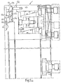
- the chuck illustrated in the Figures comprises a generally cylindrical body 10 which may be mounted on a spindle of a machine tool for rotation at high speed.
- the mechanism for gripping a workpiece in the chuck does not comprise part of the present invention and will not be described in detail. It is however described in our co-pending European application No. 0102236 of even date.
- the present invention is concerned with a stationary slip ring 17 which surrounds the body of the chuck.
- the slip ring 17 is recessed radially inwardly as is evident from Figures 1a and 1b.
- the ring is supported on the chuck body by means of three bearings spaced apart equally in the circumferential direction, one of the bearings being illustrated at 40 in Figure 2.
- Each bearing comprises a cam follower in the form of a roller 41 which runs on bearings 42 on a spindle 43 fixed to the ring 17.
- Each wheel 41 engages in a track 44 extending around the periphery of a part 45 of the chuck body.
- Recessed into the slip ring 17 are two anular compressed air distribution passages 46 and 47.
- air can be supplied to passage 46 through an inlet 16. Air can also be supplied when necessary, through a similar inlet arranged at a different circumferential location, through the passage 47.
- control means When it is desired to apply fluid pressure to the chuck to open or close the jaws, control means (not shown) are operated.
- An electric pick-up 49 (shown at the foot of Figure 2) is mounted in the slip ring and is sensitive to the passage of holes provided in the body of the chuck. If the pick-up fails to detect the presence of a hole within a given period of time then this indicates that the chuck is stationary and that it is safe to operate the chuck.
- the control means then applies fluid pressure through an inlet 50 shown in Figure 3.
- the inlet 50 has three branches 51 which communicate with the bottom of the recesses housing the seals 48. Thus fluid pressure forces the seals 48 against the body of the chuck.
- Fluid pressure can then be applied to the passage 46 or passage 47, as desired, to operate the chuck, for example as described in our co-pending Patent Application No. 0102236 of even date.
- the means to apply suction is not critical to the invention and many for example comprise a vacuum pump or a venturi device.
- the engagement of the wheels 41 in the track 44 may be insufficient to resist this tendency for movement without causing damage to the bearings 42.
- Three abutment devices are therefore provided, equally spaced apart around the periphery of the chuck, each abutment device lying between two of the bearings 40.
- One of the abutment devices 52 is shown in Figure 1a.
- the abutment device 52 comprises a metal block 53 which fits within a recess provided in the slip ring and is clamped against the slip ring by a cover plate 54 which is fastened over the recess by bolts (not shown).
- a pin 55 secured to the cover plate engages in an aperture in the block 53 to prevent radial movement of the block 53.
- the block 53 has an abutment face 56 which is ground down so that when the chuck is in use it is just clear of the left-hand radially extending face of the track 44. This is to avoid undesirable rubbing contact between the block 53 and the body of the chuck during rotation of the chuck.
- abutment blocks 53 instead of using the abutment blocks 53, studs or other abutment devices could be provided which project axially from the slip ring 17 to abut against the headstock or other part of the machine tool to which the chuck is to be fitted.
- the axial length of these devices could be adjustable.
- the slip ring 17 may be provided with a continuous flange-like abutment ring which engages with part of the chuck body.
- the recesses which house the 0-ring seals 48 may be inclined slightly to the axial direction, so that the bottom of each recess lies slightly nearer to the centre of the chuck than the mouth of the recess. With such an arrangement the resilience of the seals may tend to bias them into the bottom of the recesses, i.e. away from the body of the chuck.
Landscapes
- Engineering & Computer Science (AREA)
- Mechanical Engineering (AREA)
- Gripping On Spindles (AREA)
Claims (3)
Applications Claiming Priority (2)
| Application Number | Priority Date | Filing Date | Title |
|---|---|---|---|
| GB8224770 | 1982-08-28 | ||
| GB8224770 | 1982-08-28 |
Publications (3)
| Publication Number | Publication Date |
|---|---|
| EP0102805A2 EP0102805A2 (de) | 1984-03-14 |
| EP0102805A3 EP0102805A3 (en) | 1985-06-05 |
| EP0102805B1 true EP0102805B1 (de) | 1988-10-12 |
Family
ID=10532593
Family Applications (1)
| Application Number | Title | Priority Date | Filing Date |
|---|---|---|---|
| EP83304876A Expired EP0102805B1 (de) | 1982-08-28 | 1983-08-24 | Werkstückhaltevorrichtung |
Country Status (2)
| Country | Link |
|---|---|
| EP (1) | EP0102805B1 (de) |
| DE (1) | DE3378195D1 (de) |
Families Citing this family (2)
| Publication number | Priority date | Publication date | Assignee | Title |
|---|---|---|---|---|
| DE3674712D1 (de) * | 1985-10-23 | 1990-11-08 | Aced Sa | Drehender hydraulikzylinder. |
| PL3444056T3 (pl) * | 2017-08-14 | 2020-05-18 | Hsuan-Lung Wu | Hydrauliczny uchwyt |
Citations (1)
| Publication number | Priority date | Publication date | Assignee | Title |
|---|---|---|---|---|
| DE963288C (de) * | 1954-12-12 | 1957-05-02 | Forkardt Paul Kg | Rotierender Zylinder fuer druckluftbetaetigte Spannfutter an Werkzeugmaschinen |
Family Cites Families (3)
| Publication number | Priority date | Publication date | Assignee | Title |
|---|---|---|---|---|
| CH223584A (de) * | 1941-03-20 | 1942-09-30 | Pittler Werkzeugmaschinenfab | Fettpolsterabdichtung an Druckluftzuführungseinrichtungen für umlaufende Spannfutter oder dergleichen von Werkzeugmaschinen. |
| DE1777371C3 (de) * | 1967-09-09 | 1980-05-08 | Smw Schneider & Weisshaupt Gmbh, 7996 Meckenbeuren | Druckmittelzuführung für Spannfutter bzw. Spannzylinder |
| DE2546746C2 (de) * | 1975-10-18 | 1983-01-13 | SMW Schneider & Weißhaupt GmbH, 7996 Meckenbeuren | Einrichtung zur Zuführung von Druckmittel in ein umlaufendes Gehäuseteil |
-
1983
- 1983-08-24 EP EP83304876A patent/EP0102805B1/de not_active Expired
- 1983-08-24 DE DE8383304876T patent/DE3378195D1/de not_active Expired
Patent Citations (1)
| Publication number | Priority date | Publication date | Assignee | Title |
|---|---|---|---|---|
| DE963288C (de) * | 1954-12-12 | 1957-05-02 | Forkardt Paul Kg | Rotierender Zylinder fuer druckluftbetaetigte Spannfutter an Werkzeugmaschinen |
Also Published As
| Publication number | Publication date |
|---|---|
| DE3378195D1 (en) | 1988-11-17 |
| EP0102805A2 (de) | 1984-03-14 |
| EP0102805A3 (en) | 1985-06-05 |
Similar Documents
| Publication | Publication Date | Title |
|---|---|---|
| US2568092A (en) | Swivel connection for air operated chucks | |
| AU1753283A (en) | Seal for rotary fluid machine | |
| MY123697A (en) | Snug fitting apparatus for tire assembly | |
| CN117558672B (zh) | 用于晶圆检测的承载设备 | |
| GB1273638A (en) | Centrifuge chuck | |
| US3975030A (en) | Chuck with dual independently actuable sets of jaws | |
| EP0102805B1 (de) | Werkstückhaltevorrichtung | |
| US3954275A (en) | Machine tool chucks | |
| US4349207A (en) | Fluid actuated chuck | |
| US2597280A (en) | Power-operated universal chuck | |
| CN117532033B (zh) | 一种自制动定心卡盘 | |
| US3344695A (en) | Floating work driver chuck | |
| US3945275A (en) | Rotary jaw chuck with stock detector | |
| US4621568A (en) | Rotary hydraulic cylinder | |
| US4312155A (en) | Apparatus for grinding grooves in the inner race of a constant velocity universal joint | |
| EP0102236B1 (de) | Spannfutter | |
| US2843389A (en) | Chuck | |
| US3468552A (en) | Machine tool spindle and workholder actuating mechanism | |
| JP3082022B2 (ja) | 工作機械用エアーチャック | |
| US3881604A (en) | Machine loader pickup device | |
| JPH0713943Y2 (ja) | モータのブレーキ装置 | |
| GB1504296A (en) | Work holding chucks for machine tools | |
| JPH0426197Y2 (de) | ||
| US2833543A (en) | Fluid operated chuck | |
| JPS5940603Y2 (ja) | 回転する操作用シリンダへの圧力媒体供給装置 |
Legal Events
| Date | Code | Title | Description |
|---|---|---|---|
| PUAI | Public reference made under article 153(3) epc to a published international application that has entered the european phase |
Free format text: ORIGINAL CODE: 0009012 |
|
| AK | Designated contracting states |
Designated state(s): DE FR GB IT |
|
| PUAL | Search report despatched |
Free format text: ORIGINAL CODE: 0009013 |
|
| AK | Designated contracting states |
Designated state(s): DE FR GB IT |
|
| 17P | Request for examination filed |
Effective date: 19851009 |
|
| 17Q | First examination report despatched |
Effective date: 19870204 |
|
| GRAA | (expected) grant |
Free format text: ORIGINAL CODE: 0009210 |
|
| AK | Designated contracting states |
Kind code of ref document: B1 Designated state(s): DE FR GB IT |
|
| REF | Corresponds to: |
Ref document number: 3378195 Country of ref document: DE Date of ref document: 19881117 |
|
| ET | Fr: translation filed | ||
| ITF | It: translation for a ep patent filed | ||
| PLBE | No opposition filed within time limit |
Free format text: ORIGINAL CODE: 0009261 |
|
| STAA | Information on the status of an ep patent application or granted ep patent |
Free format text: STATUS: NO OPPOSITION FILED WITHIN TIME LIMIT |
|
| 26N | No opposition filed | ||
| PGFP | Annual fee paid to national office [announced via postgrant information from national office to epo] |
Ref country code: FR Payment date: 19900829 Year of fee payment: 8 |
|
| ITTA | It: last paid annual fee | ||
| PGFP | Annual fee paid to national office [announced via postgrant information from national office to epo] |
Ref country code: DE Payment date: 19901006 Year of fee payment: 8 |
|
| PGFP | Annual fee paid to national office [announced via postgrant information from national office to epo] |
Ref country code: GB Payment date: 19910731 Year of fee payment: 9 |
|
| PG25 | Lapsed in a contracting state [announced via postgrant information from national office to epo] |
Ref country code: FR Effective date: 19920430 |
|
| PG25 | Lapsed in a contracting state [announced via postgrant information from national office to epo] |
Ref country code: DE Effective date: 19920501 |
|
| REG | Reference to a national code |
Ref country code: FR Ref legal event code: ST |
|
| PG25 | Lapsed in a contracting state [announced via postgrant information from national office to epo] |
Ref country code: GB Effective date: 19920824 |
|
| GBPC | Gb: european patent ceased through non-payment of renewal fee |
Effective date: 19920824 |