EP0102824A2 - Pompe électromagnétique à basse puissance - Google Patents
Pompe électromagnétique à basse puissance Download PDFInfo
- Publication number
- EP0102824A2 EP0102824A2 EP83305009A EP83305009A EP0102824A2 EP 0102824 A2 EP0102824 A2 EP 0102824A2 EP 83305009 A EP83305009 A EP 83305009A EP 83305009 A EP83305009 A EP 83305009A EP 0102824 A2 EP0102824 A2 EP 0102824A2
- Authority
- EP
- European Patent Office
- Prior art keywords
- armature
- fluid
- housing
- electromagnet
- outlet
- Prior art date
- Legal status (The legal status is an assumption and is not a legal conclusion. Google has not performed a legal analysis and makes no representation as to the accuracy of the status listed.)
- Granted
Links
Images



Classifications
-
- A—HUMAN NECESSITIES
- A61—MEDICAL OR VETERINARY SCIENCE; HYGIENE
- A61M—DEVICES FOR INTRODUCING MEDIA INTO, OR ONTO, THE BODY; DEVICES FOR TRANSDUCING BODY MEDIA OR FOR TAKING MEDIA FROM THE BODY; DEVICES FOR PRODUCING OR ENDING SLEEP OR STUPOR
- A61M5/00—Devices for bringing media into the body in a subcutaneous, intra-vascular or intramuscular way; Accessories therefor, e.g. filling or cleaning devices, arm-rests
- A61M5/14—Infusion devices, e.g. infusing by gravity; Blood infusion; Accessories therefor
- A61M5/142—Pressure infusion, e.g. using pumps
- A61M5/14244—Pressure infusion, e.g. using pumps adapted to be carried by the patient, e.g. portable on the body
- A61M5/14276—Pressure infusion, e.g. using pumps adapted to be carried by the patient, e.g. portable on the body specially adapted for implantation
-
- A—HUMAN NECESSITIES
- A61—MEDICAL OR VETERINARY SCIENCE; HYGIENE
- A61M—DEVICES FOR INTRODUCING MEDIA INTO, OR ONTO, THE BODY; DEVICES FOR TRANSDUCING BODY MEDIA OR FOR TAKING MEDIA FROM THE BODY; DEVICES FOR PRODUCING OR ENDING SLEEP OR STUPOR
- A61M5/00—Devices for bringing media into the body in a subcutaneous, intra-vascular or intramuscular way; Accessories therefor, e.g. filling or cleaning devices, arm-rests
- A61M5/14—Infusion devices, e.g. infusing by gravity; Blood infusion; Accessories therefor
- A61M5/142—Pressure infusion, e.g. using pumps
- A61M5/14212—Pumping with an aspiration and an expulsion action
- A61M5/14216—Reciprocating piston type
-
- F—MECHANICAL ENGINEERING; LIGHTING; HEATING; WEAPONS; BLASTING
- F04—POSITIVE - DISPLACEMENT MACHINES FOR LIQUIDS; PUMPS FOR LIQUIDS OR ELASTIC FLUIDS
- F04B—POSITIVE-DISPLACEMENT MACHINES FOR LIQUIDS; PUMPS
- F04B17/00—Pumps characterised by combination with, or adaptation to, specific driving engines or motors
- F04B17/03—Pumps characterised by combination with, or adaptation to, specific driving engines or motors driven by electric motors
- F04B17/04—Pumps characterised by combination with, or adaptation to, specific driving engines or motors driven by electric motors using solenoids
- F04B17/042—Pumps characterised by combination with, or adaptation to, specific driving engines or motors driven by electric motors using solenoids the solenoid motor being separated from the fluid flow
-
- F—MECHANICAL ENGINEERING; LIGHTING; HEATING; WEAPONS; BLASTING
- F04—POSITIVE - DISPLACEMENT MACHINES FOR LIQUIDS; PUMPS FOR LIQUIDS OR ELASTIC FLUIDS
- F04B—POSITIVE-DISPLACEMENT MACHINES FOR LIQUIDS; PUMPS
- F04B3/00—Machines or pumps with pistons coacting within one cylinder, e.g. multi-stage
-
- F—MECHANICAL ENGINEERING; LIGHTING; HEATING; WEAPONS; BLASTING
- F04—POSITIVE - DISPLACEMENT MACHINES FOR LIQUIDS; PUMPS FOR LIQUIDS OR ELASTIC FLUIDS
- F04B—POSITIVE-DISPLACEMENT MACHINES FOR LIQUIDS; PUMPS
- F04B53/00—Component parts, details or accessories not provided for in, or of interest apart from, groups F04B1/00 - F04B23/00 or F04B39/00 - F04B47/00
- F04B53/008—Spacing or clearance between cylinder and piston
Definitions
- This invention relates to the art of electromagnetically-operated fluid pumps, and more particularly to a new and improved electromagnetic pump which operates at extremely low power.
- One area of use of the present invention is implantable drug delivery systems, although the principles of the present invention can be variously applied.
- the principal requirements for a pump in such applications are low power drain, since the pump must be driven by an implanted battery, and compatibility with the drug being pumped.
- Other important requirements are that the pump be relatively insensitive to the presence of bubbles in the fluid being handled, be relatively easy to prime, and provide an adequate fluid pressure increase across the pump which is sufficient for the intended uses of the pump.
- a further requirement is to have low pressure drop across the pump check valve while at the same time providing satisfactory long term sealing against back flow.
- the present invention provides an electromagnetic pump comprising a housing having fluid receiving and pumping chambers therein and in communication with an inlet and an outlet, respectively, electromagnet means carried by the housing located external to the fluid chambers thereof, and barrier means in the form of a thin diaphragm of fluid impermeable material which hermetically isolates the electromagnet from the fluid chamber.
- An armature in the housing is movable within a body of magnetically permeable material and has a pole portion located for magnetic attraction by the electromagnet and has a plunger portion in the pumping chamber for forcing fluid out of the chamber through the outlet.
- the armature is moved from a rest position through a forward pumping stroke when attracted by the electromagnet means to force fluid out of the pumping chamber through the outlet, and the armature is moved by biasing means in an opposite direction through a return stroke back to the rest position.
- a magnetic circuit is defined including the electromagnet means, a portion of the fluid-impermeable barrier, the body, the armature pole portion and a gap defined between the pole portion and the electromagnet which gap is closed during movement of the armature toward the electromagnet during energization thereof.
- the pump is made electrically and magnetically efficient by minimizing the total gap within the magnetic circuit, by having the pole face area relatively large on the armature pole portion, and by having the electromagnet include a coil or a core of relatively small diameter.
- a pump check valve can be provided separately or incorporated integrally with the armature in the form of a valve member movably carried by the armature and positioned for closing the pump inlet when the armature is in the rest position and opening the inlet after the armature begins the forward pumping stroke.
- the pump includes a pair of serially-connected fluid pumping chambers, one in communication with the fluid receiving chamber and the other in communication with the outlet, and the armature has first and second plunger portions in respective ones of the pumping chambers for forcing fluid out of the chambers and through the outlet.
- the armature forces fluid from one pumping chamber to the other and then out of that chamber through the outlet.
- a pump check valve is within the pump and associated with the armature in the form of a valve member located in the fluid receiving chamber, movably carried by the armature, and positioned for closing the pump inlet when the armature is in the rest position and opening the inlet after the armature begins the fowward pumping stroke.
- the arrangement is such that the volume of the fluid receiving chamber is minimized in the region between the check valve and the neighboring one of the armature plunger portions. Long term sealing against back flow is provided by a relatively stronger biasing means, and short term sealing by a relatively weaker biasing means.
- a pump 10 includes a housing 12 which is generally hollow cylindrical in overall shape and includes an interior region for containing fluid, i.e. the liquid to be pumped. As shown in Fig. 2, the hollow interior region is divided in a manner which will be described into a fluid receiving chamber 14 and a fluid pumping chamber 16 in fluid communication therewith. There is an inlet generally designated 18 in fluid communication with the receiving chamber 14 and adapted to be connected to a source or supply of fluid to be pumped. There is also an outlet 20 in fluid communication with the pumping chamber 16 and adapted to be in fluid communication with a location to which the fluid is to be pumped.
- check valve means operatively associated with the fluid containing region of pump 10 for allowing fluid flow in a direction from the inlet 18 through outlet 20 and blocking fluid flow in a direction from the outlet through the inlet.
- a check valve 22 is connected between outlet 20 and a conduit 24 for supplying pumped fluid to a location of use.
- housing 12 is generally hollow cylindrical in overall shape including a central body portion 28 of relatively substantial wall thickness. Housing 12 also includes a first axial end portion 30 extending from one end of body portion 28, i.e. the right-hand end as viewed in Fig. 2, and which is of relatively smaller wall thickness. Portions 28 and 30 define the interior region of constant diameter having an inner surface 32. Thus, the outer surfaces of portions 28 and 30 are of different diameters and meet in an annular surface 34.
- the housing 12 has a second axial end portion 38 extending from the other end of body 28, i.e. the left-hand end as viewed in Fig. 2, which also is of smaller wall thickness. End portion 38 has a relatively larger diameter inner wall surface 40 which meets surface 32 in annular intermediate wall 42.
- Body portion 28 is provided with a longitudinal bore or passage 44 for placing pumping chamber 16 in fluid communication with outlet 20.
- Outlet 20 is located on the side of housing 12 for communication with the passage 44.
- Housing portion- 28 is provided with a radially extending opening in the outer wall thereof in communication with passage 44. The opening is formed to include an annular recess 50 defining a ledge which engages an annular rim 52 of a tubular fitting which defines the outlet 20.
- Inlet 18 is provided by a plug-like element which is fitted into the open end of the housing axial end portion 30.
- the element includes a main body 56 generally cylindrical in shape and having an outer diameter substantially equal to the diameter of inner wall surface 32 thereby providing a close fit therein.
- Body 56 has one axial end face 58 located in chamber 14, and adjacent the opposite end face the outer surface of body 56 is provided with an annular rim 60 which abuts the annular end face of housing portion 30 for placement and securement of the fitting in the housing. The two components are secured together by welding or other suitable means.
- the body portion 56 has an internal wall surface 62 defining a region of substantial diameter.
- the inlet portion 18 is defined by a relatively smaller diameter portion of the plug element having an internal passage 64 of relatively smaller diameter compared to passage 62.
- Inlet 18 is adapted for connection to a conduit such as a flexible tubing leading from a source or supply of fluid to be pumped.
- housing 12 and the inlet and outlet fittings 18 and 20, respectively, all are of metal, and for a drug delivery pump for implantation in a patient, titanium has been found to provide satisfactory results.
- housing 12 has an overall ' length of about 0.425 inch measured between the axial end faces of portions 30 and 38.
- Surface 32 has a diameter of about 0.15 inch, and the axial end face of portion 30 has a radial dimension of about 0.03 inch.
- Surface 40 has a diameter of about 0.26 inch, and the axial end face of housing portion 38 has a radial thickness of about 0.02 inch.
- Passage 44 in housing body 28 and the interior passage in outlet fitting 20 both have a diameter of about 0.032 inch.
- the passage 62 has a diameter of about 0.073 inch
- passage 64 has a diameter of about 0.032 inch.
- the pump of the present invention further comprises electromagnet means generally designated 70 carried by housing 12 and located external to the fluid containing region of the housing.
- the electromagnet 70 includes a core 72 in the form of a spool which is generally solid cylindrical in shape.
- a coil 74 is wound on spool 72 and contained within a hollow housing 76 generally cylindrical in shape.
- One end of electromagnet 70 is adjacent and in abutting relation to housing 12, and the opposite end, i.e. the left-hand end as viewed in Fig. 2, is closed by a plate element 78 fitted within the open end of housing 76 and fitted onto an end of spool 72.
- Electromagnet 70 is joined to housing 12 in the following manner.
- the interior, fluid containing region of housing 12 and the electromagnet 70 are separated by a barrier means of fluid impervious material in the form of a relatively thin plate or diaphragm-like component 80.
- the end of magnet housing 76 adjacent housing 12 is provided with an annular band 82 around the outer surface and adjacent the axial end face of housing 76.
- the outer diameter of band 82 when placed on housing 76 is substantially equal to the outer diameter of housing portion 38 so that the respective outer surfaces are substantially flush.
- the axial end faces of band 82 and magnet housing 76 are coplanar.
- the housing and electromagnet structures are placed in abutting relation on opposite surface portions of the plate 80, and the assembly secured together by a weld joining the respective adjacent outer surfaces of band 82 and housing portion 38.
- an enlarged annular end portion 84 of spool 72 contacts the central portion of plate 80 in a manner supporting the same.
- spool 72, magnet housing 76 and closure 78 are of ferromagnetic material, for example 0.4750 nickel iron alloy.
- Plate 80 and band 82 are of titanium, the material of plate 80 being found suitable for use in the exemplary implanted drug delivery pump previously mentioned.
- Spool 72 has a length of about 0.555 inch and a diameter of 0.079 inch.
- Housing 76 has a wall thickness of about 0.03 inch, band 82 a i thickness of about 0.02 inch and diaphragm 80 a thickness of about 0.001 inch.
- Coil 74 has about 3600 turns of 42 gauge wire.
- the pump of the present invention further comprises a body 90 of magnetically permeable material in the fluid containing region of housing 12 and between the fluid receiving chamber 14 and the fluid pumping chamber 16.
- body 90 also defines a portion of the magnetic circuit in the pump, along with other components of the pump, in a manner which will be described.
- Body 90 is generally solid cylindrical in shape having an outer diameter substantially equal to the diameter of housing inner surface 40 thereby providing a close fitting relationship.
- Body 90 has a main body portion between axial end surfaces 92 and 94 which is of an axial length less than the distance between housing surface 42 and plate 80 by an amount determined by the desired dimension of pumping chamber 16.
- Body 90 is formed to include an outer annular rim portion 96 extending from end face 92 and which abuts a corresponding surface portion of plate 80 as shown in Fig. 2.
- the radial thickness of rim portion 96 is substantially equal to that of magnet housing 76, and the two are in substantial alignment for maximizing transmission of magnetic flux therebetween in a manner which will be described.
- Body 90 is provided with a central through bore or passage 98 of substnatial diameter for receiving a portion of the pump armature in a manner which will be described.
- the main portion of body 90 also is provided with a smaller through bore or passage 100 offset from passage 98 and of substantially the same diameter and in registry with outlet passage 44 thereby providing fluid communication between pumping chamber 16 and the outlet 20.
- Body 90 is positioned in housing 12 by means of a rod 102 extending through corresponding bores in body 90 and valve housing portion 28 shown in Fig. 2, the rod 102 preferably being of Teflon material and the parts being secured together by a compression fit.
- body 90 is of mu metal which is selected to provide the desired degree of magnetic permeability while at the same time being compatible with medicine or the like for use in the exwmplary implanted drug delivery pump previously mentioned.
- mu metal includes nickel in a major portion with the balance including iron, copper and chromium.
- some or all of the external surfaces of body 90 can be plated or coated with gold or other suitable material chose to enhance the compatibility of the drug with the external surface.
- the outer diameter of body 90 is about 0.26 inch, the axial length between end face 94 and the end face of rim 96 is about 0.130 inch, and the axial length between end faces 92,94 is about 0.1 inch.
- Passage 100 has a diameter of about 0.029 inch and the central passage 98 a diameter of about 0.1 inch.
- the pump according to the present invention further comprises an armature generally designated 110 positioned in the fluid containing region of housing 12.
- the armature has a pole portion located for magnetic attraction by the electromagnet 70 and has a plunger portion in the pumping chamber 16 for forcing fluid outof the chamber and outlet 20.
- the armature 110 is movably supported in housing 12 for movement from a rest position through a forward pumping stroke when attracted by the electromagnet 70 to force fluid out of the pumping chamber 16 through outlet 20, and for movement in an opposite direction through a return stroke back to the rest position.
- armature 110 is shown in a position at the end of the forward pumping stroke in response to energization of electromagnet 70
- Fig. 3 armature 110 is shown in the rest position at the end of the return stroke which will be described in detail presently.
- Armature 110 includes a shaft or rod portion 112 which is positioned in housing 12 with the longit- tudinal axis thereof generally coincident with the longitudinal axis of housing 12. A major portion of the length is a section of relatively small diameter.
- the armature further includes an enlarged body portion 114 of magnetically permeable material which provides the armature pole portion and the plunger portion in a manner which will be described.
- Body 114 is solid cylindrical in shape having an outer diameter slightly smaller than the diameter of passage 98 in body 90. This is to allow reciprocal movement of armature body 114 within the body 90 during the foward and return strokes of armature 110.
- the sizes of the outer diameter of body 114 and the diameter of passage 98 are selected to provide a fluid leakage path from pumping chamber 16 to receiving chamber 14 during the armature return stroke in a manner which will be described.
- the armature body 114 terminates at the end facing electromagnet 70 in an axial end face 116 which serves as the pole face and is disposed substantially perpendicular to the armature axis.
- the pole face 116 together with electromagnet 70 define the magnetic circuit gap which is closed during the forward pumping stroke.
- the pole face 116 is of relatively large cross-sectional area as compared to the cross sectional area of the armature shaft portion 112.
- the body 114 also serves as the plunger portion of the armature because as the pole face 116 moves toward plate 80 during the forward stroke when magnet 70 is energized, body 114, upon moving into pumping chamber 116 displaces fluid therefrom forcing it out through passages 100,44 to outlet 20.
- Shaft portion 112 is fixed to body 114 in the following manner.
- Body 114 is provided with a longitudinal bore extending inwardly from the opposite axial end face 118 which terminates within body 114 at a location spaced from pole face 116.
- a sleeve 120 of fluoropolymer material such as Teflon is fitted in the bore, and the end of the armature shaft portion 112 is fixed in the sleeve or bushing 120.
- the foregoing is provided by a mechanical compression fit.
- Armature 110 includes two relatively larger diameter shaft sections spaced axially from body 114 in a direction opposite therefrom.
- first section 124 facing body 114
- second, axially adjacent section 126 which of slightly larger diameter.
- the two sections 124,126 are of relatively short axial length, and they define therebetween an annular shoulder facing the body 114.
- biasing means in the form of a coil spring 130 for urging armature 110 toward the rest position shown in Fig. 3.
- One end of spring 130 seats in the annular shoulder defined by the armature shaft sections 124,126.
- the opposite end of spring 130 seats in an annular spring retainer element 134 which has an annular rim portion which abuts against the end face 94 of body 90 as shown in Fig. 2.
- the annular shape of retainer 134 with the two diameter rim sections, enables it to be located concentric with the armature shaft section 112 to receive the spring 130 which also is concentric with the shaft, while at the same time not interfering with body 114 during movement of the armature 110.
- the outer diameter of the largest rim portion of retainer 134 is substantially equal to the diameter of surface 32, and retainer 134 is merely located within the housing 12, being held in place by the force of spring 130.
- Armature 110 has a valve portion at the axial end of the armature opposite that of the pole face 116 for closing the inlet 18 when the armature is in the rest position and for opening inlet 18 when the armature is moved during the forward pumping stroke.
- armature shaft section 138 having an outer diameter slightly less than the diameter of passage 62 in body 56.
- Section 138 terminates in a conical tip formation 140 at the axial end of the armature.
- the tip 140 is adapted for movement into and out of seating engagement with a body 142 fitted in passage 62 and having a longitudinal passage 144 therein in communication with inlet passage 64.
- the surface of cone 140 contacts the edge of opening 114 during seating of the valve to block fluid communication between inlet 18 and receiving chamber 14.
- passage 114 is of smaller diameter than passage 64.
- the tip 140 is of metal and the element 142 is of relatively soft material, for example silicone rubber, to facilitate the seating of element 140 therein.
- the armature rod or shaft portion including the sections 112, 124, 126, 138 and 140 is machined from metal, preferably titanium for use in the aforementioned illustrative implanted drug delivery pump.
- Armature body 114 is of mu metal
- retainer 134 is of titanium
- body 142 can be cut from a length of silicone rubber tubing.
- armature body can be coated or plated with gold, or other suitable mateiral, like body 90, chosen to enhance the compatibility of the drug with the external-surface.
- the outer surface of body 114 received in passage 98 can be coated with Teflon to reduce friction.
- the armature shaft or rod portion has an overall length of about 0.34 inch from the end fitted within body 114 to the end of the conical tip 140.
- the smaller diameter section 112 of major axial length has a diameter of about 0.036 inch, and the relatively larger diameter sections 124 and 126 have diameters of about 0.093 and 0.136 inch, respectively, and axial lengths of about 0.035 and 0.015 inch, respectively.
- Section 138 has a diameter of about 0.068 inch and a length of about 0.058 inch, and conical tip 140 has an axial length of about 0.037 inch and a base angle of about 60°.
- Body 114 has an overall axial length of about 0.14 inch and an outer diameter of about 0.1 inch.
- Spring 130 is 0.006 titanium wire and the passage 144 in body 142 has a diameter of about 0.015 inch.
- inlet 18 is connected to a source or supply of fluid to be pumped, and conduit 24 leading from check valve 22 is connected to a point or location of use for the pumped fluid.
- the armature 110 is moved through the forward pumping stroke in response to electrical energization of electromagnet 70.
- One way of energizing magnet 70 is to'charge a capacitor from a battery and then discharge that capacitor through coil 74.
- Other procedures can of course be employed for electrically energizing coil 74 in a known manner.
- armature 110 Prior to electrical energization of magnet 70, armature 110 is in the rest position illustrated in Fig.
- Electromagnetic flux travels through the magnetic circuit including the electromagnet core 72, plate 78, magnet housing 76, rim 96 of body 90, the included portion of diaphrgam 80 between housing 76 and rim 96, body 90, armature pole portion 114, and the gap between pole face 116 and diaphragm 80.
- armature 110 is moved in the forward pumping stroke, i.e. in a direction to the left as viewed in Figs. 2 and 3, fluid initially contained in the pumping chamber 16, i.e.
- the clearance between armature pole portion 114 and the passage 98 in body 90 is selected to be sufficiently small so that fluid leakage therebetween is relatively small during the forward pumping stroke of armature 110.
- the armature valve portion 140 becomes unseated from the opening of passage 144 thereby allowing fluid flow from inlet 18 into receiving chamber 14 thereby filling the same..
- the forward pumping stroke of armature 110 is completed when pole face 116 approaches contact with diaphragm 80. Actual contact may not be achieved since viscosity limits outlfow of the fluid between the pole face 116 and diaphragm 80.
- armature 110 When electrical excitation of coil 74 ceases, armature 110 is moved in the opposite direction, i.e. to the right as viewed in Figs. 2 and 3, by the force of biasing spring 130 until the armature reaches the rest position as shown in Fig. 3 with conical tip 140 seated in the opening of passage 144.
- This motion is relatively slow since it is limited by the small leak rate of fluid between the outer surface of pole portion 114 and the surface of passage 98 in body 90 at a pressure difference determined by the force applied by the spring 130.
- fluid leakage fills chamber 16 from chamber 14.
- the average pumping rate which is determined by the rate of return of armature 110 to the rest position can be relatively slow, but such a pumping rate is called for in typical implantable drug delivery systems. Armature 110 then remains in the rest position of Fig. 3 closing inlet 18 and waiting for the next forward pumping stroke which occurs when magnet 70 is energized again.
- the non-movable diaphragm 80 of titanium or like material provides an hermetic seal between the fluid in housing 12 and the electrical components associated with magnet 70. Having armature 110 immersed in the fluid makes operation of the pump nearly independent of ambient pressure.
- the initial condition of the pump when armature 110 is in the rest position of Fig. 3 is that the fluid is at substantially the same pressure on opposite sides of the pole portion 114, i.e. in the receiving chamber 14 and in the pumping chamber 16.
- the pump of the present invention is made electrically and magnetically efficient by minimizing the total gap within the magnetic circuit, by having the magnetic pole face 116 of relatively large surface area, and by having core 72 of relatively small diameter.
- the combination of the conical formation 140 and the relatively soft body 142 enables the armature 110 to be self-aligning and permits relatively loose tolerance in construction.
- the pump of the present invention is relatively small in size having an overall diameter of around 7 millimeters and an overall length of about 27 millimeters, and has the relatively light weight of about 4.5 grams.
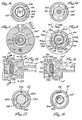
- Figs. 8-14 show a pump according to another embodiment of the present invention.
- the pump includes a check valve which is integral with the armature, i.e. the check valve is operatively coupled to the armature and is located in the fluid-receiving region of the housing for opening and closing the pump inlet.
- the check valve comprises a valve member movably carried by the armature and positioned for closing the pump inlet when the armature is in the rest position and for opening the inlet after the armature begins movement associated with the forward pumping stroke.
- components of the pump of this embodiment which are similar to those of the pump of Figs. 1-7 are identified by the same reference numerasl provided with a prime designation.
- the pump of this embodiment has an armature generally designated 150 including a shaft section 152 of relatively small diameter adjacent one end of the armature, i.e. the left-hand end as viewed in Fig. 8.
- Shaft section 152 is similar to section 112 in the embodiment of Figs. 1-7 but is of relatively shorter axial length.
- An armature pole portion 114' having a pole face 116' and identical to the pole portion and pole face of the armature of Figs. 1-7 is fixed to this end of shaft section 152 by a compression fit between pole portion 114', a Teflon busing 120' and the shaft section in a manner identical to that of the preceeding embodiment.
- Armature 150 includes a shaft section 154 of slightly larger diameter adjacent shaft section 152 in a direction away from end face 118' of pole portion 114'.
- Section 154 meets an armature body portion 158 of larger diameter and formed to-include a plurality, in the present illustration four, radially extending formations or lands 160a-160d as shown also in Fig. 12.
- Each land formation 160a-160d has a relatively short, cuved outer edge 162a-162d, respectively, close to the inner surface 32' for guiding the armature 150 as it moves within the housing.
- Each land is separated from an adjacent land by a corresponding straight edge 163,165 and 166 as shown in Fig.
- the lands 160a-160d also define a plurality of shoulders facing in opposite axial directions for a purpose to be described.
- Armature 150 terminates in an axial end face 167 disposed toward inlet 18'.
- a longitudinal bore 168 extends inwardly from face 167 along within body 158 and terminates in the shaft section 154 for movably carrying the check valve member 170 which now will be described.
- Check valve 170 has a main body 172 and an axial face 174, and the check valve 170 is positioned with face 174 disposed toward the armature end face 167.
- Check valve 170 has a rod or shaft portion 178 extending outwardly in a direction normal to end face 174 and is received in armature passage 168 in slidably movable relation.
- the armature shaft portion 154 is provided with a pair of oppositely directed radially extending bores or passages 182 in communication with the longitudinal passage 163 at the end where check valve shaft portion 178 terminates for a purpose to be described.
- the check valve body 172 has a relatively large diameter portion 184 of relatively short axial length defining an annular shoulder facing toward the lands 160a-160d of the armature.
- the opposite axial end of valve member 170 includes a frustoconical surface 186, a cylindrical surface 188 and a conical top formation 190. These portions of valve 170 extend into an annular valve seat element 192 having a central bore or passage 194, which, in turn, is fixed in the annular recess of body 56' of the fitting defining inlet 18'.
- first biasing means in the form of coil spring 200 between a spring retainer 134' and the annular shoulders defined by lands 160a-160d for urging armature 150 into the rest position.
- second biasing means in the form of coil spring 204 positioned between the annular shoulder defined by lands 160a-160d and the annular shoulder defined by valve section 184 for urging check valve 170 into the position closing intlet 18'.
- the components identified by the primed reference numerals are of the same material and of substantially the same dimensions as corresponding components in the embodiment of Figs. 1-7.
- pole portion 114' is the same material and of substantially the same size as pole portion 114 in Figs. 1-7.
- the remainder of the armature 150 is of titanium, and the overall length measured between the left-hand end of the shaft portion 152 as viewed in Fig. 8 to axial end face 167 is about 0.285 inch.
- Shaft section 152 has a length of about 0.130 inch and a diameter of about 0.036 inch.
- Shaft section 154 has a length of about 0.080 inch and a diameter of about 0.055 inch.
- Body 158 has a length of about 0.075 inch and a diameter of about 0.093 inch.
- Each of the land portions 160a-160d has an axial length of about 0.040 inch, each edge 162a-162d has a length of about 0.020 inch, and edges 162a-162d lie about on a circle having a diameter of about 0.146 inch.
- Valve member 170 is of titanium, and has an overall length of about 0.215 inch between the outer end face of shaft portion 178 to the top of core 190.
- Shaft portion 178 has a length of about 0.100 ) inch and a diameter of about 0.025 inch.
- the two sections of body 172 have outer diameters of 0.093 inch and 0.136 inch.
- Surface 186 has a base angle of about 60° and an axial length of about 0.03 inch.
- the combined axial lengths of surfaces 188 and 190 is about 0.050 inch, surface 188 has a diameter of about 0.030 inch and surface 190 has a base angle of about 60°.
- Valve seat member 192 is of silicone rubber tubing having an outer diameter of about 0.100 inch and an inner diameter of about 0.040 inch.
- Spring 200 provides a force of about 3.5 grams and spring 204 a force of about 1.5 grams.
- inlet 18' is connected to a source or supply of fluid to be pumped, and outlet 20' is connected to a point or location of use for the pumped fluid.
- the armature 150 is moved through the forward pumping stroke in response to electrical energization of electromagnet 70'.
- one way of energizing magnet 70' is to charge a capacitor from a battery and then discharge that capacitor through coil 74.
- Other procedures can of course be employed for electrically energizing coil 74' in a known manner.
- armature 150 Prior to electrical energization of magnet 70', armature 150 is in the rest position illustrated in Fig.
- Electromagnetic flux travels through the magnetic circuit including the electromagnet core 72' plate 78', magnet housing 76', rim 96' of body 90', the included portion of diaphragm 80 between housing 76' and rim 96', body 90', armature pole portion 114', and the gap between pole face 116' and diaphragm 80'.
- armature 150 is moved in the forward pumping stroke, i.e. in a direction to the left as viewed in Figs. 8-10, fluid initially contained in the pumping chamber 16',i.e.
- the check valve member 170 slides freely with respect to the armature 150 and does not necessarily move when the armature 150 is drawn toward diaphragm 80'. Such relative positions are illustrated, for example, in Fig. 10. At rest, the surface 186 of valve member 170 is held in contact with the valve seat defined by passage 194 by the spring 200 acting upon the armature 150 which is then in contact with the check valve member 170 as shown in Fig. 9. When the armature 150 is drawn toward diaphragm 80' the force of spring 200 is-no longer transferred to the check valve member 170 and the force holding the valve member 170 against the valve seat is decreased to that provided by spring 204, which generally provides a force less than that provided by spring 200.
- valve member 170 moves away from the valve seat and fluid flows into the pump body as illustrated in Fig. 8. In fact, because the fluid is nearly incompressible the check valve 170 opens at approximately the same tiem that the armature 150 achieves enough velocity to force fluid out of the pump outlet 20'.
- the forward pumping stroke • of the armature 150 is completed when the pole face 116' approaches contact with the diaphragm 80'. Actual contact may not be achieved since viscosity limits outflow of the fluid between the pole face 116' and the diaphragm 80.
- the armature velocity decreases to a level such that the displacement rate of the motion of the pole portion 114' no longer exceeds the leak rate between the pole portion 114' and the body 90'
- the pressure within the pump housing 12' begins to increase.
- the check valve member moves toward the valve seat and prevents flow out of the inlet port 18' of the pump as illustrated, for example, in Fig. 10.
- armature 150 When electrical excitation of coil 74' ceases, armature 150 is moved in the opposite direction, i.e. to the right as viewed in Figs. 8-10, by the force of biasing spring 200 until the armature reaches the rest position as shown in Fig. 9 with surface 186 seated in the opening of passage 194. This motion is relatively slow since it is limited by the small leak rate of fluid between the outer surface of the pole portion 114' and the surface passage 98' in body 90' at a pressure difference determined by the force applied by the spring 200.
- the check valve member 170 is held against the valve seat primarily by the light spring 204 supplemented by the difference between the outlet and inlet pressures acting on the valve seat.
- Openings 182 allow exit of fluid from the space between passage 168 and valve portion 178.
- the spring force is increased to that of spring 200.
- the average pumping rate which is determined by the rate of return of armature 150 to the rest position can be relatively slow, but such a pumping rate is called for in typical implantable drug delivery systems. Armature 150 then remains in the rest position of Fig. 9 with inlet 18' closed and waiting for the next forward pumping stroke which occurs when magnet 70' is energized again.
- the pump of the embodiment of Figs. 8-14 has all the advantages of the embodiment of Figs. 1-7 including the diaphragm 80' providing an hermetic seal between the fluid in housing 12' and the electrical components associated with magnet 70', the immersed armature 150 making operation of the pump nearly independent of ambient pressure, the electric and magnetic efficiency being provided by minimizing the total gap within the magnetic circuit, by having the magnetic pole face 116' of relatively large surface area, and by having core 72' of relatively small diameter, and the pump being relatively small in size and light in weight.
- the pump of this embodiment has the further advantage of an integral check valve.
- a pump as shown in Figs. 8-14 was pulsed by a 4.7 microfarad capacitor at 15 volts to pass 0.31 microliters against a 2 p.s.i. head.
- the calculated five year energy requirement from the capacitor is 3100 joules. This is approximately 12% of the energy available from a model 7911 lithium-iodine cell commercially avaialbe from Wilson Greatbatch Ltd., Clarence, New York.
- Tables I and II present performance data obtained from operating a pump as shown in Figs. 8-14 with water, a coil resistance of 243 ohms, a 4.7 microfarad capacitor, and with capacitor charging voltages of 15 volts and 20 volts, respectively:
- Tables III and IV present performance data for the pump with water, coil resistance of 243 ohms, 2 p.s.i. pressure difference across the pump, and capacitor magntidues of 3.3 and 4.7 microfarads, respectively:
- the forward pumping stroke has a duration from about 1 to about 5 milliseconds, dependent upon the voltage and the back pressure, and the return stroke has a duration from about 0.1 to about 1.5 seconds.
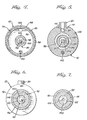
- Figs. 15-18 illustrate a modified form of check valve 210 in the pump of Figs. 8-14.
- the check valve 210 of Figs. 15-18 includes a main body portion 212 similar to body 172 of valve member 170 in Figs. 8-14 and a shaft portion 214 movably received in a longitudinal face of the armature.
- the body 212 is formed to include a plurality of lands 216a-216d similar to lands 160a-160d which define shoulders for engaging the end of spring 204.
- the end face of body 212 facing inlet 18' is provided with a recess to accomodate a disc-shaped valve element 220 and a spring-member 224.
- Disc 220 is of silicon rubber and spring member 224 is a thin disc of titanium foil contoured as shown in Figs. 15 and 16 to enable disc 220 to rock within the recess.
- disc 220 is captive within the recess but not attached to it.
- the passage 64' of the fitting providing inlet 18' terminates in an outwardly flared surface portion 228 defining a valve seat edge 130 of diameter layer than passage 64'.
- Disc 220 is of slightly larger diameter and is adpated to seat on edge 226.
- Figs. 15 and 16 illustrate the unseated and seated conditions of the check valve. The ability of disc 220 to rock within the recess by virtue of spring 224 ensures that disc 220 lies flat on valve seat 230.
- the check valve of Figs. 15-18 has a number of advantages.
- the flow area in the open portion at the same stroke is relatively larger, and therefore the pressure drop across the check valve is relatively lower.
- Seating of valve element 220 on seat 230 does not involve a rubbing motion, and therefore the possibility of unacceptable wear on the seat is reduced.
- the arrangement of Figs. 15-18 is relatively easy to manufacture.
- valve element 220 has a diameter of about 0.100 inch and a thickness of about 0.030 inch
- spring 224 has a diameter of about 0.100 inch and a thickness of about 0.002 inch
- surface 228 defines an angle of about 45° with the housing longitudinal axis.
- a pump 310 includes a housing 312 which is generally hollow cylindrical in overall shape and includes an interior region for containing fluid, i.e. the liquid to be pumped. As shown in Fig. 20, the hollow interior region is dividied in a manner which will be described into a fluid receiving chamber 314, a first fluid pumping chamber 316 in fluid communication with receiving chamber 314, and a second fluid pumping chamber 318 serially in fluid communication with pumping chamber 316. There is an inlet generally designated 320 in fluid communication with the receiving chamber 314 and adapted to be connected to a source or supply of fluid to be pumped.
- outlet 322 in fluid communication with the second pumping chamber 318 and adapted to be in fluid communication with a location to which the fluid is to be pumped.
- check valve means operatively associated with the fluid containing region of pump 310 for allowing fluid flow in a direction from the inlet 320 through outlet 322 and blocking fluid flow in a direction from the outlet through the inelt.
- the check valve is within the pump and associated with the pump armature in a manner which will be described.
- housing 312' is generally hollow cylindrical in overall shape including a main body portion 326 of relatively substantial wall thickness.
- Housing portion 326 has a first axial end section 328 extending from one end of housing portion 326, i.e. the right-hand end as viewed in Fig. 20, which is of relatively smaller wall thickness and terminates in an axial end face 330.
- Portion 326 and section 328 define an interior surface of constant diameter.
- the housing portion 326 has a second axial end section 338 extending from the other end of housing section 326, i.e. the left-hand end as viewed in Fig. 20, which also is of smaller wall thickness.
- End section 338 has a relatively larger diameter inner wall surface 340 which meets surface 332 in annular intermediate wall 342.
- Main body portion 326 is provided with a longitudinal bore or passage 344 for placing the second pumping chamber 318 in fluid communication with outlet 322.
- Outlet 322 is located on the side of housing 312 for communication with the passage 344.
- Housing portion 328 is provided with a radially extending opening in the outer wall thereof in communication with passage 344.
- a housing extension portion 346 is provided between main body portion 328 and inlet 320.
- Portion 346 is generally cylindrical having first and second axial sections 348 and 350, respectively.
- Section 348 is received snugly within housing section 328 with section 348 having an outer diameter substantially the same as the diameter of surface 332.
- Section 348 has an inner surface 352 and terminates in an axial end face 354 exposed to the first pumping chamber 316.
- Section 350 has an outer diameter substantially equal to the outer diameter of housing section 328 whereby the outer surfaces thereof are substantially flush.
- the outer surface of section 350 meets the smaller diameter outer surface of section 348 in an annular surface 356 which abuts end face 330.
- Section 350 has an inner surface 358 of a diameter larger than that of inner surface 352 of section 348, and the two inner surfaces 352,358 meet in an annular surface 360.
- Section 350 terminates in an axial end face 362.
- Inlet 320 is provided by a plug-like element which is fitted into the open end of section 350 of the housing extension portion 346.
- the element includes a main body 336 generally cylindrical in shape and having an outer diameter substantially equal to the diameter of inner surface 358 of section 350 thereby providing a close fit therein.
- Body 366 has one axial end face 368 located in chamber 314, and adjacent the opposite end face the outer surface of body 366 is provided with an annular rim 370 which abuts the annular end face 362 for placement and securement of the fitting in the housing. The two components are secured together by welding or other suitable means.
- An internal bore 372 extends between the two opposite axial end faces of body 366 to provide an internal passage for the inlet. Passage 372 meets the inner axial end face 368 an annular, conical shaped surface 374.
- Inlet 320 is adapted for connection to a conduit such as a flexible tubing leading from a source or supply of fluid to be pumped.
- housing 312 including main body portion 326 and extension portion 346, together with the inlet and outlet fittings 318 and 320, respectively, all are of metal, and for a drug delivery pump for implantation in a patient, titanium has been found to provide satisfactory results.
- housing 312 has an overall length of about 0.555 inch measured between the axial end faces of section 338 and 350.
- Surface 332 has a diameter of about 0.15 inch, and the axial end face 330 has a radial dimension of about 0.03 inch.
- Surface 340 has a diameter of about 0.26 inch, and the axial end face of housing section 338 has a radial thickness of about 0.02 inch.
- Surface 352 has a diameter of about 0.100 inch
- axial end face 354 has a radial dimension of about 0.050 inch.
- Surface 358 has a diameter of about 0.135 inch
- axial end face 362 has a radial dimension of about 0.040 inch. The axial distance between end faces 354 and 362 is about 0.260 inch.
- the passage 372 has a diameter of about 0.034 inch and surface 374 is disposed at an angle of about 45 degrees to the longitudinal axis of fittings 320.
- the pump of the present invention further comprises electromagnet means generally designated 380 carried by housing 312 and located external to the fluid containing region of the housing.
- the electromagnet 380 includes a core 382 in the form of a spool which is generally solid cylindrical in shape.
- a coil 384 is wound on spool 382 and contained within a hollow housing 386 generally cylindrical in shape.
- One end of electromagnet 380 is adjacent and in abutting relation to housing 321, and the opposite end,i.e. the left-hand end as viewed in Fig. 20, is closed by a plate element 388 fitted within the open end of housing 386 and fitted onto an end of spool 382.
- Electromagnet is joined to housing 321 in the following manner.
- the interior, fluid containing region of housing 321 and the electromagnet 380 are separated by a barrier means of fluid impervious material in the form of a relatively thin plate or diaphragm-like component 390.
- the end of magnet housing 386 adjacent housing 312 is provided with an annular band 392 around the outer surface and adjacent the axial end face of housing 386.
- the outer diameter of band 392 when placed on housing 386 is substantially equal to the outer diameter of housing section 338 so that the respective outer surfaces are substantially flush.
- the axial end faces of band 392 and magnet housing 386 are coplanar.
- the housing and electromagnet structures are placed in abutting relation on opposite surface portions of the plate 390, and the assembly secured together by a weld joining the respective adjacent outer surfaces of band 392 and housing section 338.
- an enlarged annular end portion 394 of spool 382 contacts the central portion of plate 390 in a manner supporting the same.
- spool 382 magnet housing 386 and closure 388 are of ferromagnetic material, for example 4750 nickel iron alloy.
- Plate 390 and band 392 are of titanium, the material of plate 390 being found suitable for use in the exemplary implanted drug delivery pump previously mentioned.
- Spool 382 has a length of about 0.555 inch and a diameter of 0.079 inch.
- Housing 386 has a wall thickness of about 0.03 inch, band 392 a thickness of about 0.02 inch and diaphragm 390 a thickness of about 0.001 inch.
- Coil 384 has about 3600 turns of 42 gauge wire.
- the pump of the present invention further comprisies a body 400 of magnetically permeable material in the fluid containing region of housing 312 and between the first and second fluid pumping chambers 316 and 318,respectively.
- body 400 also defines a portion of the magnetic circuit in the pump, along with other components of the pump, in a manner which will be described.
- Body 400 is generally solid cylindrical in shape having an outer diameter substantially equal to the diameter of housing inner surface 340 of housing section 338 thereby providing a close fitting relationship.
- Body 400 has a main body portion between axial end surfaces 402 and 404 which is of an axial length less than the distance between housing surface 342 and plate 390 by an amount determined by the desired dimension of pumping chamber 318.
- Body 400 is formed to include an outer annular rim portion 406 extending from end face 402 and which abuts a corresponding surface portion of plate 390 as shown in Fig. 20.
- the radial thickness of rim portion 406 is substantially equal to that of magnet housing 386, and the two are in substantial alignment for maximizing transmission of magnetic flux therebetween in a manner which will be described.
- Body 400 is provided with a central through bore or passage 408 of substantial diameter for receiving a portion of the pump armature in a manner which will be described.
- the main portion of body 400 also is provided with a smaller through bore or passage 410 offset from passage 408 and of substantially the same diameter and inregistry with outlet passage 344 thereby providing fluid communication between pumping chamber 318 and the outlet 322.
- Body 400 is positioned in housing 312 by means of a rod 412 extending through corresponding bores in body 400 and valve housing portion 326 shown in Fig. 20, the rod 412 preferably being of Teflon material and the parts being secured together by a compression fit.
- body 400 is of mu metal which is selected to provide the desired degree of magnetic permeability while at the same time being compatible with medicine or the like for use in the exemplary implanted drug delivery pump previously mentioned.
- mu metal includes nickel in a major portion with the balance including iron, copper and chromium.
- some or all of the external surfaces of body 400 can be plated or coated by palladium or other suitable material selected to enhance the compatibility of the drug with the external surface.
- the outer diameter of body 400 is about 0.26 inch, the axial length between end face 404 and the end face of rim 406 is about 0.130 inch, and the axial length between end faces 402,202 is about 0.1 inch.
- Passage 410 has a diameter of about 0.029 inch and the central passage 408 a diameter of about 0.1 inch.
- the pump according to the present invention further comprises an armature generally designated 420 positioned in the fluid containing region of housing 312.
- the armature has a pole portion located for magnetic attraction by the electromagnet 380, a first plunger portion associated with the first pumping chamber 316 for forcing fluid from chamber 316 into chamber 318, and a second plunger portion associated with the second pumping chamber 318 for forcing fluid out of chamber 318 and outlet 322.
- the armature 420 is movably supported in housing 312 for movement from a rest position through a forward pumping stroke when attracted by the electromagnet 390 to force fluid out of the pumping chambers 316 and 318 through outlet 322, and for movement in an opposite direction through a return stroke backe to the rest position.
- armature 420 is shown in a position at the end of the forward pumping stroke in response to energization of electromagnet 380, in Fig. 21 armature 420 is shown in the rest position at the end of the return stroke, and in Fig. 22 armature 420 is shown in an energized position and the check valve in a closed position which will be described in detail presently.
- Armature 420 includes a shaft or rod portion 422 which is positioned in housing 312 with the longitudinal axis thereof generally coincident with the longitudinal axis of housing 312. Shaft portion 422 is of relatively small diameter.
- the armature further includes an enlarged body portion 424 of magnetically permeable material which provides the armature pole portion and the second plunger portion in a manner which will be described.
- Body 424 is solid cylindrical in shape having an outer diameter slightly smaller than the diameter of passage 408 in body 400. This is to allow reciprocal movement of armature body 424 within the body 400 during the forward and return strokes of armature 420.
- the sizes of the outei diameter of body 424 and the diameter of passage 408 are selected to provide a fluid leakage path from pumping chamber 318 to pumping chamber 318 to pumping chamber 316 during the armature return stroke in a manner which will be described.
- the armature body 124 terminates at the end facing electromagnet 380 in an axial end face 426 which serves as the pole face and is disposed substantially perpendicular to the armature axis.
- the pole face 426 together with electromagnet 380 define the magnetic circuit gap which is closed during the forward pumping stroke.
- the pole face 426 is of relatively large cross-sectional area as compared to the cross sectional area of the armature shaft portion 422.
- the body 424 also serves as one of the armature plunger portions because as the pole face 426 moves toward plate 390 during the forward stroke when magnet 386 is energized, body 424 upon moving inot pumping chamber 318, displaces fluid therefrom forcing it out through passages 400,344 to outlet 322.
- Shaft portion 422 is fixed to body 424 in the following manner.
- Body 424 is provided with a longitudinal bore extending inwardly from the opposite axial end face 428 which terminates within body 424 at a location spaced from pole face 426.
- a sleeve 430 or a suitable split bushing of fluoropolymer material such as Teflon is fitted in the bore, and the end of the armature shaft portion 422 is fixed in the sleeve or bushing 430.
- the foregoing is provided by a mechanical compression fit.
- the outer surface of body 424 is provided with a coating 432 of Teflon or like material for a purpose to be described.
- Armature 420 includes another body portion 433 spaced axially from body 424, preferably integral with shaft portion 422, and of relatively larger diameter.
- Body portion 434 provides the armature first plunger portion in a manner which will be described.
- Body portion 434 has an outer surface extending along a major portion of the axial length of body 434 and having an outer diameter slightly less than the diameter of inner surface 352 of housing section 348. This is to allow reciprocal movement of body portion 434 within housing section 348 during the forward and return strokes of armature 420.
- the sizes of the outer diameter of surface 436 and the inner diameter of surface 352 are selected to provide a fluid leakage path from pumping chamber 316 to receiving chamber 314 during the armature return stoke in a manner which will be described.
- Body 434 terminates at the end facing body 424 in an annular end face 438 disposes substantially perpendicular to the armature axis and extending between the outer surface of body 424 and the shaft portion 422.
- Body 434 is formed to include an annular extension or flange 440 between surface 436 and end face 438, located a short axial distance from end face 438.
- Flange 440 includes opposite side faces 442,444 and an outer peripheral face 446 spaced from housing inner surface 332.
- An annular outer surface 448 of body 434 and having a diameter slightly less than that of surface 436 is between flange 440 and end face 438.
- Surface 448 together with flange face 442 define an annular shoulder facing in an axial direction toward body 424 for a purpose to be described.
- first biasing means in the form of a coil spring 450 for urging armature 420 toward the rest position shown in Fig. 21.
- spring 450 seats in the annular shoulder described above and defined by the flange 440 and body surface 448.
- the opposite end of spring 450 seats in an annular spring retainer element 452 which has an annular rim portion which abuts against the end face 404 of body 400 as shown in Fig. 20.
- the annular shape of retainer 452 with the two diameter rim sections, enables it to be located concentric with the armature shaft section 422 to receive the spring 450 which also is concentric with the shaft, while at the same time not interfering with body 424 during movement of the armature 420.
- the outer diameter of the largest rim portion of retainer 452 is substantially equal to the diameter of surface 332, and retainer 452 is merely located with the housing 312, being held in place by the force of spring 450.
- Body 434 terminates at the end facing inlet 320 in an annular end face 458 disposes substantially perpendicular to the armature axis and meeting an axial extension 460 of relatively short axial length disposed toward inlet 320 and having a diameter approximately equal to the diameter of armature shaft portion 422. Extension 460 operatively engages the pump check valve in a manner which will be described.
- End face 458 terminates at the outer periphery thereof in an annular surface 462 of body 434 which has a diameter less than the diameter of surface 436 and which extends a relatively small distance axially inwardly from end face 458.
- Surface 462 terminates in an annular surface 464 disposed substantially perpendicular to the armature axis and which meets surface 436. Surfaces 462 and 464 define an annular shoulder facing inlet 320 for a purpose to be described.
- the armature 420 including shaft portion 422 and body portion 434 is machined from metal, preferably titanium for use in the aforementioned illustrative implanted drug delivery pump.
- Armature body 424 is of mu metal and retainer 452 is of titanium.
- the armature can be coated or plated with gold, or other suitable material, like body 400, chose to enhance the compatibility of the drug with the external surface.
- the Teflon coating 432 on the outer surface of body 424 received in passage 408 serves to reduce friction.
- the combined of armature shaft portion 422 and body portion has an overall length of about 0.410 inch from the end fitted within body 424 to the outer end of the extension 460.
- the armature shaft portion 422 has a diameter of about 0.036 inch, surface 436 has a diameter of about 0.100 inch, surface 436 of flange 440 has a diameter of about 0.136 inch, surface 448 has a diameter of about 0.094 inch, extension 460 has a diameter of about 0.030 inch and surface 462 has a diameter of about 0.080 inch. From the outer end of extension 460, surfaces 458,464 and 444 are spaced axially therefrom distances of about 0.040 inch, 0.060 inch and 0.180 inch, respectively.
- Flange surface 464 has an axial width of about 0.015 inch and the distance between end face 438 and flange surface 444 is about 0.035 inch.
- Body 424 has an overall axial length of about 0.14 inch and an outer diameter of about 0.1 inch.
- Spring 450 is 0.005 titanium wire with the spring inner diameter being about 0.095 inch.
- the pump according to the present invention further includes a check valve which is integral with the armature, i.e. the check valve is operatively coupled to the armature and is located in the fluid-receiving region of the housing for opening and closing the pump inlet.
- the check valve comprises a valve member movably carried by the armature and positioned for closing the pump inlet when the armature is in the rest position and for opening the inlet after the armature begins movement associated with the forward pumping stroke. As shown in Figs.
- the check valve is located in fluid receiving chamber 314 between inlet 320 and the end of armature 420 and includes a main body portion 470 generally cylindrical in shape having an outer surface 472 spaced radially inwardly from housing surfaces 352,358.
- Surface 472 has a diameter substantially the same as that of surface 462 of body 434.
- Body portion 470 terminates at the end facing armature 420 in an axial end face 474 disposed substantially perpendicular to the longitudinal axis of armature 420.
- An axially inwardly extending recess in the form of bore 476 is provided in surface 474 coaxial with the longitudinal axis of armature 420 and extending along within check valve body 470.
- Recess 476 receives extension 460 of armature body 434.
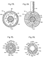
- the check valve body 470 is formed to include a plurality, in the present illustration four, radially extending formations or lands 480a-480d as shown also in Figs. 25 and 26.
- Each land formation 480a-480d has a relatively short, curved outer edge 482a-482d, respectively, close to the inner surface 358 of housing section 350 for guiding the check valve 468 as chamber 314.
- Each land is separated from an adjacent land by a corresponding straight edge 483, 484, 485, and 486 as shown in Figs. 25 and 26 thereby providing a flow space of significant area between the particular straight edge and the corresponding curved portion of surface 358.
- the lands 480a-480d also define a plurality of shoulders facing in an axial direction toward armature 420 for a purpose to be described.
- the end face of body 470 facing inlet 320 is provided with a recess 490 to receive a disc-shaped valve element 492 having a smooth, convex outer surface 494 facing inlet 320.
- surfaces 374 and 368 of inlet fitting 320 meet in a sharp, annular valve seat edge 196 which is contacted in seating contact or engagement by surface 494 of valve element 492.
- Edge 496 is of a diameter larger than the diameter of inlet passage 372.
- second biasing means for urging check valve 468 into a position closing inlet 320.
- valve element surface 494 is biased into seating contact with edge 496 by the second biasing means acting on check valve 468 in the form of coil spring 498.
- One end of spring 498 i.e.
- check valve body 470 is of titanium and has an overall axial length of about 0.070 inch.
- Surface 472 of valve body 470 has a diameter of about 0.080 inch and bore 476 has a diameter of about 0.030 inch and an axial length of about 0.030 inch.
- Each of the land portions 480a-480d has an axial length of about 0.040 inch, each edge 482a-482d has a length of about 0.020 inch and edges 482a-482d lie about on a circle having a diameter of about 0.130 inch.
- Recess 490 has a diameter of about 0.100 inch and an axial length of about 0.025 inch.
- Valve element 492 is of Dow Corning Silastic material MDX4-4210 which is heat cured in place into recess 492.
- Surface 374 of inlet fitting 320 defines an angle of about 45 degrees with the housing longitudinal axis.
- Spring 498 is 0.005 diameter titanium wire with the spring inner diameter being about 0.182 inch.
- inlet 320 is connected to a source or supply of fluid to be pumped, and outlet 322 is connected to a point or location of use for the pumped fluid.
- the armature 420 is moved through a forward pumping stroke in response to electrical energization of electromagnet 380.
- One way of energizing magnet 380 is to charge a capacitor from a battery and then discharge that capacitor through coil 384.
- Other procedures can of course be employed for electricall energizing coil 384 in a known manner.
- armature 420 Prior to electrical energization of magent 380, armature 420 is in the rest position illustrated in Fig.
- Electromagnetic flux travels through the magnetic circuit including the electromagnet core 382, magnet housing 386, rim 406 of body 400, the included portion of diaphragm 390 between housing 386 and rim 400, body 400, armature pole portion 424, and the gap between pole face 426 and diaphragm 390.
- armature 420 is moved in the forward pumping stroke, i.e. in a direction to the left as viewed in Figs. 20-22, fluid initially contained in the first pumping chamber 316, i.e.
- the check valve 468 slides freely with respect to the armature 420 and does not necessarily move when the armature 420 is drawn toward diaphragm 390. Such relative positions are illustrated, for example, in Fig. 22.
- the surface 494 of check valve element 492 is held in contact with the valve seat defined by edge 496 by the spring 450 acting upon the armature 420 which is then in contact with the check valve body 470 as shown in Fig. 20.
- the force of spring 450 is no longer transferred to the check valve 468 and the force holding the valve surface 495 against - the valve seat is decreased to that provided by spring 498,which generally provides a-force less than that provided by spring 450.
- the forward pumping stroke of the armature 420 is completed when the pole face 426 approaches . contact with the diaphragm 390. Actual contact may not be achieved since viscosity limits outflow of the fluid between the pole face 426 and the diaphragm 390.
- the armature velocity decreases to a level such that the displacement rate of the motion of thepole portion 424, no longer exceeds the leak rate between the outer surface 436 of armature body portion 434 and inner surface of housing section 348, the pressure within the pump housing 312 begins to increase.
- the check valve member moves toward the valve seat and prevents flow out of the inlet port 320 of the pump as illustrated, for example, in Fig. 22.
- armature 420 When electrical excitation of coil 384 ceases, armature 420 is moved in the opposite direction, i.e. to the right as viewed in Figs. 20-22, by the force of biasing spring 450 until the armature reaches the rest position as shown in Fig. 21 with surface 494 seated on edge 496 surrounding the opening of passage 372.
- This motion is relatively slow since it is limited by the small leak rate of fluid between the outer surface 436 of armature body portion 434 and th inner surface 352 of housing section 348 at a pressure difference determined by the force applied by the spring 450.
- armature portion 434 and the housing sections 348,350 at the inlet end of pump 310 results in a major decrease in the internal volume between the pump piston or armature 420 and the pump check valve 468.
- This reduction has the effect of making the pump less sensitive to the possible presence of a bubble in the fluid within the pump.
- the pump 319 is much easier to prime, and the use of carbon dioxide is normally not required for this purpose.
- the flow rate decreases temporarily but recovers to its normal level as the bubble dissolves in the fluid.
- the volume per stroke of pump 310 is relatively less sensitive to back pressure.
- the gap or clearance between armature pole portion 424 and passage 408 is relatively less critical to the extent that pump 310 relies on armature plunger portion 434 in addition to plunger portion 424 to provide the pressure increase.
- the Teflon coating 432 on the pole button or body 425 avoids high side forces on the pole button and the resulting drag as the pole button is pulled in a direction toward the armature spindle or shaft portion 422.
- the use of the Teflon coating 432 which is soft and somewhat uneven, makes it difficult to maintain a small clearance between the pole button 434 and the solenoid ring or body 400. In pump 310 greater clearance is allowable between these two parts. The requirement for close tolerance is shifted to two titanium parts which may not need to be coated, i.e. the armature portion 434 and the housing section 348.
- armature plunger portions 434 and 424 in pumping chambers 316 and 318, respectively provides two pumping elements in series. A higher pressure increse across pump 310 would appear to be possible and a bubble in one of the pumping chambers would affect one but not both pumping elements.
- pump 310 of the present invention has the advantage of being relatively insensitive to the presence of bubbles in the fluid being handled, being relatively easy to prime, and providing an adequate fluid pressure increase across the pump sufficient for the uses intended.
- Pump 310 also has the advantage of operating at extremely low power levels, being compatible with drugs and similar liquids to be pumped, being electrically and magnetically efficient, and being small in size, light in weight and reliable in operation.
- the non-movable diaphragm 390 of titanium or like material provides an hermetic seal between the fluid in housing 312 and the the electrical components associated with magnet 380. Having armature 420 immersed in the fluid makes operation of the pump nearly independent of ambient pressure.
- the initial condition of the pump when armature 420 is in the rest position of Fig. 21 is that the fluid is at substantially the same pressure on opposite sides of the pump piston, i.e. in the receiving chamber 314 and in the pumping chambers 316 and 318.
- the pump of the present invention is made electrically and magnetically efficient by minimizing the total gap within the magnetic circuit, by having the magnetic pole face 426 of relatively large.surface area, and by having core 382 of relatively small diameter.
Landscapes
- Engineering & Computer Science (AREA)
- Health & Medical Sciences (AREA)
- General Engineering & Computer Science (AREA)
- Mechanical Engineering (AREA)
- Biomedical Technology (AREA)
- Public Health (AREA)
- Vascular Medicine (AREA)
- Anesthesiology (AREA)
- Veterinary Medicine (AREA)
- Heart & Thoracic Surgery (AREA)
- Hematology (AREA)
- Life Sciences & Earth Sciences (AREA)
- Animal Behavior & Ethology (AREA)
- General Health & Medical Sciences (AREA)
- Fluid Mechanics (AREA)
- Physics & Mathematics (AREA)
- Reciprocating Pumps (AREA)
- Electromagnetic Pumps, Or The Like (AREA)
- Details Of Reciprocating Pumps (AREA)
Priority Applications (1)
| Application Number | Priority Date | Filing Date | Title |
|---|---|---|---|
| AT83305009T ATE31201T1 (de) | 1982-09-07 | 1983-08-31 | Elektromagnetische pumpe mit niedriger leistung. |
Applications Claiming Priority (4)
| Application Number | Priority Date | Filing Date | Title |
|---|---|---|---|
| US415657 | 1982-09-07 | ||
| US06/415,657 US4569641A (en) | 1982-09-07 | 1982-09-07 | Low power electromagnetic pump |
| US06/496,822 US4568250A (en) | 1982-09-07 | 1983-05-23 | Low power electromagnetic pump |
| US496822 | 1983-05-23 |
Publications (3)
| Publication Number | Publication Date |
|---|---|
| EP0102824A2 true EP0102824A2 (fr) | 1984-03-14 |
| EP0102824A3 EP0102824A3 (en) | 1985-01-23 |
| EP0102824B1 EP0102824B1 (fr) | 1987-12-02 |
Family
ID=27023054
Family Applications (1)
| Application Number | Title | Priority Date | Filing Date |
|---|---|---|---|
| EP83305009A Expired EP0102824B1 (fr) | 1982-09-07 | 1983-08-31 | Pompe électromagnétique à basse puissance |
Country Status (4)
| Country | Link |
|---|---|
| US (1) | US4568250A (fr) |
| EP (1) | EP0102824B1 (fr) |
| DE (1) | DE3374795D1 (fr) |
| IL (1) | IL69613A (fr) |
Cited By (3)
| Publication number | Priority date | Publication date | Assignee | Title |
|---|---|---|---|---|
| EP0170367A3 (en) * | 1984-06-05 | 1987-01-21 | Greatbatch Enterprises, Inc. | Low power electromagnetic pump |
| EP0259668A1 (fr) * | 1986-09-01 | 1988-03-16 | Siemens Aktiengesellschaft | Pompe à piston pour appareil de dosage de substances médicamenteuses |
| FR2726331A1 (fr) * | 1994-10-31 | 1996-05-03 | Ono Harry | Pompe a piston double |
Families Citing this family (30)
| Publication number | Priority date | Publication date | Assignee | Title |
|---|---|---|---|---|
| WO1987003342A1 (fr) * | 1985-11-21 | 1987-06-04 | Industria De Motores Anauger Ltda. | Pompe vibratoire |
| EP0287920B1 (fr) * | 1987-04-22 | 1991-05-15 | Siemens Aktiengesellschaft | Pompe à piston pour le dosage de médicaments |
| US5290159A (en) * | 1993-03-04 | 1994-03-01 | Exxon Production Research Company | Downhole pump of constant differential hydraulic pressure |
| US5433710A (en) * | 1993-03-16 | 1995-07-18 | Minimed, Inc. | Medication infusion pump with fluoropolymer valve seat |
| DE69535019T2 (de) * | 1994-03-11 | 2007-01-04 | Wilson Greatbatch, Ltd. | Elektromagnetische pumpe mit geringem vermögen |
| WO1996000095A1 (fr) * | 1994-06-23 | 1996-01-04 | Minimed Inc. | Pompe de perfusion de medicaments a siege de soupape en fluoropolymere |
| US6443942B2 (en) | 1996-11-01 | 2002-09-03 | Minimed, Inc. | Medication device with protein stabilizing surface coating |
| US7201746B2 (en) * | 2001-04-10 | 2007-04-10 | Medtronic, Inc. | Implantable therapeutic substance delivery device having a piston pump with an anti-cavitation valve |
| US7288085B2 (en) * | 2001-04-10 | 2007-10-30 | Medtronic, Inc. | Permanent magnet solenoid pump for an implantable therapeutic substance delivery device |
| US7066915B2 (en) * | 2001-04-10 | 2006-06-27 | Medtronic, Inc. | Low profile inlet valve for a piston pump therapeutic substance delivery device |
| ATE369885T1 (de) * | 2001-04-10 | 2007-09-15 | Medtronic Inc | Flachprofiliges einlassventil für ein auf einer kolbenpumpe basiertes gerät zum zuführen eines medizinischen stoffes |
| US6997921B2 (en) * | 2001-09-07 | 2006-02-14 | Medtronic Minimed, Inc. | Infusion device and driving mechanism for same |
| US6770067B2 (en) * | 2001-09-07 | 2004-08-03 | Medtronic Minimed, Inc. | Infusion device and driving mechanism for same |
| US7186236B2 (en) * | 2001-09-07 | 2007-03-06 | Medtronic Minimed, Inc. | Infusion device and inlet structure for same |
| US20090118711A1 (en) * | 2001-09-07 | 2009-05-07 | Medtronic, Inc. | Reduced-noise implantable infusion device |
| US9492111B2 (en) * | 2002-04-22 | 2016-11-15 | Medtronic Minimed, Inc. | Methods and materials for stabilizing analyte sensors |
| US7813780B2 (en) * | 2005-12-13 | 2010-10-12 | Medtronic Minimed, Inc. | Biosensors and methods for making and using them |
| US20070227907A1 (en) * | 2006-04-04 | 2007-10-04 | Rajiv Shah | Methods and materials for controlling the electrochemistry of analyte sensors |
| US20040074785A1 (en) * | 2002-10-18 | 2004-04-22 | Holker James D. | Analyte sensors and methods for making them |
| US9237865B2 (en) * | 2002-10-18 | 2016-01-19 | Medtronic Minimed, Inc. | Analyte sensors and methods for making and using them |
| US20050272989A1 (en) * | 2004-06-04 | 2005-12-08 | Medtronic Minimed, Inc. | Analyte sensors and methods for making and using them |
| US6932584B2 (en) * | 2002-12-26 | 2005-08-23 | Medtronic Minimed, Inc. | Infusion device and driving mechanism and process for same with actuator for multiple infusion uses |
| US7255690B2 (en) * | 2002-12-26 | 2007-08-14 | Medtronic Minimed, Inc. | Infusion device having piston operated driving mechanism and positive pressure reservoir |
| US8007247B2 (en) * | 2007-05-22 | 2011-08-30 | Medtronic, Inc. | End of stroke detection for electromagnetic pump |
| US9968733B2 (en) * | 2008-12-15 | 2018-05-15 | Medtronic, Inc. | Air tolerant implantable piston pump |
| US8660628B2 (en) * | 2009-12-21 | 2014-02-25 | Medtronic Minimed, Inc. | Analyte sensors comprising blended membrane compositions and methods for making and using them |
| BRPI1103647A2 (pt) * | 2011-07-07 | 2013-07-02 | Whirlpool Sa | disposiÇço entre componentes de compressor linear |
| BRPI1103447A2 (pt) * | 2011-07-19 | 2013-07-09 | Whirlpool Sa | feixe de molas para compressor e compressor provido de feixe de molas |
| BRPI1104172A2 (pt) * | 2011-08-31 | 2015-10-13 | Whirlpool Sa | compressor linear baseado em mecanismo oscilatório ressonante |
| EP3891394B1 (fr) * | 2018-12-03 | 2023-07-19 | Ceme S.p.A. | Pompe pour doser un fluide |
Family Cites Families (13)
| Publication number | Priority date | Publication date | Assignee | Title |
|---|---|---|---|---|
| US1590868A (en) * | 1924-05-09 | 1926-06-29 | Gen Motors Res Corp | Fuel pump |
| US1690348A (en) * | 1925-05-25 | 1928-11-06 | Gen Motors Res Corp | Electromagnetic motor |
| GB685143A (en) * | 1949-06-20 | 1952-12-31 | Enrique Clapes Massons | Electromagnetically operated pump for raising liquids |
| GB687756A (en) * | 1950-10-17 | 1953-02-18 | Enrique Clapes Massons | Electromagnetically operated pump for raising liquids |
| US2634805A (en) * | 1951-04-04 | 1953-04-14 | Gilbert & Barker Mfg Co | Dual rate liquid atomizing apparatus and dual firing rate oil burner embodying the same |
| US3572980A (en) * | 1969-02-17 | 1971-03-30 | Rotron Inc | Resonant pump using flat disc springs |
| US3601509A (en) * | 1969-08-11 | 1971-08-24 | Valcor Eng Corp | Electromagnetic pump |
| DE2315842B2 (de) * | 1973-03-30 | 1977-12-29 | Fa. J. Eberspächer, 7300 Esslingen | Durch einen elektromagneten betaetigte brennstoffkolbenpumpe, insbesondere fuer brennstoffeuerungen |
| GB1496147A (en) * | 1974-12-09 | 1977-12-30 | Eberspaecher J | Piston-type metering pumps |
| US4152098A (en) * | 1977-01-03 | 1979-05-01 | Clark Ivan P | Micropump |
| JPS5584880A (en) * | 1978-12-18 | 1980-06-26 | Toyoda Autom Loom Works Ltd | Compressor |
| JPS56501289A (fr) * | 1979-09-27 | 1981-09-10 | ||
| US4274407A (en) * | 1979-11-13 | 1981-06-23 | Med Pump, Inc. | Fluid injection system |
-
1983
- 1983-05-23 US US06/496,822 patent/US4568250A/en not_active Expired - Lifetime
- 1983-08-31 EP EP83305009A patent/EP0102824B1/fr not_active Expired
- 1983-08-31 DE DE8383305009T patent/DE3374795D1/de not_active Expired
- 1983-08-31 IL IL69613A patent/IL69613A/xx not_active IP Right Cessation
Cited By (4)
| Publication number | Priority date | Publication date | Assignee | Title |
|---|---|---|---|---|
| EP0170367A3 (en) * | 1984-06-05 | 1987-01-21 | Greatbatch Enterprises, Inc. | Low power electromagnetic pump |
| EP0259668A1 (fr) * | 1986-09-01 | 1988-03-16 | Siemens Aktiengesellschaft | Pompe à piston pour appareil de dosage de substances médicamenteuses |
| US4808089A (en) * | 1986-09-01 | 1989-02-28 | Siemens Aktiengesellschaft | Reciprocating pump for a medication administering device |
| FR2726331A1 (fr) * | 1994-10-31 | 1996-05-03 | Ono Harry | Pompe a piston double |
Also Published As
| Publication number | Publication date |
|---|---|
| EP0102824A3 (en) | 1985-01-23 |
| EP0102824B1 (fr) | 1987-12-02 |
| DE3374795D1 (en) | 1988-01-14 |
| IL69613A (en) | 1991-04-15 |
| US4568250A (en) | 1986-02-04 |
| IL69613A0 (en) | 1983-11-30 |
Similar Documents
| Publication | Publication Date | Title |
|---|---|---|
| EP0102824B1 (fr) | Pompe électromagnétique à basse puissance | |
| US4569641A (en) | Low power electromagnetic pump | |
| US4714234A (en) | Low power electromagnetic valve | |
| US4636150A (en) | Low power electromagnetic pump | |
| US6193477B1 (en) | Low power electromagnetic pump | |
| US6932584B2 (en) | Infusion device and driving mechanism and process for same with actuator for multiple infusion uses | |
| US6997921B2 (en) | Infusion device and driving mechanism for same | |
| US4684368A (en) | Inverted pump | |
| US7255690B2 (en) | Infusion device having piston operated driving mechanism and positive pressure reservoir | |
| US20100232992A1 (en) | Actuator with grooved piston for a fluid infusion device | |
| WO2007137194A2 (fr) | Pompe électromagnétique de faible consommation et dispositif de perfusion implantable comportant une telle pompe | |
| EP0746714B1 (fr) | Electrovanne a basse consommation de courant | |
| EP0104787B1 (fr) | Clapet électromagnétique à basse force motrice | |
| US20030086799A1 (en) | Low power electromagnetic pump |
Legal Events
| Date | Code | Title | Description |
|---|---|---|---|
| PUAI | Public reference made under article 153(3) epc to a published international application that has entered the european phase |
Free format text: ORIGINAL CODE: 0009012 |
|
| AK | Designated contracting states |
Designated state(s): AT BE CH DE FR GB IT LI LU NL SE |
|
| PUAL | Search report despatched |
Free format text: ORIGINAL CODE: 0009013 |
|
| AK | Designated contracting states |
Designated state(s): AT BE CH DE FR GB IT LI LU NL SE |
|
| 17P | Request for examination filed |
Effective date: 19850711 |
|
| GRAA | (expected) grant |
Free format text: ORIGINAL CODE: 0009210 |
|
| AK | Designated contracting states |
Kind code of ref document: B1 Designated state(s): AT BE CH DE FR GB IT LI LU NL SE |
|
| REF | Corresponds to: |
Ref document number: 31201 Country of ref document: AT Date of ref document: 19871215 Kind code of ref document: T |
|
| ITF | It: translation for a ep patent filed | ||
| REF | Corresponds to: |
Ref document number: 3374795 Country of ref document: DE Date of ref document: 19880114 |
|
| ET | Fr: translation filed | ||
| PLBE | No opposition filed within time limit |
Free format text: ORIGINAL CODE: 0009261 |
|
| STAA | Information on the status of an ep patent application or granted ep patent |
Free format text: STATUS: NO OPPOSITION FILED WITHIN TIME LIMIT |
|
| 26N | No opposition filed | ||
| ITTA | It: last paid annual fee | ||
| EPTA | Lu: last paid annual fee | ||
| EAL | Se: european patent in force in sweden |
Ref document number: 83305009.9 |
|
| PGFP | Annual fee paid to national office [announced via postgrant information from national office to epo] |
Ref country code: LU Payment date: 19950801 Year of fee payment: 13 |
|
| PGFP | Annual fee paid to national office [announced via postgrant information from national office to epo] |
Ref country code: CH Payment date: 19950807 Year of fee payment: 13 |
|
| PGFP | Annual fee paid to national office [announced via postgrant information from national office to epo] |
Ref country code: GB Payment date: 19950810 Year of fee payment: 13 |
|
| PGFP | Annual fee paid to national office [announced via postgrant information from national office to epo] |
Ref country code: BE Payment date: 19950823 Year of fee payment: 13 |
|
| PGFP | Annual fee paid to national office [announced via postgrant information from national office to epo] |
Ref country code: AT Payment date: 19950828 Year of fee payment: 13 |
|
| PG25 | Lapsed in a contracting state [announced via postgrant information from national office to epo] |
Ref country code: LU Free format text: LAPSE BECAUSE OF NON-PAYMENT OF DUE FEES Effective date: 19960831 Ref country code: LI Effective date: 19960831 Ref country code: GB Effective date: 19960831 Ref country code: CH Effective date: 19960831 Ref country code: BE Effective date: 19960831 Ref country code: AT Effective date: 19960831 |
|
| BERE | Be: lapsed |
Owner name: GREATBATCH ENTERPRISES INC. Effective date: 19960831 |
|
| REG | Reference to a national code |
Ref country code: CH Ref legal event code: PL |
|
| GBPC | Gb: european patent ceased through non-payment of renewal fee |
Effective date: 19960831 |
|
| PGFP | Annual fee paid to national office [announced via postgrant information from national office to epo] |
Ref country code: FR Payment date: 20020730 Year of fee payment: 20 |
|
| PGFP | Annual fee paid to national office [announced via postgrant information from national office to epo] |
Ref country code: SE Payment date: 20020731 Year of fee payment: 20 |
|
| PGFP | Annual fee paid to national office [announced via postgrant information from national office to epo] |
Ref country code: NL Payment date: 20020830 Year of fee payment: 20 |
|
| PGFP | Annual fee paid to national office [announced via postgrant information from national office to epo] |
Ref country code: DE Payment date: 20020930 Year of fee payment: 20 |
|
| PG25 | Lapsed in a contracting state [announced via postgrant information from national office to epo] |
Ref country code: NL Free format text: LAPSE BECAUSE OF EXPIRATION OF PROTECTION Effective date: 20030831 |
|
| NLV7 | Nl: ceased due to reaching the maximum lifetime of a patent |
Effective date: 20030831 |
|
| EUG | Se: european patent has lapsed |