EP0102897A1 - Automatische Reinigungsvorrichtung eines Lesekopfes eines Kassettenaufnahmegerätes - Google Patents
Automatische Reinigungsvorrichtung eines Lesekopfes eines Kassettenaufnahmegerätes Download PDFInfo
- Publication number
- EP0102897A1 EP0102897A1 EP83401703A EP83401703A EP0102897A1 EP 0102897 A1 EP0102897 A1 EP 0102897A1 EP 83401703 A EP83401703 A EP 83401703A EP 83401703 A EP83401703 A EP 83401703A EP 0102897 A1 EP0102897 A1 EP 0102897A1
- Authority
- EP
- European Patent Office
- Prior art keywords
- brush
- cassette
- contact
- relay
- cleaning device
- Prior art date
- Legal status (The legal status is an assumption and is not a legal conclusion. Google has not performed a legal analysis and makes no representation as to the accuracy of the status listed.)
- Granted
Links
- 238000004140 cleaning Methods 0.000 title claims abstract description 30
- 230000033001 locomotion Effects 0.000 claims abstract description 19
- 239000003990 capacitor Substances 0.000 claims description 8
- 230000005540 biological transmission Effects 0.000 claims description 2
- 230000005281 excited state Effects 0.000 claims 2
- 238000001514 detection method Methods 0.000 description 3
- 239000000428 dust Substances 0.000 description 2
- 230000009897 systematic effect Effects 0.000 description 2
- 229910000859 α-Fe Inorganic materials 0.000 description 2
- 230000004075 alteration Effects 0.000 description 1
- 230000002238 attenuated effect Effects 0.000 description 1
- 238000010586 diagram Methods 0.000 description 1
- 230000007717 exclusion Effects 0.000 description 1
- 238000004519 manufacturing process Methods 0.000 description 1
- 230000004048 modification Effects 0.000 description 1
- 238000012986 modification Methods 0.000 description 1
- 244000045947 parasite Species 0.000 description 1
- 229920006395 saturated elastomer Polymers 0.000 description 1
Images
Classifications
-
- G—PHYSICS
- G11—INFORMATION STORAGE
- G11B—INFORMATION STORAGE BASED ON RELATIVE MOVEMENT BETWEEN RECORD CARRIER AND TRANSDUCER
- G11B5/00—Recording by magnetisation or demagnetisation of a record carrier; Reproducing by magnetic means; Record carriers therefor
- G11B5/41—Cleaning of heads
Definitions
- the subject of the present invention is an automatic cleaning device for a magnetic read head of a magnetic tape for a cassette recording device, comprising a retractable brush capable of coming into contact with the read head, means for detecting presence cassette in the device, and retractable brush drive means controlled by the cassette presence detection means in the device.
- the problem of cleaning the read head is therefore more particularly critical in the case of instrumentation equipment intended for the reproduction and observation of signals whose morphology and level must be reproduced without distortion or modification so as to allow valid comparisons between different signals.
- Self-cleaning cassettes are already known which provide automatic cleaning of a read head.
- the efficiency of these cassettes is not always sufficient, however, and the cost of use can be high because, for cleaning to be effective, it is necessary to use self-cleaning cassettes to the exclusion of all other .
- the present invention aims precisely to remedy the aforementioned drawbacks and to allow automatic and systematic cleaning of a read head between each reading operation of a cassette in order to guarantee for each new reading perfect integrity of the magnetic head and thus provide a quality of the signal read which remains intact as a function of time.
- Another object of the invention is to provide a cleaning device which is inexpensive, relatively compact and easily adaptable to existing devices.
- a cleaning device which further comprises brush position sensors constituted by fixed end-of-travel micro-contacts cooperating with a stop secured to a brush support rod movable perpendicular to the read head, and switching means associated with said sensors, with means for detecting the presence of a cassette, and with means for driving the retractable brush, to ensure drive selectively in rotation and in translation of the brush retractable with each removal of a cassette, so that the brush has at least one back and forth movement during which it comes into contact with the magnetic head by presenting a rotational movement on itself.
- the drive and motion transmission means associated with the brush comprise a direct current electric motor, a system of pulleys and belt, a fixed guide nut and a rod threaded integral, on the one hand with a receiving pulley and, on the other hand, with a brush support rod.
- This arrangement makes it possible to impart to the brush an axial movement of advance in translation and simultaneously a movement of rotation about its axis.
- the switching means comprise a relay for starting and reversing the direction of travel of the brush rotation motor, which relay is controlled as a function of the state of the position sensors. brush; and an electronic circuit which authorizes control of the relay only if the cassette presence detection means signal the removal of a cassette.
- the electronic circuit comprises a transistor, the base of which is connected to the emitter, itself grounded, by a resistor and a capacitor in series, the common point of the resistor and the capacitor being itself - even connected via a cassette presence contact either to a voltage supply source, or to the terminal of the relay coil which is not connected to earth.
- the cleaning device is arranged in a casing under the read head and the brush is located in the rest state under an opening formed in said casing.
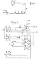
- Figure 1 makes it possible to understand the mechanical principle of the movement of the retractable cleaning brush 8 which comes into contact with a read head constituted by a magnetic cell 9, after each removal of the cassette from the support plate of the cassette player apparatus on which is mounted the cleaning device according to the invention.
- the stop 5, integral with the brush 8 is in contact with a position sensor such as a micro-contact 6.
- the brush 8 is then in a retracted position.
- the detection of the removal of a cassette then triggers the starting of the DC motor 1 which drives a belt 4 guided by idler pulleys 2 and 3 and capable of communicating a movement both to the brush 8 and to the stop 5 so as to bring the brush 8 into contact with the front face 91 of the read head 9 which is provided to cooperate with a magnetic strip.
- a second position sensor 7 such as a microswitch
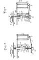
- FIGS. 3 and 4 show an exemplary embodiment in which the assembly of the cleaning device is arranged under a casing 90 above which the magnetic reading cell 9 is mounted.
- the cleaning device is mounted on a support 100 and comprises a brush 8 capable of passing through an opening 92 formed in the casing 90 to come into the working position (FIG. 4).
- the brush 8 which can be removable, is fixed to a rod 51 sliding in a guide piece 111 secured to the support 100.
- the rod 51 is extended at its rear part by a threaded rod 41 made integral, at its free end, d 'a receiving pulley 3 using a fixing part 3a.
- the pulley 3 is rotated by a belt 4 engaged on a pulley 2 which is itself integral with the output shaft of the motor 1 mounted on the support 100.
- the threaded rod 41 is engaged in a threaded hole 114 formed in a fixed part 113 mounted with an arm 112 on the support 100.
- the rotation drive of the pulley 3 thus makes it possible to communicate with the rod 51 and with the brush 8 not only a rotational movement on themselves, but also a movement controlled in advance in the axial direction of the rods 41, 51.
- the stop 5 integral with the rod 51 cooperates with the top and bottom limit switches 7 and 6 mounted on the support arm 112 on either side of the stop 5, in order to limit the stroke of the rod 51 and cause the reversal of the direction of operation of the motor 1 and therefore the direction of advance of the rod 51.
- FIG. 2 shown in solid line, the states of the micro-contacts 7 and 6 at the end of race when these are in the rest state, that is to say are not requested by the stopper 5.
- the state of the contacts 7 and 6 when these are touched by the stopper 5 is shown in broken lines.
- the contact 18 for detecting the presence of a cassette in the player-recorder device is shown in solid line in its rest state corresponding to the absence of cassette and in broken line in its state corresponding to the presence of a cassette in the unit.
- a relay 11 comprising a coil 11a and two movable contacts 11b, 11c makes it possible to reverse the polarity of the supply voltage at the terminals of the motor 1 in order to reverse the direction of rotation of the latter in the manner which will be explained more far.
- the reference numerals 21 to 38 denote the different connection terminals of the contacts 6,7,18 and llb, lic.
- the electronic control circuit cooperating with the various contacts and ensuring the operation of the relay 11 according to a predetermined sequence making it possible to carry out a round trip of the cleaning brush 8 each time a cassette is removed, can be achieved so particularly simple.
- a transistor 14 whose collector is connected by a resistor 15 to the power source, and the emitter is grounded, can deliver on its collector an output signal representative of the presence or absence of a cassette.
- the base of transistor 14 is connected to one end of a resistor 16, the other end of which is connected on the one hand to ground via a capacitor 13 and on the other hand to terminals 21. and 23 of the cassette presence contact 18.
- the terminal 24 of the contact 18 is itself connected via a resistor 17 to the positive pole of the motor supply 1.
- the terminal 22 of the contact 18 is itself connected to the terminals 26 and 27 of the contact 7 high limit switch.
- the terminal 28 of the contact 7 is connected to the end of the coil 11a not connected to earth and the terminal 25 of the contact 7 is connected to this same end of the coil via a diode 12.
- the terminals 29 and 38 of the bottom limit switch 6 and of the switch llb, 11c are connected to ground.
- the terminals 35 and 36 of the switch Ilb, llc are connected to the positive pole of the motor supply 1.
- the terminals 30 and 33 of the contact 6 and of the switch llb, 11c are connected together, and the terminals 34, 37 of the switch llb , llc are connected to motor 1.
- the operation of the circuit of FIG. 2 is as follows.
- the cassette presence contact 18 is in its position shown in dotted lines and connects the terminals 23 and 24.
- the positive supply voltage of the motor 1 (for example 12 volts) is then brought to the base of transistor 14 via resistors 17 and 16.
- the transistor 14 is saturated, the output on the collector is at OV and the capacitor 13 is charged.
- the cassette presence contact 18 returns between the terminals 21 and 22 in the position shown in Full line.
- the brush 8 is then in its low position, only the bottom limit switch 6 is in its activated position between terminals 31 and 32 while the top limit switch 7 is in its rest position between terminals 2 7 and 28.
- the capacitor 13 is thus placed in series with the coil 11a of the relay 11.
- the diode 12 discharges therein preventing direct return of the current to ground.
- the switch 11a, 11b then passes from its position shown in FIG. 2 to the position where the terminals 34 and 35 are connected by the contact 11c and the terminals 37 and 38 are connected by the contact 11b.
- the motor 1 is excited and drives the brush 8 so as to move the latter upwards.
- the stop 5 leaves contact 6 which is switched to its position shown in solid lines between terminals 29 and 30.
- the stop 5 When the brush 8 has arrived in its working position in contact with the surface 91 of the read head, the stop 5 also comes into contact with the top limit microswitch 7 which passes into its position shown in broken lines between terminals 25 and 26. Thanks to the direct connection between terminal 25 and earth, the input of the coil 11a is earthed and the contacts llb, 11c return to their initial position respectively between terminals 37 and 36 , and between terminals 34 and 33, in the position shown in FIG. 2. The direction of operation of the motor 1 is then reversed, and the brush descends to its initial position where the stop 5 comes into contact with the contact 6 and, causing it to pass this in its activated position shown in broken lines between terminals 31 and 32, disconnects the power supply to the motor.
- the system is then ready to operate again as soon as a cassette has been replaced in the device, which will recharge the capacitor 13, then removed from the device, which will re-trigger the movement of back and forth of the brush 8 by the return of the contact 18 in its position shown in solid lines.
- control system described above is thus particularly simple and robust and very inexpensive to manufacture, since the active elements are few.
- equivalent electronic circuits could be substituted for the assembly shown in FIG. 2 in order to obtain the same control sequence for motor 1.
Landscapes
- Nozzles For Electric Vacuum Cleaners (AREA)
- Supporting Of Heads In Record-Carrier Devices (AREA)
- Auxiliary Devices For Machine Tools (AREA)
- Automatic Analysis And Handling Materials Therefor (AREA)
- Cleaning In General (AREA)
- Accessory Devices And Overall Control Thereof (AREA)
Priority Applications (1)
| Application Number | Priority Date | Filing Date | Title |
|---|---|---|---|
| AT83401703T ATE25440T1 (de) | 1982-08-26 | 1983-08-24 | Automatische reinigungsvorrichtung eines lesekopfes eines kassettenaufnahmegeraetes. |
Applications Claiming Priority (2)
| Application Number | Priority Date | Filing Date | Title |
|---|---|---|---|
| FR8214663A FR2532459A1 (fr) | 1982-08-26 | 1982-08-26 | Dispositif de nettoyage automatique d'une tete de lecture d'appareil enregistreur a cassette |
| FR8214663 | 1982-08-26 |
Publications (2)
| Publication Number | Publication Date |
|---|---|
| EP0102897A1 true EP0102897A1 (de) | 1984-03-14 |
| EP0102897B1 EP0102897B1 (de) | 1987-02-04 |
Family
ID=9277072
Family Applications (1)
| Application Number | Title | Priority Date | Filing Date |
|---|---|---|---|
| EP83401703A Expired EP0102897B1 (de) | 1982-08-26 | 1983-08-24 | Automatische Reinigungsvorrichtung eines Lesekopfes eines Kassettenaufnahmegerätes |
Country Status (4)
| Country | Link |
|---|---|
| EP (1) | EP0102897B1 (de) |
| AT (1) | ATE25440T1 (de) |
| DE (1) | DE3369760D1 (de) |
| FR (1) | FR2532459A1 (de) |
Cited By (10)
| Publication number | Priority date | Publication date | Assignee | Title |
|---|---|---|---|---|
| GB2201027A (en) * | 1987-02-11 | 1988-08-17 | Pacevault Ltd | Apparatus for use in cleaning a tape head |
| AT395488B (de) * | 1991-03-18 | 1993-01-25 | Philips Nv | Geraet zum aufzeichnen und wiedergeben von signalen mit mindestens einem rotierenden magnetkopf |
| US5793580A (en) * | 1996-06-18 | 1998-08-11 | International Business Machines Corporation | Mechanically actuated head cleaner for magnetic tape drive |
| US6067211A (en) * | 1996-04-03 | 2000-05-23 | International Business Machines Corporation | Oscillating magnetic head and stationary brush cleaning apparatus |
| US6154341A (en) * | 1998-04-08 | 2000-11-28 | Storage Technology Corporation | System and method for accessing and cleaning a recording system |
| US6344947B1 (en) * | 1998-12-25 | 2002-02-05 | Nec Corporation | Head cleaner |
| EP1089260A3 (de) * | 1999-09-27 | 2002-08-28 | Nec Corporation | Magnetkopfreiniger |
| US6624960B1 (en) * | 2000-03-10 | 2003-09-23 | Exabyte Corporation | Current sensing drum/cleaning wheel positioning method and apparatus for magnetic storage system |
| GB2420656A (en) * | 2004-11-25 | 2006-05-31 | Mitsumi Electric Co Ltd | Recording and/or Reproducing Device Having A Positioning Arrangement For Positioning A Head Cleaning Brush |
| US7099101B2 (en) | 2004-11-01 | 2006-08-29 | International Business Machines Corporation | Apparatus, system, and method for determining contact with a magnetic head in a tape drive |
Citations (6)
| Publication number | Priority date | Publication date | Assignee | Title |
|---|---|---|---|---|
| BE678979A (de) * | 1965-04-28 | 1966-10-06 | ||
| US3595584A (en) * | 1965-05-17 | 1971-07-27 | Iit Res Inst | Transducer apparatus |
| US3636276A (en) * | 1969-11-26 | 1972-01-18 | Tenna Corp | Tape cartridge player transducer head cleaner |
| FR2227596A1 (de) * | 1973-04-28 | 1974-11-22 | Tokyo Shibaura Electric Co | |
| DE2423288A1 (de) * | 1974-05-14 | 1975-11-27 | Grundig Emv | Einrichtung an tonbandgeraeten |
| US3964104A (en) * | 1975-03-31 | 1976-06-15 | International Business Machines Corporation | Intermittent cleaner for rotating magnetic head |
Family Cites Families (1)
| Publication number | Priority date | Publication date | Assignee | Title |
|---|---|---|---|---|
| US3593584A (en) * | 1969-03-06 | 1971-07-20 | Solomon Jack | Automatic testing units for pipe fittings |
-
1982
- 1982-08-26 FR FR8214663A patent/FR2532459A1/fr not_active Withdrawn
-
1983
- 1983-08-24 DE DE8383401703T patent/DE3369760D1/de not_active Expired
- 1983-08-24 AT AT83401703T patent/ATE25440T1/de not_active IP Right Cessation
- 1983-08-24 EP EP83401703A patent/EP0102897B1/de not_active Expired
Patent Citations (6)
| Publication number | Priority date | Publication date | Assignee | Title |
|---|---|---|---|---|
| BE678979A (de) * | 1965-04-28 | 1966-10-06 | ||
| US3595584A (en) * | 1965-05-17 | 1971-07-27 | Iit Res Inst | Transducer apparatus |
| US3636276A (en) * | 1969-11-26 | 1972-01-18 | Tenna Corp | Tape cartridge player transducer head cleaner |
| FR2227596A1 (de) * | 1973-04-28 | 1974-11-22 | Tokyo Shibaura Electric Co | |
| DE2423288A1 (de) * | 1974-05-14 | 1975-11-27 | Grundig Emv | Einrichtung an tonbandgeraeten |
| US3964104A (en) * | 1975-03-31 | 1976-06-15 | International Business Machines Corporation | Intermittent cleaner for rotating magnetic head |
Cited By (11)
| Publication number | Priority date | Publication date | Assignee | Title |
|---|---|---|---|---|
| GB2201027A (en) * | 1987-02-11 | 1988-08-17 | Pacevault Ltd | Apparatus for use in cleaning a tape head |
| AT395488B (de) * | 1991-03-18 | 1993-01-25 | Philips Nv | Geraet zum aufzeichnen und wiedergeben von signalen mit mindestens einem rotierenden magnetkopf |
| US6067211A (en) * | 1996-04-03 | 2000-05-23 | International Business Machines Corporation | Oscillating magnetic head and stationary brush cleaning apparatus |
| US5793580A (en) * | 1996-06-18 | 1998-08-11 | International Business Machines Corporation | Mechanically actuated head cleaner for magnetic tape drive |
| US6154341A (en) * | 1998-04-08 | 2000-11-28 | Storage Technology Corporation | System and method for accessing and cleaning a recording system |
| US6344947B1 (en) * | 1998-12-25 | 2002-02-05 | Nec Corporation | Head cleaner |
| EP1089260A3 (de) * | 1999-09-27 | 2002-08-28 | Nec Corporation | Magnetkopfreiniger |
| US6624960B1 (en) * | 2000-03-10 | 2003-09-23 | Exabyte Corporation | Current sensing drum/cleaning wheel positioning method and apparatus for magnetic storage system |
| US7099101B2 (en) | 2004-11-01 | 2006-08-29 | International Business Machines Corporation | Apparatus, system, and method for determining contact with a magnetic head in a tape drive |
| GB2420656A (en) * | 2004-11-25 | 2006-05-31 | Mitsumi Electric Co Ltd | Recording and/or Reproducing Device Having A Positioning Arrangement For Positioning A Head Cleaning Brush |
| US7372668B2 (en) | 2004-11-25 | 2008-05-13 | Mitsumi Electric Co., Ltd. | Recording and/or reproducing device having a positioning arrangement for positioning a cleaning brush |
Also Published As
| Publication number | Publication date |
|---|---|
| FR2532459A1 (fr) | 1984-03-02 |
| ATE25440T1 (de) | 1987-02-15 |
| DE3369760D1 (en) | 1987-03-12 |
| EP0102897B1 (de) | 1987-02-04 |
Similar Documents
| Publication | Publication Date | Title |
|---|---|---|
| EP0102897B1 (de) | Automatische Reinigungsvorrichtung eines Lesekopfes eines Kassettenaufnahmegerätes | |
| FR2583595A1 (fr) | Dispositif de commande d'un moteur electrique a courant continu pour essuie-glace. | |
| CH626764A5 (de) | ||
| FR2525832A1 (fr) | Dispositif de commande d'un moteur electrique | |
| FR2587402A1 (fr) | Appareil pour detecter des informations relatives au deplacement d'une porte dans un systeme de porte automatique | |
| FR2732795A3 (fr) | Appareil d'analyse d'images a balayage, communement appele scanner | |
| FR2484118A1 (fr) | Dispositif pour rechercher une piste d'information desiree | |
| FR2483102A1 (fr) | Procede d'attouchement des contacts galvaniques d'un document d'identification comportant un module de circuit integre incorpore | |
| FR2777079A1 (fr) | Dispositif pour la detection de l'ouverture d'un compteur | |
| EP3794191B1 (de) | Griffvorrichtung für eine kraftfahrzeugtür mit optimisierter anschlusstechnik | |
| EP0099290B1 (de) | Hochisolierter automatischer Schalter mit wenig Leistungs- und Raumbedarf | |
| EP0502773B1 (de) | Steuerungsanordnung für einen Motor, insbesondere für den Antrieb von Aufzugstüren | |
| FR2460817A1 (fr) | Essuie-glace pour vehicule automobile | |
| US3599984A (en) | Automatic control device for record players | |
| FR2549232A1 (fr) | Perfectionnements aux dispositifs pour lire les quantites de charges electriques portees par un dielectrique | |
| EP0965724A1 (de) | Antriebsvorrichtung einer in zwei Richtungen drehbaren rohrförmigen Walze, Rolladenwalze mit einer derartigen Antriebsvorrichtung, Rolladen mit einer derartigen Walze | |
| FR2556843A1 (fr) | Appareil de localisation de defauts resistifs dans des boucles de guidage | |
| FR2513421A1 (fr) | Dispositif de recherche de la piste d'un signal d'information pour un appareil de reproduction de supports d'enregistrement tournants | |
| EP0531235B1 (de) | Anordnung zum Herausziehen eines Negativfilmendes aus einer Patrone | |
| EP0736961A1 (de) | Vorrichtung zur Winkelregelung eines Schrittmotors | |
| FR2498807A1 (fr) | Relais monostable a faible consommation | |
| FR2537760A1 (fr) | Mecanisme de protection de l'aiguille pour un tourne-videodisque | |
| FR2674701A1 (fr) | Dispositif de securite pour installations d'ouverture et de fermeture des portails a commande electrique et applications analogues. | |
| CH468054A (fr) | Dispositif d'arrêt automatique et de mise hors position opérative de la cassette, pour appareil d'enregistrement et de reproduction d'information, notamment de fréquences sonores, sur un support en forme de bande | |
| FR2848971A1 (fr) | Dispositif de commande electrique d'un frein de parking pour vehicule automobile |
Legal Events
| Date | Code | Title | Description |
|---|---|---|---|
| PUAI | Public reference made under article 153(3) epc to a published international application that has entered the european phase |
Free format text: ORIGINAL CODE: 0009012 |
|
| AK | Designated contracting states |
Designated state(s): AT BE CH DE GB IT LI LU NL SE |
|
| 17P | Request for examination filed |
Effective date: 19840524 |
|
| GRAA | (expected) grant |
Free format text: ORIGINAL CODE: 0009210 |
|
| AK | Designated contracting states |
Kind code of ref document: B1 Designated state(s): AT BE CH DE GB IT LI LU NL SE |
|
| PG25 | Lapsed in a contracting state [announced via postgrant information from national office to epo] |
Ref country code: NL Effective date: 19870204 Ref country code: IT Free format text: LAPSE BECAUSE OF FAILURE TO SUBMIT A TRANSLATION OF THE DESCRIPTION OR TO PAY THE FEE WITHIN THE PRESCRIBED TIME-LIMIT;WARNING: LAPSES OF ITALIAN PATENTS WITH EFFECTIVE DATE BEFORE 2007 MAY HAVE OCCURRED AT ANY TIME BEFORE 2007. THE CORRECT EFFECTIVE DATE MAY BE DIFFERENT FROM THE ONE RECORDED. Effective date: 19870204 Ref country code: AT Effective date: 19870204 |
|
| REF | Corresponds to: |
Ref document number: 25440 Country of ref document: AT Date of ref document: 19870215 Kind code of ref document: T |
|
| PG25 | Lapsed in a contracting state [announced via postgrant information from national office to epo] |
Ref country code: SE Effective date: 19870228 |
|
| REF | Corresponds to: |
Ref document number: 3369760 Country of ref document: DE Date of ref document: 19870312 |
|
| NLV1 | Nl: lapsed or annulled due to failure to fulfill the requirements of art. 29p and 29m of the patents act | ||
| PG25 | Lapsed in a contracting state [announced via postgrant information from national office to epo] |
Ref country code: LU Free format text: LAPSE BECAUSE OF NON-PAYMENT OF DUE FEES Effective date: 19870831 Ref country code: LI Effective date: 19870831 Ref country code: CH Effective date: 19870831 |
|
| PLBE | No opposition filed within time limit |
Free format text: ORIGINAL CODE: 0009261 |
|
| STAA | Information on the status of an ep patent application or granted ep patent |
Free format text: STATUS: NO OPPOSITION FILED WITHIN TIME LIMIT |
|
| 26N | No opposition filed | ||
| BERE | Be: lapsed |
Owner name: GROUPEMENT D'INTERET ECONOMIQUE MEDILEC GIE. Effective date: 19870831 |
|
| REG | Reference to a national code |
Ref country code: CH Ref legal event code: PL |
|
| PG25 | Lapsed in a contracting state [announced via postgrant information from national office to epo] |
Ref country code: DE Effective date: 19880503 |
|
| GBPC | Gb: european patent ceased through non-payment of renewal fee | ||
| PG25 | Lapsed in a contracting state [announced via postgrant information from national office to epo] |
Ref country code: GB Free format text: LAPSE BECAUSE OF NON-PAYMENT OF DUE FEES Effective date: 19881122 |
|
| PG25 | Lapsed in a contracting state [announced via postgrant information from national office to epo] |
Ref country code: BE Effective date: 19890831 |