EP0102999B1 - Verfahren und einrichtung für das maschinelle verlegen von pflastersteinen - Google Patents
Verfahren und einrichtung für das maschinelle verlegen von pflastersteinen Download PDFInfo
- Publication number
- EP0102999B1 EP0102999B1 EP19830900976 EP83900976A EP0102999B1 EP 0102999 B1 EP0102999 B1 EP 0102999B1 EP 19830900976 EP19830900976 EP 19830900976 EP 83900976 A EP83900976 A EP 83900976A EP 0102999 B1 EP0102999 B1 EP 0102999B1
- Authority
- EP
- European Patent Office
- Prior art keywords
- bricks
- guide
- frame
- suction
- pattern
- Prior art date
- Legal status (The legal status is an assumption and is not a legal conclusion. Google has not performed a legal analysis and makes no representation as to the accuracy of the status listed.)
- Expired
Links
- 238000000034 method Methods 0.000 title claims abstract description 8
- 239000011449 brick Substances 0.000 claims abstract description 46
- 230000008878 coupling Effects 0.000 claims description 11
- 238000010168 coupling process Methods 0.000 claims description 11
- 238000005859 coupling reaction Methods 0.000 claims description 11
- 210000002445 nipple Anatomy 0.000 claims description 6
- 239000011456 concrete brick Substances 0.000 description 2
- 238000007792 addition Methods 0.000 description 1
- 238000010276 construction Methods 0.000 description 1
Images



Classifications
-
- E—FIXED CONSTRUCTIONS
- E01—CONSTRUCTION OF ROADS, RAILWAYS, OR BRIDGES
- E01C—CONSTRUCTION OF, OR SURFACES FOR, ROADS, SPORTS GROUNDS, OR THE LIKE; MACHINES OR AUXILIARY TOOLS FOR CONSTRUCTION OR REPAIR
- E01C19/00—Machines, tools or auxiliary devices for preparing or distributing paving materials, for working the placed materials, or for forming, consolidating, or finishing the paving
- E01C19/52—Apparatus for laying individual preformed surfacing elements, e.g. kerbstones
- E01C19/524—Apparatus for laying individual preformed surfacing elements, e.g. kerbstones using suction devices
Definitions
- the invention relates to a method of mechanically laying paving or the like, in which bricks are taken simultaneously from a packet of bricks, in batches of at least one group at a time, and placed in a desired pattern as they are moved to a sub-grade; wherein two or more rows of bricks may be removed at a time from the upper layer of a stack of bricks positioned in a first pattern, the bricks of the group of bricks after being removed from the packet are first spaced a small distance apart, then moved into the desired basic pattern, thereafter moved towards each other again and subsequently put in their place on the sub-grade.
- a method of a kind mentioned above is characterized by engaging the bricks of these rows each individually and simultaneously, then putting them into the desired second pattern and placing them all at the same time directly onto the sub-grade in said second pattern. In this way it is possible to prepare paving with the bricks in so-called herringbone pattern.
- the invention further relates to an apparatus for carrying out the before described method, comprising a carriage equipped with suction-lift means comprising a frame equipped with at least one suction cup which is connected with a vacuum source, wherein the frame is equipped with a plurality of suction cups corresponding with the number of bricks to be placed simultaneously, which suction cups are movable in longitudinal and transverse direction.
- the apparatus is characterized in that the suction cups also in a rotary sense are in mutually coupled fashion.
- Swiss patent 348,919 describes a movable lifting and transporting apparatus by means of which bricks can be transported along the track of the transporting apparatus. To this effect, the apparatus comprises a plurality of juxtaposed suction heads. However, further similarities with the invention are lacking.
- German Offenlegungsschrift 2,918,232 shows and describes an apparatus for laying profiled concrete bricks.
- the bricks of each row can be displaced relatively to each adjacent row.
- the apparatus comprises a parallelogram- shaped pivotal lever system, thus creating the possibility of having the spacing apart and the movement into the desired basic pattern and the movement towards each other take place simultaneously.
- each suction cup is secured to a hollow guide bush or a suction pipe extending through it, the bushes are accommodated, in groups, for sliding movement in relatively movable guides, each guide bush is fixed to a guide plate, and the guide plates which are fixed to one and the same guide are interconnected by two slotted coupling elements disposed diametrically relatively to the guide bush.
- the guides may each, with the help of sliding bearings, be connected with shafts disposed on opposite sides of the frame, and cylinder and piston combinations are mounted between the guides.
- one of the guide bushes of each set cooperating with one guide may be connected to the free end of the piston rod so as to be restrained from rotation and the guide plate located opposite the piston rod end may be engaged by a spring, on the one hand, and by a coupling plate, on the other, the other end of each of which is fixed to the frame.
- the frame may be provided with a vacuum tank, which, on the one hand, can be connected with a vacuum source and, on the other hand, is provided with a number of connecting nipples corresponding to the number of hollow guide bushes, which connecting nipples are each fixed, by means of vacuum tubes, to a hollow guide bush or a suction pipe extending through it. It is thus achieved that the apparatus operates correctly even in case one or more bricks are missing by whatever cause.
- each guide may consist of two pairs of strips in spaced superimposed relationship, with the guide plates being each attached between the two lower and upper strips.
- Fig. 1 which shows a top view of a stack of bricks
- bricks 1 are supplied in a number of rows, in this example four, of eleven bricks each. From the closed pattern shown in Fig. 1 a the rows are spaced a small distance apart (Fig. 1b). As Fig. 1c shows, the bricks of each row are then spaced a small distance apart, at the same time the bricks of adjoining rows are put in an off-set position relative to each other. Then all the bricks are turned, that is to say: each of the successive rows alternately in opposite direction (Fig. 1d).
- Figures 2a, 2b, 2c and 2d successively show the positions of the bricks when moved from the closed pattern in which they are supplied to the off-set pattern shown in Fig. 2d.
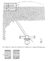
- FIGs 3-7 For mechanically laying paving the apparatus shown in Figures 3-7 may be used.
- jib 2 of a travelling crane 3 is shown.
- These two figures show that from the stack of bricks 4, supplied, by means of a suction-lift device 5 carried by the free end of jib 2, the upper layer can be taken from the stack of bricks 4. After placing the bricks in the correct pattern these can be placed in the pavement simultaneously.
- the suction-lift device 5 will now be described in more detail with reference to Figures 5, 6 and 7. These show that the suction-lift device is provided with a frame 6. In this frame two parallel shafts are secured one above the other at both sides.
- each brick is engaged separately by a suction cup 8.
- Each of the suction cups is secured to a suction pipe 9 extending through a guide bush 10 which in turn is secured to a guide plate 11.
- the drawing shows that the guide bushes are mounted in a guide consisting of four spaced strips 12, 13, 14 and 15 for cooperation with the suction cups for engaging a single row of bricks.
- the ends of strips 12-15 are each attached, by means of couplings, to sliding bearings 17 mounted on shaft 7.
- Guide bushes 10 are each positioned for sliding movement between strips 12, 14, on the one hand, and strips 13, 15, on the other, while guide plates 11, fixed to guide bushes 10, are positioned for sliding movement between strips 12, 13, on the one hand, and strips 14, 15, on the other.
- the adjoining guide plates 11, fixed to guide bushes cooperating with one guide are each interconnected by two pairs of coupling strips 18.
- the coupling strips, each engaging with each guide plate diametrically opposite the guide bush, are at one end equipped with a slot 19.
- the coupling plate 11 located on one end of a row is secured to coupling 16 by a spring 20, on the one hand, and by a coupling rod 21, on the other.
- a piston-and-cylinder assembly 22 is used for realizing the desired movement pattern.
- the free end of piston rod 23 thereof is, by means of a strip 24, fixed to one of the guide bushes 10 cooperating with one guide 12-15.
- For the spacing apart of guides 12-15 during the execution of the desired movement pattern these are each interconnected by piston-and-cylinder combinations 25 on the position of couplings 16.
- FIGS 5 and 7 show a vacuum tank 26, arranged within frame 6 of the suction-lift device, which tank is provided with a number of connecting nipples 27 corresponding with the number of guide plates. Connecting nipples 27 are each, by means of vacuum tubes 28, connected with a suction pipe 9. Although not shown in the drawing, it will be clear that the vacuum tank may be connected with a vacuum pump fixed to carriage 3, by means of a tube.
- the drawing shows that the top of the frame is provided with a connecting flange 29 for attachment to the movable jib 2 of crane 3.
- a servo motor not shown may be built in for selectively turning the frame of the suction-lift device, so that the position thereof may be adapted to the position of the stack of bricks from which the upper layer or part thereof is to be removed and for placing the same on the exact position in the pavement pattern.
- the construction of the guides and the mutual connection of the guide plate could easily be changed.
- such as clamping means could be provide to ensure that the rows of bricks to be engaged are held properly in contact with each other, so that each suction cup engage with the subjacent bricks approximately in the middle.
- the apparatus lends itself particularly well to placing smaller zones than the four or eleven bricks placed in this case, namely by covering some of the suction cups or closing them in some other way. Also the suction cup located in a fully enclosed corner can be closed, and the remaining brick, which is apt to give trouble during mechanical placing, may be manually put in its place afterwards.
Landscapes
- Engineering & Computer Science (AREA)
- Architecture (AREA)
- Civil Engineering (AREA)
- Structural Engineering (AREA)
- Road Paving Machines (AREA)
- Road Paving Structures (AREA)
Claims (8)
Priority Applications (1)
| Application Number | Priority Date | Filing Date | Title |
|---|---|---|---|
| AT83900976T ATE20609T1 (de) | 1982-03-17 | 1983-03-17 | Verfahren und einrichtung fuer das maschinelle verlegen von pflastersteinen. |
Applications Claiming Priority (2)
| Application Number | Priority Date | Filing Date | Title |
|---|---|---|---|
| NL8201109A NL8201109A (nl) | 1982-03-17 | 1982-03-17 | Werkwijze en inrichting voor het mechanisch leggen van een bestrating. |
| NL8201109 | 1982-03-17 |
Publications (2)
| Publication Number | Publication Date |
|---|---|
| EP0102999A1 EP0102999A1 (de) | 1984-03-21 |
| EP0102999B1 true EP0102999B1 (de) | 1986-07-02 |
Family
ID=19839431
Family Applications (1)
| Application Number | Title | Priority Date | Filing Date |
|---|---|---|---|
| EP19830900976 Expired EP0102999B1 (de) | 1982-03-17 | 1983-03-17 | Verfahren und einrichtung für das maschinelle verlegen von pflastersteinen |
Country Status (4)
| Country | Link |
|---|---|
| EP (1) | EP0102999B1 (de) |
| DE (1) | DE3364324D1 (de) |
| NL (1) | NL8201109A (de) |
| WO (1) | WO1983003270A1 (de) |
Families Citing this family (11)
| Publication number | Priority date | Publication date | Assignee | Title |
|---|---|---|---|---|
| DE3339115A1 (de) * | 1983-10-28 | 1985-05-15 | Hubert 4250 Bottrop Schnieder | Vorrichtung zum verlegen von pflastersteinen |
| NL8401469A (nl) * | 1984-05-08 | 1985-12-02 | Arend Luijten | Werkwijze voor het mechanisch leggen van stenen in keperverband, en een inrichting daarvoor. |
| NL193667C (nl) * | 1986-04-01 | 2000-06-06 | Luijten Arend | Werkwijze voor het mechanisch leggen van stenen in keperverband. |
| NL8602475A (nl) * | 1986-10-01 | 1988-05-02 | Stramech Bv | Werkwijze en inrichting voor het leggen van een wegdek benevens een heftoestel ten gebruike daarbij. |
| FR2673436B1 (fr) * | 1991-02-28 | 1995-06-09 | Bouquet Luc | Procede et dispositif de pose de revetement de sol au moyen de dalles. |
| NL9301484A (nl) * | 1993-08-27 | 1995-03-16 | Arend Luijten | Werkwijze en inrichting voor het omvormen van lagen straatstenen van een gelijkgericht, uitgangsverband naar een gekeperd legverband. |
| NL1009689C2 (nl) * | 1998-07-17 | 2000-01-18 | Theodorus Johannes Adrianus Br | Inrichting voor het verplaatsen van stenen. |
| AU782672B2 (en) * | 1999-12-24 | 2005-08-18 | Robert Darryl Peak | An improved method of providing a paved surface |
| NL2000945C2 (nl) * | 2007-10-18 | 2009-04-21 | Sijnja Konstruktie B V | Stenenlegger. |
| NL1035850C (nl) * | 2008-08-20 | 2010-03-10 | Machf De Oude Rijn Pannerden B V | Systeem, opneeminrichting alsmede werkwijze voor het vormen van pakketten stenen die gebruikt worden voor machinaal straten. |
| NL2006785C2 (nl) * | 2011-05-16 | 2012-11-19 | Kalkman Holding B V | Werkwijze voor het omformeren van langwerpige straatstenen. |
Family Cites Families (9)
| Publication number | Priority date | Publication date | Assignee | Title |
|---|---|---|---|---|
| BE562009A (de) * | 1956-05-15 | |||
| BE702151A (de) * | 1964-12-29 | 1968-02-01 | ||
| NL6903959A (de) * | 1969-03-14 | 1970-09-16 | ||
| NL147811B (nl) * | 1972-06-13 | 1975-11-17 | Ver Fab Beton Straatstenen | Werkwijze en inrichting voor het groepsgewijs in een wegdek plaatsen van bestratingsstenen. |
| NL7215130A (de) * | 1972-11-08 | 1974-05-10 | ||
| DE2718066A1 (de) * | 1977-04-22 | 1978-11-02 | Barth Kg Dr | Verfahren und vorrichtung zum maschinellen belegen eines untergrundes mit pflastersteinen |
| DE2753972C2 (de) * | 1977-12-03 | 1986-09-04 | Oldenburger Betonsteinwerke Gmbh, 2906 Wardenburg | Verfahren zum Klammern und Ausrichten einer einen Verband der Steine aufweisenden Verlegeeinheit aus einer Lage von Betonsteinen mit Verbundelementen und Vorrichtung zur Durchführung des Verfahrens |
| DE2823233A1 (de) * | 1978-05-27 | 1979-11-29 | Lehnen Axel Holger Vermietung | Verfahren und vorrichtung zum lagenweisen zusammenfassen von beton-pflastersteinen zu einer laeuferverband der pflastersteine aufweisenden, als verlegeeinheit nutzbaren steinscheibe |
| DE2918232C2 (de) * | 1979-05-05 | 1982-11-11 | Oldenburger Betonsteinwerke Gmbh, 2906 Wardenburg | Greifer zum Klammern und Ausrichten einer Lage von Beton-Pflastersteinen aus Verbundelementen zu einer einen Läuferverband der Steine aufweisenden Verlegeeinheit |
-
1982
- 1982-03-17 NL NL8201109A patent/NL8201109A/nl not_active Application Discontinuation
-
1983
- 1983-03-17 WO PCT/NL1983/000011 patent/WO1983003270A1/en not_active Ceased
- 1983-03-17 EP EP19830900976 patent/EP0102999B1/de not_active Expired
- 1983-03-17 DE DE8383900976T patent/DE3364324D1/de not_active Expired
Also Published As
| Publication number | Publication date |
|---|---|
| DE3364324D1 (en) | 1986-08-07 |
| EP0102999A1 (de) | 1984-03-21 |
| NL8201109A (nl) | 1983-10-17 |
| WO1983003270A1 (en) | 1983-09-29 |
Similar Documents
| Publication | Publication Date | Title |
|---|---|---|
| DE69420616T2 (de) | Aufnahme- und Fördereinheit für Stapel von Zuschnitten | |
| US4515264A (en) | Assembly line | |
| KR0130193B1 (ko) | 평평한 작업편의 조작 및 방향 설정장치 | |
| US4547115A (en) | Apparatus for transporting and aligning panel-like members | |
| DE2008457B2 (de) | Fertigungsanlage für die Herstellung von Platten, Trägern u.dgl. aus Stahlbeton | |
| EP0453407A1 (de) | Verfahren und Vorrichtung zur Bildung von Gruppen von Nahrungsmittelscheiben | |
| US4067766A (en) | Automatic building block laying panel-forming machine and method | |
| EP0102999A1 (de) | Verfahren und einrichtung für das maschinelle verlegen von pflastersteinen. | |
| US3927454A (en) | Apparatus for producing laminated magnetic cores for inductive electric apparatus | |
| DE2936472C2 (de) | Verlegeverfahren für aus Verbundsteinen gebildete Verlegeeinheiten und Klemmgreifer zur Durchführung des Verfahrens | |
| US4849062A (en) | Machine for forming a flat stack of sheets of predetermined format | |
| US4609137A (en) | Unit for assembly of a motor vehicle body element | |
| JP2521316B2 (ja) | コンクリ―トパネルの搬送装置 | |
| US4274781A (en) | Method and apparatus for packing timber | |
| US3013648A (en) | Block stacking machine | |
| CZ289071B6 (cs) | Způsob a zařízení pro vzájemné oddálení řad obdélníkových plastických pórobetonových těles | |
| US4831718A (en) | Process for laminating plate packs, in particular transformer cores | |
| US20170342667A1 (en) | Construction of a synthetic grass playing fields by flooring panels | |
| EP0184563A1 (de) | Vorrichtung zum Schichten von Magnetkernen für Transformatoren und dgl. | |
| EP1209290A1 (de) | Pflastervorrichtung | |
| DE60200668T2 (de) | Vorrichtung zum Be- und Entladen von Rollenpaletten für Fliesen | |
| US4961683A (en) | Device for aligning and lifting blocks in kiln cars | |
| US3875660A (en) | Method of producing laminated magnetic cores for inductive electric apparatus | |
| CN211140793U (zh) | 搬运装置和检测系统 | |
| US3951275A (en) | Block cubing assembly particularly for concrete blocks |
Legal Events
| Date | Code | Title | Description |
|---|---|---|---|
| PUAI | Public reference made under article 153(3) epc to a published international application that has entered the european phase |
Free format text: ORIGINAL CODE: 0009012 |
|
| AK | Designated contracting states |
Designated state(s): AT BE CH DE FR GB LI LU NL SE |
|
| 17P | Request for examination filed |
Effective date: 19840328 |
|
| GRAA | (expected) grant |
Free format text: ORIGINAL CODE: 0009210 |
|
| AK | Designated contracting states |
Kind code of ref document: B1 Designated state(s): AT BE CH DE FR GB LI LU NL SE |
|
| REF | Corresponds to: |
Ref document number: 20609 Country of ref document: AT Date of ref document: 19860715 Kind code of ref document: T |
|
| REF | Corresponds to: |
Ref document number: 3364324 Country of ref document: DE Date of ref document: 19860807 |
|
| ET | Fr: translation filed | ||
| PLBE | No opposition filed within time limit |
Free format text: ORIGINAL CODE: 0009261 |
|
| STAA | Information on the status of an ep patent application or granted ep patent |
Free format text: STATUS: NO OPPOSITION FILED WITHIN TIME LIMIT |
|
| 26N | No opposition filed | ||
| PGFP | Annual fee paid to national office [announced via postgrant information from national office to epo] |
Ref country code: LU Payment date: 19910206 Year of fee payment: 9 |
|
| PGFP | Annual fee paid to national office [announced via postgrant information from national office to epo] |
Ref country code: SE Payment date: 19910211 Year of fee payment: 9 |
|
| PGFP | Annual fee paid to national office [announced via postgrant information from national office to epo] |
Ref country code: GB Payment date: 19910305 Year of fee payment: 9 Ref country code: AT Payment date: 19910305 Year of fee payment: 9 |
|
| PGFP | Annual fee paid to national office [announced via postgrant information from national office to epo] |
Ref country code: CH Payment date: 19910307 Year of fee payment: 9 |
|
| PGFP | Annual fee paid to national office [announced via postgrant information from national office to epo] |
Ref country code: FR Payment date: 19910321 Year of fee payment: 9 |
|
| EPTA | Lu: last paid annual fee | ||
| PG25 | Lapsed in a contracting state [announced via postgrant information from national office to epo] |
Ref country code: LU Free format text: LAPSE BECAUSE OF NON-PAYMENT OF DUE FEES Effective date: 19920317 Ref country code: GB Effective date: 19920317 Ref country code: AT Effective date: 19920317 |
|
| PG25 | Lapsed in a contracting state [announced via postgrant information from national office to epo] |
Ref country code: SE Effective date: 19920318 |
|
| PGFP | Annual fee paid to national office [announced via postgrant information from national office to epo] |
Ref country code: DE Payment date: 19920326 Year of fee payment: 10 |
|
| PGFP | Annual fee paid to national office [announced via postgrant information from national office to epo] |
Ref country code: BE Payment date: 19920330 Year of fee payment: 10 |
|
| PG25 | Lapsed in a contracting state [announced via postgrant information from national office to epo] |
Ref country code: LI Effective date: 19920331 Ref country code: CH Effective date: 19920331 |
|
| PGFP | Annual fee paid to national office [announced via postgrant information from national office to epo] |
Ref country code: NL Payment date: 19920331 Year of fee payment: 10 |
|
| GBPC | Gb: european patent ceased through non-payment of renewal fee | ||
| PG25 | Lapsed in a contracting state [announced via postgrant information from national office to epo] |
Ref country code: FR Effective date: 19921130 |
|
| REG | Reference to a national code |
Ref country code: CH Ref legal event code: PL |
|
| REG | Reference to a national code |
Ref country code: FR Ref legal event code: ST |
|
| PG25 | Lapsed in a contracting state [announced via postgrant information from national office to epo] |
Ref country code: BE Effective date: 19930331 |
|
| BERE | Be: lapsed |
Owner name: MACHINEFABRIEK VERHEIJEN B.V. Effective date: 19930331 |
|
| PG25 | Lapsed in a contracting state [announced via postgrant information from national office to epo] |
Ref country code: NL Effective date: 19931001 |
|
| NLV4 | Nl: lapsed or anulled due to non-payment of the annual fee | ||
| PG25 | Lapsed in a contracting state [announced via postgrant information from national office to epo] |
Ref country code: DE Effective date: 19931201 |
|
| EUG | Se: european patent has lapsed |
Ref document number: 83900976.8 Effective date: 19921005 |