EP0103033A1 - Dispositif pour reporter des mailles d'aiguilles à des métiers rectilignes - Google Patents
Dispositif pour reporter des mailles d'aiguilles à des métiers rectilignes Download PDFInfo
- Publication number
- EP0103033A1 EP0103033A1 EP82108323A EP82108323A EP0103033A1 EP 0103033 A1 EP0103033 A1 EP 0103033A1 EP 82108323 A EP82108323 A EP 82108323A EP 82108323 A EP82108323 A EP 82108323A EP 0103033 A1 EP0103033 A1 EP 0103033A1
- Authority
- EP
- European Patent Office
- Prior art keywords
- needle bed
- neck
- combs
- finger
- needle
- Prior art date
- Legal status (The legal status is an assumption and is not a legal conclusion. Google has not performed a legal analysis and makes no representation as to the accuracy of the status listed.)
- Ceased
Links
- 238000009940 knitting Methods 0.000 title claims abstract description 12
- 210000001520 comb Anatomy 0.000 claims abstract description 43
- 238000006073 displacement reaction Methods 0.000 claims description 10
- 238000007373 indentation Methods 0.000 claims description 2
- 238000000034 method Methods 0.000 description 3
- 230000008569 process Effects 0.000 description 3
- RYGMFSIKBFXOCR-UHFFFAOYSA-N Copper Chemical compound [Cu] RYGMFSIKBFXOCR-UHFFFAOYSA-N 0.000 description 2
- 239000004744 fabric Substances 0.000 description 2
- 239000002184 metal Substances 0.000 description 2
- 229910052751 metal Inorganic materials 0.000 description 2
- 239000007769 metal material Substances 0.000 description 2
- 230000009467 reduction Effects 0.000 description 2
- 101100453960 Drosophila melanogaster klar gene Proteins 0.000 description 1
- 206010015535 Euphoric mood Diseases 0.000 description 1
- 230000009471 action Effects 0.000 description 1
- 230000008859 change Effects 0.000 description 1
- 238000003776 cleavage reaction Methods 0.000 description 1
- 238000010276 construction Methods 0.000 description 1
- 229910052802 copper Inorganic materials 0.000 description 1
- 239000010949 copper Substances 0.000 description 1
- 230000003247 decreasing effect Effects 0.000 description 1
- 230000005484 gravity Effects 0.000 description 1
- 238000004519 manufacturing process Methods 0.000 description 1
- 230000007246 mechanism Effects 0.000 description 1
- 238000011946 reduction process Methods 0.000 description 1
- 230000007017 scission Effects 0.000 description 1
Images
Classifications
-
- D—TEXTILES; PAPER
- D04—BRAIDING; LACE-MAKING; KNITTING; TRIMMINGS; NON-WOVEN FABRICS
- D04B—KNITTING
- D04B15/00—Details of, or auxiliary devices incorporated in, weft knitting machines, restricted to machines of this kind
- D04B15/02—Loop-transfer points
-
- D—TEXTILES; PAPER
- D04—BRAIDING; LACE-MAKING; KNITTING; TRIMMINGS; NON-WOVEN FABRICS
- D04B—KNITTING
- D04B15/00—Details of, or auxiliary devices incorporated in, weft knitting machines, restricted to machines of this kind
- D04B15/32—Cam systems or assemblies for operating knitting instruments
- D04B15/36—Cam systems or assemblies for operating knitting instruments for flat-bed knitting machines
- D04B15/362—Cam systems or assemblies for operating knitting instruments for flat-bed knitting machines with two needle beds in V-formation
- D04B15/365—Cam systems or assemblies for operating knitting instruments for flat-bed knitting machines with two needle beds in V-formation with provision for loop transfer from one needle bed to the other
-
- D—TEXTILES; PAPER
- D04—BRAIDING; LACE-MAKING; KNITTING; TRIMMINGS; NON-WOVEN FABRICS
- D04B—KNITTING
- D04B7/00—Flat-bed knitting machines with independently-movable needles
- D04B7/10—Flat-bed knitting machines with independently-movable needles with provision for narrowing or widening to produce fully-fashioned goods
-
- D—TEXTILES; PAPER
- D04—BRAIDING; LACE-MAKING; KNITTING; TRIMMINGS; NON-WOVEN FABRICS
- D04B—KNITTING
- D04B7/00—Flat-bed knitting machines with independently-movable needles
- D04B7/20—Flat-bed knitting machines with independently-movable needles with provision for changing the fabric construction, e.g. from plain to rib-loop fabric
Definitions
- the invention relates to a device for transferring needle stitches in flat knitting machines, in particular when the knitwear width is reduced or increased.
- the stitch-transfer device according to the invention should have a particularly simple construction and a safe mode of operation.
- the two neck combs are displaceable in their longitudinal direction independently of one another, they can be selected with their neck fingers as desired for the stitching and accordingly in Stitch delivery position raised needles are set, even if they are asymmetrical to the center of the needle bed.
- the two, swung-over neck combs are then advanced together in the direction of the needle bed, their neck fingers, which lie opposite the needles raised in the stitch-dispensing position, reaching through the loops carried by these needles.
- the raised needles are then lowered and thereby transfer their stitches to the neck fingers.
- the two neck combs are then swiveled up, thereby lifted out of the needle bed and then adjusted with their stitch-carrying neck fingers with respect to the needles which are still lowered and which are supposed to take up the neck-and-loop stitches.
- the neck combs are then pivoted away and advanced towards the needle bed so far that the stitches they carry come to lie in the path of movement of the needles intended to take up the stitches. Then these needles are driven out and remove the stitches from the shoulder fingers.
- the swung neck combs are then pulled back from the needle bed into their starting position, in which a new stitching can be initiated.
- the movements of the neck combs of the mesh neck device according to the invention can be achieved with the aid of any guide and drive means.
- An embodiment with a particularly simple structure and trouble-free mode of operation can be achieved in a further development of the inventive idea by the two capes Combs are slidably mounted in their longitudinal direction in a common slide which is movable transversely to the capes from and to the needle bed and is supported by a guide which extends over the length of the needle bed and which is pivotable up and down about a pivot axis parallel to the needle bed.
- each shoulder finger consists of two finger halves lying vertically next to one another and punched out of sheet metal material and which are releasably clamped between the strips forming the comb body with their rear ends facing away from the needle bed.
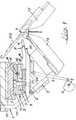
- FA and FP are the two needle beds of a two-contour flat knitting machine which are inclined towards each other in a roof shape and with the associated latch needles AT1 and AT2.
- this flat knitting machine reductions and increases in a manner known per se can only be achieved by moving the needle stitches of one e.g. of the rear needle bed FP, regardless of whether the knitted fabric is produced with the aid of a single needle bed or with the aid of the two needle beds FA, FP.
- the stitch transfer device according to the invention used in the exemplary embodiment shown as a reducing and increasing device is arranged, for example, over the front needle bed FA and interacts with the opposite, ie rear, needle bed FP.
- This guide 1 consists of an upper guide bar 101 and attached lower guide brackets 201 and is pivotally mounted on a machine frame 3 up and down about a pivot axis 2 parallel to the needle bed FA or FP.
- the guide 1 is supported on an underlying stop bar 4.
- the stop bar 4 is pivotally mounted on the machine frame 3 about an axis 104 parallel to the pivot axis 2 of the guide 1 and is firmly connected at one end to a lever arm 5 which cooperates with a cam disk 6 fastened on the shaft 7.
- 1, 4 and 5 shown in full lines, swiveled, approximately horizontal angular position of the stop bar 4, the guide 1 supported thereon also assumes its swiveled position.
- the stop bar 4 is pivoted upward about the pivot axis 104 with the aid of the cam 6 and the lever arm 5, it also lifts the guide 1 into its position pivoted upward about the pivot axis 2, as shown in broken lines in FIG. 4.
- a slide 8 is mounted in the guide 1, which extends parallel to the needle bed FP along its length and can be moved transversely to its longitudinal direction from and to the needle bed FP.
- the carriage 8 is mounted suspended on the underside of the guide bar 101 with the aid of a transverse dovetail guide or the like.
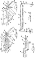
- a rocker arm 18 is pivotally mounted in the machine frame about an axis 19 parallel to the needle bed FP, as is shown in particular in FIG. 2.
- One end of this rocker arm 18 interacts with a cam disk 20 fastened on the shaft 7, while a driver pin 17, which projects laterally from the relevant end of the slide 8, engages in the other fork-shaped end of the rocker arm 18.
- neck combs 9 and 9 'are mounted for longitudinal displacement.
- each individual neck comb 9 or 9 takes place with the aid of a drum curve 23, in which one end of a rocker arm 21 engages.
- the same drive arrangement is of course also provided for the other neck comb 9 'on the right in FIG. 2, but is not shown in the drawing.
- the articulated connection between the rocker arm 21 and the associated neck comb 9 is required in order to enable the transverse displacement of the neck combs 9, 9 'directed to and from the needle bed FP together with the carriage 8.
- the intermediate joint piece 24 can be replaced by any other joint connection.
- each needle AT2 of the needle bed FP or every second or third needle AT2 of the needle bed FP can be assigned a transfer finger P of the relevant transfer comb 9 or 9 '.
- the neck fingers P of the two neck combs 9 and 9 ' can only be used in certain areas e.g. be provided at the end regions of the needle bed FP and be assigned to each individual needle AT2 or every second or third needle AT2 in these regions.
- each neck comb 9 and 9 ' consists of two superimposed comb strips 11 and 12, which are firmly connected to one another by means of screws 13, between which the individual ones Neck fingers P are releasably clamped with their rear ends, ie ends remote from the needle bed FP.
- the two finger halves P1 and P2 each have a V-shaped notch'10 in the upper edge of their rear ends.
- a continuous, V-shaped groove 14 is provided in the underside of the overlying comb strip 12.
- a wire 15 made of relatively easily deformable metal, such as copper or plastic with similar strength or elastic properties.
- the rear ends of the shoulder fingers P or the finger halves P1, P2 are pressed between the two comb strips 11 and 12 with the interposition of this copper wire 15 or the like and thereby clamped.
- One finger half P1 of each shoulder finger P is made of thicker sheet metal than the other finger half P2 and has a side indentation 16 in its front, tapered end facing the needle bed FP, into which the front, also tapered and laterally inward bent end of the thinner finger half P2 engages, as shown in particular in Fig. 3.
- the bent front end of the thinner and therefore also more elastically deformable finger half P2 can be resilient laterally swung out of the recess 16 of the other, stronger and therefore also more rigid finger half P1 and thus moved away from the latter so far that a needle AT2 can be passed between the temporarily separated front ends of the two finger halves P1 and P2.
- the needles AT2 lying in the needle bed FP are raised into the transfer position shown in FIG.
- the needles AT1 of the needle bed FA are all lowered, i.e. withdrawn into the needle bed FA.
- the carriage 8 with the two neck combs 9 and 9 ' is retracted in the pivoted guide 1 from the needle bed FP.
- there is one transfer finger P of the assigned transfer comb 9 or 9 '. This initial position of the stitch-transfer device is shown in FIG. 1.
- the guide 1 is then pivoted together with the carriage 8 and the two neck combs 9, 9 ', so that the neck fingers P engage again in the upper ends of the needle beds FA, FB.
- both needle beds can each have a stitch cape according to the invention direction can be assigned.
- electromechanical, pneumatic or hydraulic drive means can also be provided for the drive.
- the inventive mesh wrap not only needs to be used as a reducing and / or increasing device, but can also be used for other purposes, for example for the manufacture of openwork knitted fabrics.
Landscapes
- Engineering & Computer Science (AREA)
- Textile Engineering (AREA)
- Knitting Machines (AREA)
Priority Applications (1)
| Application Number | Priority Date | Filing Date | Title |
|---|---|---|---|
| EP82108323A EP0103033A1 (fr) | 1982-09-09 | 1982-09-09 | Dispositif pour reporter des mailles d'aiguilles à des métiers rectilignes |
Applications Claiming Priority (1)
| Application Number | Priority Date | Filing Date | Title |
|---|---|---|---|
| EP82108323A EP0103033A1 (fr) | 1982-09-09 | 1982-09-09 | Dispositif pour reporter des mailles d'aiguilles à des métiers rectilignes |
Publications (1)
| Publication Number | Publication Date |
|---|---|
| EP0103033A1 true EP0103033A1 (fr) | 1984-03-21 |
Family
ID=8189217
Family Applications (1)
| Application Number | Title | Priority Date | Filing Date |
|---|---|---|---|
| EP82108323A Ceased EP0103033A1 (fr) | 1982-09-09 | 1982-09-09 | Dispositif pour reporter des mailles d'aiguilles à des métiers rectilignes |
Country Status (1)
| Country | Link |
|---|---|
| EP (1) | EP0103033A1 (fr) |
Cited By (12)
| Publication number | Priority date | Publication date | Assignee | Title |
|---|---|---|---|---|
| EP0310730A1 (fr) * | 1987-10-05 | 1989-04-12 | José Abril Cullell | Métiers à tricoter rectilignes |
| EP0370156A1 (fr) * | 1988-11-24 | 1990-05-30 | José Abril Cullell | Dispositif pour retenir les mailles à un métier à tricoter à report latéral de mailles |
| EP0286050A3 (fr) * | 1987-04-10 | 1991-01-30 | COMET MARTINELLI S.r.l. | Dispositif de transfert de côté pour des métiers à tricoter rectilignes |
| EP0594169A1 (fr) * | 1992-10-22 | 1994-04-27 | Shima Seiki Mfg., Ltd. | Métier à tricoter rectiligne avec dispositif de report |
| US5469717A (en) * | 1992-12-22 | 1995-11-28 | Shima Seiki Mfg., Ltd. | Method for knitting a crossing pattern and an apparatus for knitting a crossing pattern in flat knitting machine |
| DE4437583C1 (de) * | 1994-10-20 | 1996-03-21 | Schieber Universal Maschf | Flachstrickmaschine |
| EP0814186A3 (fr) * | 1996-06-21 | 1998-10-28 | Lonati S.p.A. | Crochet pour métier à tricoter circulaire à cylindre unique ou métier à tricoter des bas pourvu d'un cylindre et cadran circulaire ou semicirculaire |
| EP0955402A3 (fr) * | 1998-05-07 | 2000-07-12 | Shima Seiki Manufacturing Limited | Métier à tricoter rectiligne comportant un dispositif de transfert et procédé de transférer les mailles |
| RU2167965C1 (ru) * | 2000-06-05 | 2001-05-27 | Курский государственный технический университет | Способ получения трикотажа |
| DE19954477A1 (de) * | 1999-11-12 | 2001-06-07 | Stoll & Co H | Verfahren und Vorrichtung zum Umhängen von Maschen auf einer Strickmaschine |
| DE10019987A1 (de) * | 2000-04-22 | 2001-10-25 | Stoll & Co H | Verfahren zur Herstellung von Gestricken mit mehreren Strickebenen |
| EP1757721B2 (fr) † | 2005-08-26 | 2015-12-30 | H. Stoll GmbH & Co. KG | Méthode pour le transfert de maille |
Citations (6)
| Publication number | Priority date | Publication date | Assignee | Title |
|---|---|---|---|---|
| FR1378317A (fr) * | 1963-10-15 | 1964-11-13 | Mécanisme pour réduire ou augmenter automatiquement le nombre des aiguilles travaillantes sur les métiers à tricoter rectilignes | |
| FR1455969A (fr) * | 1964-07-28 | 1966-05-20 | Scheller Textilmaschinenfabrik | Tricot à bords-côtes à mailles d'endroit et mailles d'envers fabriqué sur un métier à tricoter rectiligne à bords-côtes à cueillage et son procédé de fabrication |
| US3608335A (en) * | 1968-04-12 | 1971-09-28 | Responsabilita Iimitata Fimma | Device for automatic narrowing on both needle-beds of flat knitting machines |
| US3609996A (en) * | 1968-12-17 | 1971-10-05 | Fahrradwerk Elite Diamant Veb | Method of and apparatus for making narrowed knitwear on flat-bed knitting machines |
| DE1635973A1 (de) * | 1967-09-12 | 1972-02-24 | Schieber Universal Maschf | Flachstrickmaschine mit Mindereinrichtung |
| DE3018699A1 (de) * | 1979-05-24 | 1980-12-04 | Mas Matias Mestre | Maschenuebertragungsnadel fuer wirkmaschinen |
-
1982
- 1982-09-09 EP EP82108323A patent/EP0103033A1/fr not_active Ceased
Patent Citations (6)
| Publication number | Priority date | Publication date | Assignee | Title |
|---|---|---|---|---|
| FR1378317A (fr) * | 1963-10-15 | 1964-11-13 | Mécanisme pour réduire ou augmenter automatiquement le nombre des aiguilles travaillantes sur les métiers à tricoter rectilignes | |
| FR1455969A (fr) * | 1964-07-28 | 1966-05-20 | Scheller Textilmaschinenfabrik | Tricot à bords-côtes à mailles d'endroit et mailles d'envers fabriqué sur un métier à tricoter rectiligne à bords-côtes à cueillage et son procédé de fabrication |
| DE1635973A1 (de) * | 1967-09-12 | 1972-02-24 | Schieber Universal Maschf | Flachstrickmaschine mit Mindereinrichtung |
| US3608335A (en) * | 1968-04-12 | 1971-09-28 | Responsabilita Iimitata Fimma | Device for automatic narrowing on both needle-beds of flat knitting machines |
| US3609996A (en) * | 1968-12-17 | 1971-10-05 | Fahrradwerk Elite Diamant Veb | Method of and apparatus for making narrowed knitwear on flat-bed knitting machines |
| DE3018699A1 (de) * | 1979-05-24 | 1980-12-04 | Mas Matias Mestre | Maschenuebertragungsnadel fuer wirkmaschinen |
Cited By (14)
| Publication number | Priority date | Publication date | Assignee | Title |
|---|---|---|---|---|
| EP0286050A3 (fr) * | 1987-04-10 | 1991-01-30 | COMET MARTINELLI S.r.l. | Dispositif de transfert de côté pour des métiers à tricoter rectilignes |
| EP0310730A1 (fr) * | 1987-10-05 | 1989-04-12 | José Abril Cullell | Métiers à tricoter rectilignes |
| EP0370156A1 (fr) * | 1988-11-24 | 1990-05-30 | José Abril Cullell | Dispositif pour retenir les mailles à un métier à tricoter à report latéral de mailles |
| CN1052273C (zh) * | 1992-10-22 | 2000-05-10 | 株式会社岛精机制作所 | 有移圈装置的横机 |
| EP0594169A1 (fr) * | 1992-10-22 | 1994-04-27 | Shima Seiki Mfg., Ltd. | Métier à tricoter rectiligne avec dispositif de report |
| US5469717A (en) * | 1992-12-22 | 1995-11-28 | Shima Seiki Mfg., Ltd. | Method for knitting a crossing pattern and an apparatus for knitting a crossing pattern in flat knitting machine |
| DE4437583C1 (de) * | 1994-10-20 | 1996-03-21 | Schieber Universal Maschf | Flachstrickmaschine |
| EP0814186A3 (fr) * | 1996-06-21 | 1998-10-28 | Lonati S.p.A. | Crochet pour métier à tricoter circulaire à cylindre unique ou métier à tricoter des bas pourvu d'un cylindre et cadran circulaire ou semicirculaire |
| EP0955402A3 (fr) * | 1998-05-07 | 2000-07-12 | Shima Seiki Manufacturing Limited | Métier à tricoter rectiligne comportant un dispositif de transfert et procédé de transférer les mailles |
| DE19954477A1 (de) * | 1999-11-12 | 2001-06-07 | Stoll & Co H | Verfahren und Vorrichtung zum Umhängen von Maschen auf einer Strickmaschine |
| US6381992B1 (en) | 1999-11-12 | 2002-05-07 | H. Stoll Gmbh & Co. | Method of and device for transferring stitches on a knitting machine |
| DE10019987A1 (de) * | 2000-04-22 | 2001-10-25 | Stoll & Co H | Verfahren zur Herstellung von Gestricken mit mehreren Strickebenen |
| RU2167965C1 (ru) * | 2000-06-05 | 2001-05-27 | Курский государственный технический университет | Способ получения трикотажа |
| EP1757721B2 (fr) † | 2005-08-26 | 2015-12-30 | H. Stoll GmbH & Co. KG | Méthode pour le transfert de maille |
Similar Documents
| Publication | Publication Date | Title |
|---|---|---|
| DE3214536C2 (de) | Mascheneinstreichvorrichtung für Flachstrickmaschinen | |
| EP0103033A1 (fr) | Dispositif pour reporter des mailles d'aiguilles à des métiers rectilignes | |
| EP0424717A1 (fr) | Machine à tricoter rectiligne | |
| DE2721024A1 (de) | Schusseintrageinheit fuer hakennadelwebstuehle | |
| DE69211938T2 (de) | Verfahren zum Überhängen von Maschen und Vorrichtung zum Überhängen von Maschen an einer Flachstrickmaschine | |
| DE2758421A1 (de) | Hakennadelwebstuhl | |
| DE2638779C3 (de) | Nähgutzuführungseinrichtung an einer Nähmaschine zum Verschließen von Strumpfspitzen | |
| DE1813057B2 (de) | Zusatzvorrichtung ffir eine Knopfannähmaschine | |
| DE3843837C2 (fr) | ||
| EP1522618A1 (fr) | Platine pour un métier à tricoter rectiligne | |
| CH618749A5 (en) | Knitting machine | |
| DE1457012C3 (de) | Automatisch arbeitende Bürstenherstellungsmaschine | |
| DE3034245C2 (fr) | ||
| EP0197275B1 (fr) | Procédé et métier à tricoter chaîne rectiligne pour la fabrication d'un tricot chaîne à trames | |
| EP1757721B1 (fr) | Aiguille de transfert et méthode pour le transfert de maille | |
| DE2061502A1 (de) | Abzugplatine | |
| CH676612A5 (fr) | ||
| DE2704526C3 (de) | Strickmaschine | |
| DE714879C (de) | Zusatzapparat fuer Naehmaschinen zum Herstellen von Zickzack- oder Kreuznahtarbeiten | |
| DE1585487C (de) | Flache Kulierwirkmaschine System Cotton | |
| DE1685144C3 (de) | Schiffchenstickmaschine mit einer Einrichtung zum Faden- oder Farbwechsel bzw. Rapportwechsel | |
| DE102004047729B4 (de) | Nähwirkmaschine zur Herstellung von konturierten Fadengelegen | |
| DE1485454C (de) | Tufting Maschine | |
| DE1560935C (de) | Rundstrickmaschine | |
| DE19505099A1 (de) | Flachstrickmaschine |
Legal Events
| Date | Code | Title | Description |
|---|---|---|---|
| PUAI | Public reference made under article 153(3) epc to a published international application that has entered the european phase |
Free format text: ORIGINAL CODE: 0009012 |
|
| AK | Designated contracting states |
Designated state(s): AT BE CH DE FR GB LI LU NL SE |
|
| 17P | Request for examination filed |
Effective date: 19840426 |
|
| STAA | Information on the status of an ep patent application or granted ep patent |
Free format text: STATUS: THE APPLICATION HAS BEEN REFUSED |
|
| 18R | Application refused |
Effective date: 19860619 |
|
| RIN1 | Information on inventor provided before grant (corrected) |
Inventor name: MARTINELLI, CIRO |