EP0103036A1 - Regulier- und Absperrvorrichtung an Versorgungsschläuchen für Blut und Flüssigkeiten - Google Patents
Regulier- und Absperrvorrichtung an Versorgungsschläuchen für Blut und Flüssigkeiten Download PDFInfo
- Publication number
- EP0103036A1 EP0103036A1 EP82108328A EP82108328A EP0103036A1 EP 0103036 A1 EP0103036 A1 EP 0103036A1 EP 82108328 A EP82108328 A EP 82108328A EP 82108328 A EP82108328 A EP 82108328A EP 0103036 A1 EP0103036 A1 EP 0103036A1
- Authority
- EP
- European Patent Office
- Prior art keywords
- wheel
- pipe
- adjustable
- adjustable wheel
- blood
- Prior art date
- Legal status (The legal status is an assumption and is not a legal conclusion. Google has not performed a legal analysis and makes no representation as to the accuracy of the status listed.)
- Ceased
Links
Images



Classifications
-
- A—HUMAN NECESSITIES
- A61—MEDICAL OR VETERINARY SCIENCE; HYGIENE
- A61M—DEVICES FOR INTRODUCING MEDIA INTO, OR ONTO, THE BODY; DEVICES FOR TRANSDUCING BODY MEDIA OR FOR TAKING MEDIA FROM THE BODY; DEVICES FOR PRODUCING OR ENDING SLEEP OR STUPOR
- A61M39/00—Tubes, tube connectors, tube couplings, valves, access sites or the like, specially adapted for medical use
- A61M39/22—Valves or arrangement of valves
- A61M39/28—Clamping means for squeezing flexible tubes, e.g. roller clamps
- A61M39/286—Wedge clamps, e.g. roller clamps with inclined guides
Definitions
- This new invention relates to a clamp regulator for transfusing liquid and blood.
- the clamps or prior regulators make use of rolling or screwing.
- the rolling method (please refer to Fig. 7) is that a pipe (21) is inserted between the inclined surface (23) of the bottom and a round rod (22).
- the round rod (22) is translated by rotation so that the flow rate can be regulated by tightening or enlarging the clearance of the pipe (21). If the round rod excessively tends to be an ellipse or a plane, the flow rate can not be regulated. Furthermore, the flow rate is rapidly decreased and difficult to be slightly regulated.
- the screwing method (please refer to Fig.
- the present invention relates to a clamp regulator for transfusing liquid and blood, especially comprising an assembly formed by an adjustable wheel and an auxiliary wheel.
- the flow rate inside the pipe mounted in the groove of the adjustable wheel can be regulated by the adjustable wheel, which not only can be slightly regulated but also can be maintained and can not be shifted by shocking or with time.
- the main purpose of the present invention is to offer a clamp regulator able to be simply adjusted for transfusing liquid and blood.
- the second purpose of the present invention is to offer a clamp regulator for transfusing liquid and blood to adjust the flow rate inside the pipe no matter how great the shocking is or how long the time has elapsed, the initial flow rate inside the pipe being maintained.
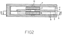
- a groove (2) of the adjustable wheel (6) and a groove (3) of the auxiliary wheel (7) are provided in a clamp frame (1), and are divided by a partition (4).
- the surfaces of the adjustable wheel (6) and the auxiliary wheel (7) are flat. (please refer to Fig. 6) if the surface is circular, clearance will be produced in the central part of the surface of the adjustable wheel ; therefore a flat surface is used to permit for adjustment.
- the method of adjusting the flow rate inside the pipe (5) of the clamp frame (1) makes use of the clearance between the inclined plane (9) of the bottom and the adjustable wheel (6) to decrease it, or increase it for effective flow rate adjustment.
- the adjustable wheel (6) and the auxiliary wheel (7) are connnected by an axle (11) which slides in the groove (12), a guided protuberance (8) is provided in groove (2) in the lower part of the adjustable wheel (6) in order to prevent the undulation of the adjustable wheel (6), the groove (3) at the lower part of the auxiliary wheel (7) is tightly engaged with the auxiliary wheel (7) and also has the function of preventing the undulation of the adjustable wheel (6).
- a space remains between the adjustable - wheel (6) and the groove (2) of the adjustable wheel (6) when the pipe (5) is forged into by tight clamping.
- the present invention can be exactly adjusted and can prevent shocking during transfusing liquid or blood ; therefore, it can be used for accurate transfusion. By reason of the large width of the wheels, it is convenient and accurate.
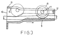
- Fig. 3 the sectional view taken from lines II-II of Fig. 2.
- the length of the inlet (10) of the wheel and the outside diameter of the adjustable wheel (6) are well-matched.
- Axle (11) is placed into the groove (12) of the clamp frame (1).
- a partition (4) where the wheel is.pressed forward to.
- the pipe (5) is inserted in the clamp frame (1).
- the return-preventing plate (13) which is opposite ot the arrow direction, and loosen the pipe (5) from the adjusting position of clamp frame (1) ; therefore, full flow rate is obtained.
- the wheel is rotated too violently, its indentation (15) in the surface of the wheel will be scraped and engaged by the knife edge (14) at the tip of return-preventing plate (13). If the wheel is lifted a little bit, pipe (5) is easier to be moved.
- the indentation (15) of the wheel can prevent the slipping of the wheel.
- the inclined surface (9) of the bottom is shaped into a conus. No matter how long the time has elapsed, the adjusting position remains unchanged.
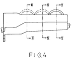
- Fig. 5 is composed of three sectional views in which the wheels are in different positions due to the rotary translation of the wheels while adjusting the flow rate. It is the above description that the inclined surface (9) of the bottom is shaped into a cone.
- the shape of the pipe (5) changes from roundness to ellipse by reason of the pressure of the adjustable wheel (6).
- the width of the adjustable wheel (6) is equal to the outside diameter of the pipe (5) and the pipe (5) is pressed, so that the rim of the pipe (5) is forced into the clearance and gradually inserted into the two inner-side space.
- the inside cross- sectional area is gradually decreased, so that the flow rate is naturally decreased.
- the flow rate inside the pipe (5) can be slighted adjusted and decreased exactly by pressing the wheel so as to let the part where the outside diameter of the pipe (5) is widened with force into the clearance. No matter how great the shocking is, the flow rate can be adjusted accurately, and the wheel will not be loosened due to the fact that the adjusting part is clamped in both sides, Also, the wheel being used for pressing can prevent the sinking of the portion around the adjusting part of the pipe (5).
Landscapes
- Health & Medical Sciences (AREA)
- Heart & Thoracic Surgery (AREA)
- Pulmonology (AREA)
- Engineering & Computer Science (AREA)
- Anesthesiology (AREA)
- Biomedical Technology (AREA)
- Hematology (AREA)
- Life Sciences & Earth Sciences (AREA)
- Animal Behavior & Ethology (AREA)
- General Health & Medical Sciences (AREA)
- Public Health (AREA)
- Veterinary Medicine (AREA)
- Infusion, Injection, And Reservoir Apparatuses (AREA)
Priority Applications (1)
| Application Number | Priority Date | Filing Date | Title |
|---|---|---|---|
| EP82108328A EP0103036A1 (de) | 1982-09-09 | 1982-09-09 | Regulier- und Absperrvorrichtung an Versorgungsschläuchen für Blut und Flüssigkeiten |
Applications Claiming Priority (1)
| Application Number | Priority Date | Filing Date | Title |
|---|---|---|---|
| EP82108328A EP0103036A1 (de) | 1982-09-09 | 1982-09-09 | Regulier- und Absperrvorrichtung an Versorgungsschläuchen für Blut und Flüssigkeiten |
Publications (1)
| Publication Number | Publication Date |
|---|---|
| EP0103036A1 true EP0103036A1 (de) | 1984-03-21 |
Family
ID=8189220
Family Applications (1)
| Application Number | Title | Priority Date | Filing Date |
|---|---|---|---|
| EP82108328A Ceased EP0103036A1 (de) | 1982-09-09 | 1982-09-09 | Regulier- und Absperrvorrichtung an Versorgungsschläuchen für Blut und Flüssigkeiten |
Country Status (1)
| Country | Link |
|---|---|
| EP (1) | EP0103036A1 (de) |
Cited By (1)
| Publication number | Priority date | Publication date | Assignee | Title |
|---|---|---|---|---|
| CN103948987A (zh) * | 2014-03-07 | 2014-07-30 | 烟台凯博机械自动化设备有限公司 | 输液器流速调节器的调节轮自动安装装置 |
Citations (3)
| Publication number | Priority date | Publication date | Assignee | Title |
|---|---|---|---|---|
| DE1934337A1 (de) * | 1968-10-16 | 1970-04-23 | Baxter Laboratories Inc | Rollklemmenvorrichtung |
| US3685787A (en) * | 1969-09-08 | 1972-08-22 | Marvin Adelberg | Apparatus for regulating fluid flow through plastic tubing |
| GB2020785A (en) * | 1978-05-12 | 1979-11-21 | Abbott Lab | Device for regulating flow through flexible tubing |
-
1982
- 1982-09-09 EP EP82108328A patent/EP0103036A1/de not_active Ceased
Patent Citations (3)
| Publication number | Priority date | Publication date | Assignee | Title |
|---|---|---|---|---|
| DE1934337A1 (de) * | 1968-10-16 | 1970-04-23 | Baxter Laboratories Inc | Rollklemmenvorrichtung |
| US3685787A (en) * | 1969-09-08 | 1972-08-22 | Marvin Adelberg | Apparatus for regulating fluid flow through plastic tubing |
| GB2020785A (en) * | 1978-05-12 | 1979-11-21 | Abbott Lab | Device for regulating flow through flexible tubing |
Cited By (2)
| Publication number | Priority date | Publication date | Assignee | Title |
|---|---|---|---|---|
| CN103948987A (zh) * | 2014-03-07 | 2014-07-30 | 烟台凯博机械自动化设备有限公司 | 输液器流速调节器的调节轮自动安装装置 |
| CN103948987B (zh) * | 2014-03-07 | 2015-11-11 | 烟台凯博机械自动化设备有限公司 | 输液器流速调节器的调节轮自动安装装置 |
Similar Documents
| Publication | Publication Date | Title |
|---|---|---|
| US4470586A (en) | Machine clamp rockable in T slot | |
| US4850757A (en) | Rotary cutting tool | |
| US4463644A (en) | Straight edge guide | |
| DE105017T1 (de) | Durchflussregler. | |
| EP0085156B1 (de) | Einmesser-Reibahle | |
| US4381103A (en) | Straight edge guide | |
| JPH0333365Y2 (de) | ||
| US5779249A (en) | Seat height adjusting means of a bicycle | |
| US6814526B2 (en) | Insert holder for parting and grooving operations | |
| DE1934337A1 (de) | Rollklemmenvorrichtung | |
| US2705441A (en) | Hold-down clamp | |
| DE2701534C3 (de) | Aufspannvorrichtung für Kraftfahrzeugräder | |
| US4463928A (en) | Clamp regulator for transfusing liquid and blood | |
| GB1563433A (en) | Device for adjustably locking a movable part relative to a fixed structure | |
| WO2015185396A1 (de) | Befestigungsvorrichtung zur befestigung eines gegenstandes an einer wand und befestigungssystem | |
| US4501519A (en) | Threading die couple | |
| CN113118490A (zh) | 一种三通阀体零部件的中头加工工装 | |
| US2820276A (en) | Split band clamp | |
| US2382571A (en) | Adjustable supporting tool | |
| EP0019840B1 (de) | Verstellbar anklemmbarer Motorradlenker | |
| JPS5842083Y2 (ja) | 手引きのこぎり | |
| DE2033876A1 (de) | Maschine zum Drehantrieb des Bodens ernes Uhrengehauses oder eines Messgeräts | |
| DE642577C (de) | Gewindebohrvorrichtung mit Abgratschneideisen | |
| DE2843778C3 (de) | Bohrwerkzeug | |
| JPS6118444Y2 (de) |
Legal Events
| Date | Code | Title | Description |
|---|---|---|---|
| PUAI | Public reference made under article 153(3) epc to a published international application that has entered the european phase |
Free format text: ORIGINAL CODE: 0009012 |
|
| AK | Designated contracting states |
Designated state(s): AT BE CH DE FR GB IT LI LU NL SE |
|
| 17P | Request for examination filed |
Effective date: 19840203 |
|
| STAA | Information on the status of an ep patent application or granted ep patent |
Free format text: STATUS: THE APPLICATION HAS BEEN REFUSED |
|
| 18R | Application refused |
Effective date: 19871011 |