EP0103063A2 - Chaudière de chauffage central en fonte de fer - Google Patents
Chaudière de chauffage central en fonte de fer Download PDFInfo
- Publication number
- EP0103063A2 EP0103063A2 EP83103951A EP83103951A EP0103063A2 EP 0103063 A2 EP0103063 A2 EP 0103063A2 EP 83103951 A EP83103951 A EP 83103951A EP 83103951 A EP83103951 A EP 83103951A EP 0103063 A2 EP0103063 A2 EP 0103063A2
- Authority
- EP
- European Patent Office
- Prior art keywords
- gas flue
- combustion chamber
- heating gas
- heating
- central heating
- Prior art date
- Legal status (The legal status is an assumption and is not a legal conclusion. Google has not performed a legal analysis and makes no representation as to the accuracy of the status listed.)
- Ceased
Links
- 238000010438 heat treatment Methods 0.000 title claims abstract description 56
- 229910001018 Cast iron Inorganic materials 0.000 title claims description 5
- 238000002485 combustion reaction Methods 0.000 claims abstract description 24
- 239000007789 gas Substances 0.000 claims description 52
- 238000001816 cooling Methods 0.000 claims description 4
- XLYOFNOQVPJJNP-UHFFFAOYSA-N water Substances O XLYOFNOQVPJJNP-UHFFFAOYSA-N 0.000 claims description 4
- 238000009826 distribution Methods 0.000 claims description 3
- 230000000149 penetrating effect Effects 0.000 claims description 3
- 239000002253 acid Substances 0.000 claims description 2
- 239000011248 coating agent Substances 0.000 claims description 2
- 238000000576 coating method Methods 0.000 claims description 2
- 238000009833 condensation Methods 0.000 description 3
- 230000005494 condensation Effects 0.000 description 3
- 238000004140 cleaning Methods 0.000 description 2
- 238000010276 construction Methods 0.000 description 2
- 238000005260 corrosion Methods 0.000 description 2
- 230000007797 corrosion Effects 0.000 description 2
- 230000017525 heat dissipation Effects 0.000 description 2
- 238000000926 separation method Methods 0.000 description 2
- 238000004804 winding Methods 0.000 description 2
- UGFAIRIUMAVXCW-UHFFFAOYSA-N Carbon monoxide Chemical compound [O+]#[C-] UGFAIRIUMAVXCW-UHFFFAOYSA-N 0.000 description 1
- 238000005266 casting Methods 0.000 description 1
- 238000001704 evaporation Methods 0.000 description 1
- 230000008020 evaporation Effects 0.000 description 1
- 230000029142 excretion Effects 0.000 description 1
- 239000003546 flue gas Substances 0.000 description 1
- 239000006260 foam Substances 0.000 description 1
- 238000009413 insulation Methods 0.000 description 1
- 239000000463 material Substances 0.000 description 1
- 238000009827 uniform distribution Methods 0.000 description 1
Images


Classifications
-
- F—MECHANICAL ENGINEERING; LIGHTING; HEATING; WEAPONS; BLASTING
- F24—HEATING; RANGES; VENTILATING
- F24H—FLUID HEATERS, e.g. WATER OR AIR HEATERS, HAVING HEAT-GENERATING MEANS, e.g. HEAT PUMPS, IN GENERAL
- F24H1/00—Water heaters, e.g. boilers, continuous-flow heaters or water-storage heaters
- F24H1/22—Water heaters other than continuous-flow or water-storage heaters, e.g. water heaters for central heating
- F24H1/24—Water heaters other than continuous-flow or water-storage heaters, e.g. water heaters for central heating with water mantle surrounding the combustion chamber or chambers
- F24H1/26—Water heaters other than continuous-flow or water-storage heaters, e.g. water heaters for central heating with water mantle surrounding the combustion chamber or chambers the water mantle forming an integral body
- F24H1/28—Water heaters other than continuous-flow or water-storage heaters, e.g. water heaters for central heating with water mantle surrounding the combustion chamber or chambers the water mantle forming an integral body including one or more furnace or fire tubes
Definitions
- the invention relates to a central heating boiler made of cast iron with a combustion chamber and a subsequent heating gas flue for cooling the heating gases to below the dew point.
- a boiler of this type also called a condensing boiler, allows the exhaust gases to be cooled to extremely low temperatures. As a result, the heat of condensation of the vaporous water contained in the exhaust gas can also be used.
- Boilers are known in which the boiler is followed by an exhaust gas heat exchanger for cooling the exhaust gases. Boilers are also known in which the necessary heat exchanger surface is integrated in the boiler body. The surface on the hot gas side must consist of corrosion-resistant material.
- a boiler of the known type with a cooling of the heating gases to below the dew point should be designed so that it has optimal properties for the intended purpose.
- this is achieved by a horizontal arrangement of the combustion chamber and the heating gas flue with a constant inclination from the burner end of the combustion chamber to the rear end of the heating gas flue.
- Such a boiler is ideally suited to allow the desired condensation to take place within the combustion chamber and the downstream train, particularly in the partial load range. Due to the slight inclination towards the end of the boiler, the resulting condensate can flow from where it has to be drained off through a drain connection.
- the boiler can be designed for a horizontal arrangement. In this case, the combustion chamber and the windings of the heating gas flue are next to each other, but with a slight downward slope towards the flue gas nozzle. If the boiler is to be arranged vertically, the combustion chamber and the windings of the heating gas flue can lie one below the other, whereby the slope must also be observed.
- the cast iron boiler allows the monoblock construction.
- the result is a closed boiler body in the form of a housing with a unit consisting of the combustion chamber and the heating gas flue penetrating it.
- a boiler of this type can be produced in the casting process without great difficulty. It is very economical and has sufficient corrosion protection. For safety reasons, the surfaces in contact with the heating gas can also be provided with a temperature and acid-resistant coating.
- heating gases can also enter the heating gas flue directly.
- a distribution channel below the constriction should be designed so that its cross-section tapers from sub-channel to sub-channel, whereby a uniform distribution of the heating gases is achieved on the sub-channels.
- the described design results in increased heat dissipation in conjunction with a lowering of the temperature of the heating gases.
- a baffle at the end of the hot gas flue in front of the mouth of the subchannels and an exhaust pipe arranged above it. In this way, no condensate is entrained in the exhaust gas flow. It separates from the impact surface, which is further promoted by an increased inclination of the subchannels in the mouth area. The exhaust gas then passes into the exhaust pipe above the condensate collection chamber.
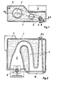
- the boiler consists of a single block in the form of a housing 1 with a combustion chamber 2 penetrating it, at the rear end of which a meandering heating gas duct 3 is connected.
- a meandering heating gas duct 3 is connected to the rear end of the heating gas duct 3, where the condensate can be removed through a drainage connection 4.
- the exhaust gases flow through an exhaust pipe 5 acting as an exhaust to the outside.
- the boiler is ideal for use with a modulating oil or gas fan burner 6, i.e. a burner, the output of which can be changed as required. It has a temperature-controlled, slidingly variable boiler temperature control.
- the deliberately chosen cast iron monoblock construction makes the boiler particularly suitable for this mode of operation. Since there are no joints, it is absolutely leak-proof on the hot gas side. It can therefore be surrounded by full foam insulation 7.
- connection to the heating network is made via the flow connector 8 and the return connector 9. Cleaning the heating gas flue 3 is possible after removing a cleaning cover 10. As a result of the inclination of the heating gas flue 3, combined with a taper towards the exhaust pipe 5, a space 11 is created for a switch box.
- the flames are reversed in the combustion chamber 2.
- the flames and heating gases first flow back to the burner 6, the head of which they heat, in order to get into the heating gas flue 3 through a flow opening 12.
- a constriction 13 is formed by two laterally projecting water pockets 14. Through this constriction 13, part of the heating gases and any condensate that may arise in the combustion chamber 2 can flow directly into the heating gas duct 3.
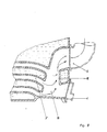
- the heating gas flue 3 initially has a distribution channel 3 t which merges into a number of subchannels 3 ′′ and tapers from subchannel to subchannel. This ensures that the heating gases are evenly distributed over the subchannels.
- the subchannels 3 '' end at the end in a condensate collection chamber 15.
- a somewhat stronger inclination in the mouth area and a baffle surface 16 increase the condensate excretion.
- the exhaust pipe 5 is arranged above the mouths of the subchannels 3 ′′. This prevents condensate from being entrained by the exhaust gas flow.
Landscapes
- Engineering & Computer Science (AREA)
- Physics & Mathematics (AREA)
- Thermal Sciences (AREA)
- Chemical & Material Sciences (AREA)
- Combustion & Propulsion (AREA)
- Mechanical Engineering (AREA)
- General Engineering & Computer Science (AREA)
- Gas Burners (AREA)
- Incineration Of Waste (AREA)
Applications Claiming Priority (6)
| Application Number | Priority Date | Filing Date | Title |
|---|---|---|---|
| DE8222718U | 1982-08-12 | ||
| DE19828222718 DE8222718U1 (de) | 1982-08-12 | 1982-08-12 | Zentralheizungskessel aus gusseisen |
| DE3234293 | 1982-09-16 | ||
| DE19823234293 DE3234293C2 (de) | 1982-08-12 | 1982-09-16 | Zentralheizungskessel aus Gußeisen |
| DE19823245575 DE3245575A1 (de) | 1982-12-09 | 1982-12-09 | Zentralheizungskessel |
| DE3245575 | 1982-12-09 |
Publications (2)
| Publication Number | Publication Date |
|---|---|
| EP0103063A2 true EP0103063A2 (fr) | 1984-03-21 |
| EP0103063A3 EP0103063A3 (fr) | 1984-09-12 |
Family
ID=27190383
Family Applications (1)
| Application Number | Title | Priority Date | Filing Date |
|---|---|---|---|
| EP83103951A Ceased EP0103063A3 (fr) | 1982-08-12 | 1983-04-22 | Chaudière de chauffage central en fonte de fer |
Country Status (1)
| Country | Link |
|---|---|
| EP (1) | EP0103063A3 (fr) |
Cited By (1)
| Publication number | Priority date | Publication date | Assignee | Title |
|---|---|---|---|---|
| DE3432526A1 (de) * | 1984-09-05 | 1986-03-13 | Thyssen Industrie Ag, 4300 Essen | Heizkessel, insbesondere gasheizkessel |
Family Cites Families (5)
| Publication number | Priority date | Publication date | Assignee | Title |
|---|---|---|---|---|
| CH433654A (de) * | 1965-06-09 | 1967-04-15 | Oil Therm Ag | Olbefeuerter Heizkessel mit gleich langem Strömungsweg für das gesamte Rauchgasvolumen |
| AT284156B (de) * | 1968-08-30 | 1970-09-10 | Waagner Biro Ag | Flammrohr-Rauchrohrkessel |
| FR2198610A5 (fr) * | 1972-08-31 | 1974-03-29 | Mimric Guy | |
| DE2507595A1 (de) * | 1975-02-21 | 1976-09-02 | Vama Vertrieb | Heizkessel |
| DE3100888A1 (de) * | 1981-01-14 | 1982-09-02 | Hoval Interliz AG, 9490 Vaduz-Neugut | Heizkessel fuer niedertemperatur-heizungen |
-
1983
- 1983-04-22 EP EP83103951A patent/EP0103063A3/fr not_active Ceased
Cited By (1)
| Publication number | Priority date | Publication date | Assignee | Title |
|---|---|---|---|---|
| DE3432526A1 (de) * | 1984-09-05 | 1986-03-13 | Thyssen Industrie Ag, 4300 Essen | Heizkessel, insbesondere gasheizkessel |
Also Published As
| Publication number | Publication date |
|---|---|
| EP0103063A3 (fr) | 1984-09-12 |
Similar Documents
| Publication | Publication Date | Title |
|---|---|---|
| DE2837004A1 (de) | Verfahren und heizungskessel zum erwaermen des heizwassers in einer warmwasser-zentralheizungsanlage, insbesondere fuer ein- und mehrfamilienwohnhaeuser | |
| DE2445841A1 (de) | Waermeerzeuger mit kondensierung der verbrennungsprodukte und heizverfahren fuer eine waermeuebertragende fluessigkeit | |
| CH616499A5 (en) | Central heating system with a boiler and an additional heat exchanger for preheating the medium flowing back to the boiler | |
| DE2950901A1 (de) | Zentralheizungsanlage | |
| DE3329777A1 (de) | Heizungskessel fuer fluessige und gasfoermige brennstoffe | |
| EP0123994A1 (fr) | Chaudière à condensation avec un élément échangeur de chaleur en zig-zag | |
| DE3347559A1 (de) | Niedertemperaturheizungskessel, insbesondere fuer mittlere und grosse leistungsbereiche | |
| DE4223799A1 (de) | Gasheizgerät | |
| DE8222718U1 (de) | Zentralheizungskessel aus gusseisen | |
| DE3234293C2 (de) | Zentralheizungskessel aus Gußeisen | |
| DE3245575A1 (de) | Zentralheizungskessel | |
| CH678655A5 (fr) | ||
| DE3015377A1 (de) | Heizungskessel fuer warmwasserheizungsanlagen | |
| EP0031571B1 (fr) | Chaudière de chauffage | |
| DE3108452C2 (de) | Öl/Gas-Heizkessel | |
| DE2758181A1 (de) | Vorrichtung zur rueckgewinnung der abgaswaerme von heizungsfeuerungen | |
| DE434092C (de) | Steilrohrkessel | |
| DE10055053C1 (de) | Wärmetauscher | |
| EP0060338A2 (fr) | Chaudière à combustible | |
| DE4116383A1 (de) | Gliederheizkessel | |
| DE4111232C2 (fr) | ||
| DE19941812C1 (de) | Gußeiserner Heizkessel | |
| AT382953B (de) | Heizkessel mit einem brennraum | |
| AT139541B (de) | Ofen, Kochherd od. dgl. für Dauerbrand. | |
| DE573468C (de) | Vorrichtung zur Verwertung der Abgase von Heizkesseln, OEfen, Herden |
Legal Events
| Date | Code | Title | Description |
|---|---|---|---|
| PUAI | Public reference made under article 153(3) epc to a published international application that has entered the european phase |
Free format text: ORIGINAL CODE: 0009012 |
|
| AK | Designated contracting states |
Designated state(s): AT BE CH DE FR GB IT LI NL |
|
| PUAL | Search report despatched |
Free format text: ORIGINAL CODE: 0009013 |
|
| AK | Designated contracting states |
Designated state(s): AT BE CH DE FR GB IT LI NL |
|
| 17P | Request for examination filed |
Effective date: 19841008 |
|
| STAA | Information on the status of an ep patent application or granted ep patent |
Free format text: STATUS: THE APPLICATION HAS BEEN REFUSED |
|
| 18R | Application refused |
Effective date: 19861215 |
|
| RIN1 | Information on inventor provided before grant (corrected) |
Inventor name: KOLBE, GERHOLD Inventor name: KLOSE, EGON Inventor name: STEPHAN, ERNST WILHELM, DIPL.-ING. |