EP0103072A1 - Stangenzuführvorrichtung für einen Drehautomaten - Google Patents
Stangenzuführvorrichtung für einen Drehautomaten Download PDFInfo
- Publication number
- EP0103072A1 EP0103072A1 EP83105553A EP83105553A EP0103072A1 EP 0103072 A1 EP0103072 A1 EP 0103072A1 EP 83105553 A EP83105553 A EP 83105553A EP 83105553 A EP83105553 A EP 83105553A EP 0103072 A1 EP0103072 A1 EP 0103072A1
- Authority
- EP
- European Patent Office
- Prior art keywords
- guide
- oil
- guide tube
- channel
- feed
- Prior art date
- Legal status (The legal status is an assumption and is not a legal conclusion. Google has not performed a legal analysis and makes no representation as to the accuracy of the status listed.)
- Granted
Links
- 239000000463 material Substances 0.000 claims abstract description 52
- 230000008878 coupling Effects 0.000 claims abstract description 5
- 238000010168 coupling process Methods 0.000 claims abstract description 5
- 238000005859 coupling reaction Methods 0.000 claims abstract description 5
- 229920003023 plastic Polymers 0.000 claims description 12
- 239000004033 plastic Substances 0.000 claims description 12
- 229920002635 polyurethane Polymers 0.000 claims description 6
- 239000004814 polyurethane Substances 0.000 claims description 6
- 239000011810 insulating material Substances 0.000 claims description 5
- 239000004576 sand Substances 0.000 claims description 3
- 238000001125 extrusion Methods 0.000 claims 3
- 238000011161 development Methods 0.000 description 3
- 238000010276 construction Methods 0.000 description 2
- 238000013461 design Methods 0.000 description 2
- 230000000284 resting effect Effects 0.000 description 2
- 238000013016 damping Methods 0.000 description 1
- 238000009413 insulation Methods 0.000 description 1
- 238000012423 maintenance Methods 0.000 description 1
- 239000002184 metal Substances 0.000 description 1
- 238000000034 method Methods 0.000 description 1
- 238000000465 moulding Methods 0.000 description 1
- 238000012545 processing Methods 0.000 description 1
- 239000007787 solid Substances 0.000 description 1
Images



Classifications
-
- B—PERFORMING OPERATIONS; TRANSPORTING
- B23—MACHINE TOOLS; METAL-WORKING NOT OTHERWISE PROVIDED FOR
- B23B—TURNING; BORING
- B23B13/00—Arrangements for automatically conveying or chucking or guiding stock
-
- Y—GENERAL TAGGING OF NEW TECHNOLOGICAL DEVELOPMENTS; GENERAL TAGGING OF CROSS-SECTIONAL TECHNOLOGIES SPANNING OVER SEVERAL SECTIONS OF THE IPC; TECHNICAL SUBJECTS COVERED BY FORMER USPC CROSS-REFERENCE ART COLLECTIONS [XRACs] AND DIGESTS
- Y10—TECHNICAL SUBJECTS COVERED BY FORMER USPC
- Y10T—TECHNICAL SUBJECTS COVERED BY FORMER US CLASSIFICATION
- Y10T82/00—Turning
- Y10T82/25—Lathe
- Y10T82/2514—Lathe with work feeder or remover
- Y10T82/2516—Magazine type
- Y10T82/2518—Bar feeder
Definitions
- the invention relates to a rod feed device with an oil-containing guide tube mounted in a carrier and an axially movable in the guide tube, coupled to a feed drive, the front end of which carries a rotatable coupling element, and with an oil supply line and an oil return line.
- German laid-open specification 29 19 780 it is known to use a device for the loading of automatic lathes that process bar material, which device has a guide tube located behind the spindle of the lathe and in alignment therewith.
- a material bar to be machined by the lathe is accommodated in the guide tube and is advanced in a controlled manner by a slide movable in the longitudinal direction of the guide tube.
- a slide movable in the longitudinal direction of the guide tube In order to reduce the noise of material rods rotating rapidly in the guide tube, a certain amount of oil is ensured in the tube, the excess oil being able to escape on the non-hermetically sealed front side of the guide tube.
- the guide tube is filled with oil through a play between the slide designed as a piston and the guide tube.
- This device has the disadvantage that for loading the guide tube with a new material rod requires considerable space. After the slide has been moved backwards, the guide tube must either be pivoted away to the side or retracted so far that a new material rod can be inserted into the front end of the guide tube. Attempts have been made to simplify this cumbersome loading of the guide tube with a material bar by providing a drum-shaped magazine instead of the guide tube, on the circumference of which a plurality of guide tubes loaded with material bars are arranged.
- this measure is not only disadvantageous in that the number of stockable material bars is limited by the size of the drum, but also a corresponding number of guide tubes must be provided, only one of which is in the working position.
- the invention is intended to provide a bar feed device with a small footprint and a significantly simplified loading of the guide tube, each with a new material bar, in which the stocking of the material bars is not limited to a predetermined number of existing guide tubes.
- the invention provides a rod feed device with an oil-containing guide tube mounted on a carrier and an axially movable in the guide tube, coupled with a feed drive feed rod, the front end of which carries a rotatable coupling element, and with an oil feed line and an oil return line, the guide tube being on a guide channel formed in the carrier and coupled to at least one oil supply line and a cover which can be swiveled upward and which extends over the length of the guide channel, oil being supplied through the oil supply line in the closed guide tube of the guide channel during the advance of the material rod.
- the guide channel can be continuously flooded with 01 during the advance of the material bars, which means that the rotating material bar, regardless of its diameter and profile, centers itself in the guide channel. Since oil is always present in this way between the material rod and the inner wall of the guide channel, their wear and noise are significantly reduced.
- an oil collecting pan connected to the oil return line can be provided under the guide tube in a further development of the invention.
- a rod storage platform is provided on the side of the stand, the opening into the guide channel being blocked when the lid is closed. If the storage platform is formed from an inlet ramp provided on the carrier and the lower part of the cover, a material bar on the blocked storage platform automatically runs into the guide channel when the cover is opened.
- the carrier consists of an elongated profiled part, to which an existing example of polyurethane plastic strand is placed, in which the guide groove is formed.
- the plastic strand reduces the noise generated when the rotating material bar is fed.
- the cover consists of a frame profile, under which a further plastic strand, possibly made of polyurethane, is fastened, in the underside of which a guide channel is formed.
- the profile part can then be shaped in such a way that it encloses an oil supply channel and an oil discharge channel below the plastic strand, the oil supply channel being coupled to the guide trough via a plurality of branch channels.
- the profile part can also be equipped with at least one elongated, closed chamber which can be filled with insulating material, for example sand.
- the carrier can consist of three laterally interconnected extruded profiles, of which the outer extruded profile encloses a chamber filled with insulating material, the middle extruded profile has the oil supply duct and oil outflow duct on which the plastic strand is placed, and the third extruded profile, the backdrop for the guide body of the feed rod carries.
- At least one lever articulated on the machine frame can then be attached to the cover, with the arm of which a pivot drive, for example in the form of a piston-cylinder unit attached to the machine frame, is coupled.
- the bar feed device is mounted behind an automatic lathe and has a length perpendicular to the cross-sectional views shown in the figures of several meters, each corresponding to a material bar to be fed to the automatic lathe.
- a bar charger 30 for example in the construction known from DE-OS 23 50 105, is set up, of which only the upper part is indicated in FIG. 1.
- the bar feeder and the top of the bar loader are covered with a hood 50.
- the bar feed device has a support 25 mounted on a stand 52 shown in broken lines, in the surface of which a guide channel 4 for a material bar 6, which is approximately semicircular in cross section, is embedded.
- a guide channel 4 for a material bar 6, which is approximately semicircular in cross section is embedded.
- the oil supply line 12 is connected to an oil reservoir (not shown) and an oil feed pump.
- An outlet opening 14 of the oil collecting trough 13, which supports the carrier 25, is coupled to an oil return line 16 leading back into the oil reservoir.
- a plurality of lugs 23, which are spaced in the longitudinal direction, are fastened via a connecting piece 26, in the aligned through-bores of which a pivotable shaft 3 is rotatably mounted.
- a swivel arm 27 engages in a rotationally fixed manner, the free end 28 below the shaft 3 is coupled to a swivel motor designated as a whole by 29, which according to FIG. 2 can be a piston-cylinder unit fastened in the stand 52 below the carrier 25.
- the shaft 3 is connected in a rotationally fixed manner to a plurality of brackets 2, which are spaced apart in the longitudinal direction of the rod feed device, each of which extends in an arc over the carrier 25 to the operating side and above the guide trough 4 and at the end of a section 22 which extends downward onto the guide trough 4 is connected to a cover 21 which is continuous in the longitudinal direction of the bar feed device.
- the underside of the cover 21 facing the carrier 25 consists of three sections.
- the front section 31 facing the operating side is provided for flat support on a loading platform 5, which is provided with an inclined inlet ramp 51 and is yet to be explained, and has an inclined surface which extends upwards to the front.
- the middle section of the cover 21 is grooved on its underside in the form of an elongated channel 1, which in the exemplary embodiment shown has an approximately semicircular cross section and is aligned with the guide trough 4 when the bracket 2 is lowered.
- Channel 1 and guide trough 4 together form a guide tube, in which the back of the feed rod 7 detected material rod 6 is advanced in the automatic lathe, not shown.
- the rear section 32 of the cover 21 extends parallel to the surface of the carrier 25, but keeps a distance from the latter when the cover is closed in such a way that a longitudinal slot 33 remains, which will be discussed below.
- From the back of the cover 21 extends to the connecting piece 26, an intermediate piece 34 connected thereto, the intermediate piece 34, the connecting piece 26 and the upper side of the carrier 25 enclose a guide link 35, in which a guide block 10 fixedly connected to a chain 11 parallel to the guide tube is mobile. 2, a flag 8 extends from the guide block 10 through the longitudinal slot 33, which is connected to the feed rod 7.
- the guide block 10 therefore takes the feed rod 7 connected to it via the flag 8 when it moves within the guide link 35.
- the endless chain 11 runs around a sprocket arranged at the front end of the guide link 35 and another sprocket arranged at the rear end of the guide link 35, wherein the upper run 19 of the chain 11 according to FIG. 2 can be encapsulated above the intermediate piece 34.
- a drive motor not shown, is coupled to one of the sprockets around which the chain 11 rotates and is controlled in a manner known per se for advancing and retracting the feed rod 7.
- the bar loading device 30 has a plurality of posts 41 spaced apart in the longitudinal direction of the bar feeding device, each of which is equipped with a centrally driven, schematically illustrated chain elevator 42.
- a plurality of spaced lifters 43 are fastened to the chain elevator 42, each of which projects over the post 41 onto the bar feed device with a nose 45, the front, upper end of which can be provided with a throat 46.
- a plurality of spaced inlet flaps 47 are articulated on the post 41 between the lifters 43 so that they rest on the loading platform 5 in the rest position, the surface 48 of each inlet flap 47 continuing the slope 51 outward in the direction of the vertical upward movement of the lugs 45 of the lifters 43 crosses.
- the inlet flaps 47 are pivoted into the position 49 shown in dashed lines in order to open up the path of a material rod 6 resting in the throat 46.
- the nose 45 of the lifter 43 has passed the inlet flap 47 upwards, it falls onto the front end of the inlet platform 5, as shown in FIG. 1 in solid lines.
- the lifter 43 moves down, one in the The throat 46, the material rod at rest, is caught by the surfaces 48 of the inlet flap 47 and rolls on it via the inlet ramp 51 as far as against the front section 31 of the cover 21.
- the oil pump Before lifting the cover 21, the oil pump is switched over in such a way that the oil contained in the guide tube can drain through the oil drain line 16 to such an extent that no oil can escape laterally from the guide trough 4 when the cover 21 is open.
- the cover 21 After actuating the piston-cylinder unit 29, the cover 21 is pivoted upward to open the guide tube, so that the material rod 6 shown in the figures can roll into the guide channel 4.
- the end of the material rod 6 facing away from the automatic lathe is gripped in a manner known per se by a gripper and connected in a rotationally fixed manner to the rotatable coupling part of the feed rod 7.
- FIGS. 3 and 4 The embodiment of the bar feed device according to the invention shown in FIGS. 3 and 4 is fastened on a table top 61 which is mounted on solid stands 62, 63.
- the table top 61 can be adjusted in height relative to the foot 64 by means of several spindles 65.
- the carrier consists of three extruded profiles 70, 71, 72, which are arranged side by side and screwed.
- the extruded profiles 70, 71, 72 extend at least over the entire length of a material bar to be processed.
- the outer, front extruded profile 70 encloses a chamber 73 which can be filled with insulating material, for example sand.
- the extruded profile 70 is screwed to the top of the table 61.
- an elongated body 75 with a trapezoidal cross-section is set back somewhat as a feed screwed on the stage, the top of which has a backward and downward inclined, plane entry ramp 74 for a material bar, not shown.
- the middle extruded profile 71 is screwed onto the back of the front extruded profile 70 and has an U-shaped, upwardly open channel 76 with lugs 77, 78 directed inwards at the upper end in an upper section.
- Two channels 79, 80, closed in cross section, are formed beneath the channel 76, of which the front channel 79 serves as an oil return channel and the rear channel 80 serves as an oil supply channel.
- Oil return channel 79 and oil supply channel 80 are connected in a manner not shown via oil lines to an oil reservoir and an oil pump.
- In the U-channel 76 are inserted several plastic mold blocks of the same design, placed in the longitudinal direction, which consist of polyurethane and of which a mold block 82 is shown in section in FIG. 3.
- the mold block 82 is held in the U-channel 76 by the lugs 77, 78. It has at the front a back 83 which extends above the front nose 77 and which ends at the top with a flat, rearward-facing inlet surface 84 which is set down against the inlet ramp 74 and directed towards the center line of the feed pipe. On the rear side, the mold block 82 closes with the top of the rear nose 78. Between the back 83 and the rear part of the molding block 82 is formed a groove 85 with a circular arc shape in cross section. from the oil supply channel 80, a plurality of branch channels 86, spaced along the length of the device, lead through the mold blocks 82 into the groove 85.
- rear extruded profile 72 surrounds a channel 88, into each of which a shaft 90 with a splined sprocket 91 protrudes at the end facing the automatic lathe and at the rear end.
- the chain 4um (not shown in detail) runs around the two sprockets 91, the lower run of the chain extending freely through the channel 88 in this exemplary embodiment of the invention.
- a guide body 92 is connected to the upper run of the chain and is displaceable parallel to the guide tube in a link 93 of an attachment 94 screwed onto the upper side of the rear extruded profile 72.
- a lengthwise slot 95 extends in the longitudinal direction through the part of the attachment 94 resting on the rear side of the central extruded profile 71 for the flag connected to the guide body 92 on the one hand and the feed rod on the other hand.
- One of the shafts 90 is driven by an electric motor 96 flanged to the rear of the rear extruded profile 72.
- the cover 100 consists of a further extruded profile 102, on the underside of which a channel 104 which is open at the bottom and is U-shaped in cross section is formed.
- An inwardly directed, rear lug 106 and an inwardly directed front lug 108 anchor in the channel 104 a plurality of elongated, made of polyurethane and longitudinally juxtaposed plastic profile blocks, of which the profile block 110 is shown in section in FIG. 3.
- a channel 112 with a semicircular cross-section is incorporated into each profile block 110 from the underside in alignment with the groove 85, and closes backwards and downwards with the rear nose 106 and merges forwardly into an inclined surface 114.
- the front inclined surfaces 114 of the profile blocks 110 lie with the underside of the front nose 108 flat on the inlet surface 84 of the mold blocks 82.
- Fig. 4 shows schematically the design of the lid 100, parts of the device which are not required for understanding the lid movement being omitted.
- the lid 100 is secured to a shaft 122 via a plurality of longitudinally spaced, rearwardly projecting arms 120, with a lever 124 attached to at least one of the rear arms 120, which extends with respect to the shaft 122 to the side facing away from the lid 100 .
- a pin 126 is inserted into a bore of the lever 124, to which the fork-shaped end 128 of a piston 130 is articulated.
- the piston 130 belongs to a drive motor that has an oil or compressed air cylinder 132.
- the shaft 122 is mounted on the upper end of a plurality of spaced posts 134 which are connected to the table 61 or the stands 63.
- the cylinder 132 is hinged at 136 to a side flange 138.
- the cover 100 can be opened from the position shown in solid lines, closing the guide tube, to the position indicated by the dashed lines, by the piston 130 moving into the cylinder 132, the cylinder 132 makes a slight pivoting movement about its bearing 136.
- the operation of the device according to FIGS. 3 and 4 is the same as that of the exemplary embodiment shown and explained with reference to FIGS. 1 and 2 Invention.
- the particular advantage of this embodiment is the overall lightweight construction, since the extruded profiles 70, 71, 72, 102 can be made from extruded light metal profiles. Furthermore, the extruded profiles 70, 71, 72, 102 are easy to assemble, which considerably simplifies their replacement in the event of damage or maintenance work.
- the plastic mold blocks 82 and profile blocks 110 since a noise-damping material, for example polyurethane, can be selected for them.
- the cover closes the inlet from the loading platform 75 in an oil-tight manner during operation, since the inlet surface 84 is offset against the inlet ramp 74, the front edge of the molded part 102 abutting against the end of the outlet ramp 74, as shown in FIG. 3.
Landscapes
- Engineering & Computer Science (AREA)
- Mechanical Engineering (AREA)
- Turning (AREA)
Abstract
Description
- Die Erfindung betrifft eine Stangenzuführvorrichtung mit einem Öl enthaltenden, in einem Träger gelagerten Führungsrohr und einem in dem Führungsrohr axial beweglichen, mit einem Vorschubantrieb gekoppelten Schieber, dessen vorderes Ende ein drehbares Kupplungselement trägt, sowie mit einer Ölzuflußleitung und einer Ölrückflußleitung.
- Aus der deutschen Offenlegungsschrift 29 19 780 ist es bekannt, für die Beschickung von Stangenmaterial bearbeitenden automatischen Drehbänken eine Vorrichtung zu verwenden, welche ein hinter der Spindel der Drehbank gelegenes und mit dieser fluchtendes Führungsrohr aufweist. In dem Führungsrohr ist jeweils eine von der Drehbank zu bearbeitende Materialstange beherbergt und wird von einem in Längsrichtung des Führungsrohres beweglichen Schieber gesteuert vorgeschoben. Um den Lärm von im Führungsrohr rasch drehenden Materialstangen zu verringern, wird für die Anwesenheit einer gewissen Menge Öl im Rohr gesorgt, wobei das überschüssige Öl an der nicht hermetisch verschlossenen Vorderseite des Führungsrohres austreten kann. Die Beschickung des Führungsrohres mit Öl geschieht durch ein Spiel zwischen dem als Kolben ausgebildeten Schieber und dem Führungsrohr.
- Diese Vorrichtung hat den Nachteil, daß zur Beschickung des Führungsrohres jeweils mit einer neuen Materialstange ein erheblicher Raumbedarf erforderlich ist. Das Führungsrohr muß nach dem Rückwärtsfahren des Schiebers entweder zur Seite weggeschwenkt oder soweit zurückgefahren werden, daß eine neue Materialstange in das vordere Ende des Führungsrohres eingeführt werden kann. Man hat versucht, dieses umständliche Beschicken des Führungsrohres mit einer Materialstange dadurch zu vereinfachen, daß anstelle des Führungsrohres ein trommelförmiges Magazin vorgesehen wird, an dessen Umfang mehrere mit Materialstangen beschickte Führungsrohre angeordnet sind. Diese Maßnahme ist jedoch nicht nur darin nachteilig, daß die Anzahl der bevorratbaren Materialstangen durch die Dimension der Trommel begrenzt ist, sondern es muß auch eine entsprechende Anzahl von Führungsrohren bereitgestellt werden, von denen nur jeweils eines sich in Arbeitsstellung befindet.
- Im übrigen ist für die Durchflutung des bekannten Führungsrohres mit geräuschdämmendem Öl eine Anpassung der lichten Weite des Führungsrohres an den größten Durchmesser der zu verarbeitenden Materialstange erforderlich. Dies hat zur Folge, daß zur Zuführung von Materialstangen unterschiedlicher Durchmesser auch Führungsrohre entsprechend unterschiedlicher lichter Weiten erforderlich sind.
- Aus der DE-OS 23 50 105 ist es zwar bekannt, das Führungsrohr längs zu teilen, wobei der obere Teil des Führungsrohres zur seitlichen Beschickung mit einer Materialstange angehoben werden kann. Bei dieser Vorrichtung tritt trotz schalldämmender Maßnahmen durch die in dem geschlossenen Führungsrohr rotierende und auf den Drehautomaten vorgeschobenen Materialstange noch immer ein erheblicher Geräuschpegel auf und bei unrundem Querschnitt verschleißt die Innenkontur des Führungsrohres.
- Mit der Erfindung soll eine Stangenzuführvorrichtung mit geringem Platzbedarf und wesentlich vereinfachter Beschickung des Führungsrohres mit jeweils einer neuen Materialstange geschaffen werden, bei der die Bevorratung der Materialstangen nicht auf eine vorgegebene Anzahl vorhandener Führungsrohre begrenzt ist.
- Die Erfindung sieht dazu eine Stangenzuführvorrichtung mit einem Öl enthaltenden, auf einem Träger gelagerten Führungsrohr und einer in dem Führungsrohr axial beweglichen, mit einem Vorschubantrieb gekoppelten Vorschubstange, deren vorderes Ende ein drehbares Kupplungselement trägt, sowie mit einer Ölzuflußleitung und einer Ölrückflußleitung, wobei das Führungsrohr auf einer in dem Träger ausgebildeten und mit wenigstens einer Ölzuflußleitung gekoppelten Führungsrinne und einem nach oben abschwenkbaren, sich über die Länge der Führungsrinne erstreckenden Deckel besteht, wobei während des Vorschubs der Materialstange im geschlossenen Führungsrohr der Führungsrinne durch die Ölzuflußleitung Öl zugeführt ist.
- Der Führungskanal kann dadurch während des Vorschubs der Materialstangen ständig von 01 durchflutet werden, wodurch sich die rotierende Materialstange, unabhängig von ihrem Durchmesser und Profil, im Führungskanal selbst zentriert. Da auf diese Weise zwischen der Materialstange und der Innenwand des Führungskanals stets Öl vorhanden ist, werden deren Abnutzung und die Geräuschentwicklung wesentlich gemindert. Zur sauberen Ableitung des aus dem Führungsrohr austretenden Öls kann in Weiterbildung der Erfindung eine mit der Ölrückflußleitung verbundene Ölauffangwanne unter dem Führungsrohr vorgesehen sein.
- Die Beschickung des Führungsrohrs etwa aus einem der erwähnten Geräte wird erleichtert, wenn in Weiterbildung der Erfindung seitlich am Ständer eine Stangen-Bevorratungsbühne vorgesehen ist, deren Einmündung in den Führungskanal bei geschlossenem Deckel blockiert ist. Wenn die Bevorratungsbühne aus einer am Träger vorgesehenen Einlauframpe und dem unteren Teil des Deckels gebildet ist, läuft eine auf der blockierten Bevorratungsbühne bevorraTETE Materialstange beim Öffnen des Deckels automatisch in den Führungskanal ein.
- In*zweckmäßiger Weiterbildung der Erfindung besteht der Träger aus einem langgestreckten Profilteil, auf das ein beispielsweise aus Polyurethan bestehender Kunststoffstrang aufgesetzt ist, in welchem die Führungsrinne ausgebildet ist. Durch den Kunststoffstrang wird die Geräuschentwicklung beim Vorschub der rotierenden Materialstange herabgesetzt. Eine weitere Minderung der Geräuschentwicklung wird erreicht, wenn der Deckel aus einem Rahmenprofil besteht, unter welchem ein weiterer, ggfs. aus Polyurethan bestehender Kunststoffstrang befestigt ist, in dessen Unterseite ein Führungskanal ausgebildet ist.
- Das Profilteil kann dann so geformt sein, daß es unterhalb des Kunststoffstranges einen Ölzufuhrkanal und einen Ölableitkanal umschließt, wobei der Ölzufuhrkanal über mehrere Stichkanäle mit der Führungsrinne gekoppelt ist.
- *besonders Zur Geräuschdämmung kann das Profilteil ferner mit wenigstens einer langgestreckten, geschlossenen Kammer ausgerüstet sein, welche mit Dämmstoff, beispielsweise Sand, gefüllt werden kann.
- Zur besonders einfachen Montage der Vorrichtung kann der Träger aus drei seitlich miteinander verbundenen Strangprofilen bestehen, von denen das äußere Strangprofil eine mit Dämmstoff gefüllte Kammer umschließt, das mittlere Strangprofil den Ölzufuhrkanal und Ölabflußkanal aufweist, auf das der Kunststoffstrang aufgesetzt ist, und das dritte Strangprofil, die Kulisse für den Führungskörper der Vorschubstange trägt. An dem Deckel kann dann wenigstens ein am Maschinengestell angelenkter Hebel befestigt sein, mit dessen Arm ein Schwenkantrieb, etwa in der form einer am Maschinengestell befestigten Kolbenzylindereinheit, gekoppelt ist.
- Die Erfindung wird nachstehend anhand der in der beigefügten Zeichnung dargestellten Ausführungsbeispiele im einzelnen beschrieben. Es zeigen:
- Fig. 1 die Ansicht eines schematischen Querschnitts durch den oberen Teil einer Stangenzuführvorrichtung;
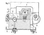
- Fig. 2 die Ansicht eines schematischen Querschnitts wesentlicher Teile aus Fig. l;
- Fig. 3 die Ansicht eines Querschnitts einer zweiten Ausführungsform der Erfindung; und
- Fig. 4 eine schematische Darstellung zur Erläuterung der Abschwenkbewegung des Deckels.
- Auf einem nicht dargestellten Ständer ist die Stangenzuführvorrichtung hinter einem Drehautomaten montiert und hat eine Länge senkrecht zu den in den Figuren dargestellten Querschnittsansichten von mehreren Metern entsprechend jeweils einer dem Drehautomaten zuzuführenden Materialstange. Vor der Stangenzuführvorrichtung ist auf der Bedienungsseite, die in den Figuren der linken Seite entspricht, ein Stangenladegerät 30, beispielsweise in der aus der DE-OS 23 50 105 bekannten Bauweise, aufgestellt, von der in Fig. 1 nur der obere Teil angedeutet ist. Die Stangenzuführvorrichtung und der obere Teil des Stangenladegeräts ist mit einer Haube 50 abgedeckt.
- Im einzelnen weist die Stangenzuführvorrichtung gemäß der ersten Ausführungsform der Erfindung einen auf einem gestrichelt dargestellten Ständer 52 montierten Träger 25 auf, in dessen Oberfläche eine im Querschnitt etwa halbkreisförmige Führungsrinne 4 für eine Materialstange 6 eingelassen ist. Wie Fig. 2 zeigt, mündet in die Führungsrinne 4 wenigstens ein sich von unten durch den Träger 25 erstreckender Ölzufuhrkanal 24, der sich nach unten in einer Ölzufuhrleitung 12 fortsetzt. Die Ölzufuhrleitung 12 ist mit einem nicht dargestellten Ölvorratsbehälter und einer Ölförderpumpe verbunden. Eine Ablauföffnung 14 der den Träger 25 unterfassenden Ölauffangwann 13 ist mit einer in den Ölvorratsbehälter zurückführenden Ölrückflußleitung 16 gekoppelt. An der relativ zur Bedienungsseite rückwärtigen Seite des Trägers 25 sind über ein Verbindungsstück 26 mehrere in Längsrichtung beabstandete Nasen 23 befestigt, in deren fluchtenden Durchbohrungen eine schwenkbare Welle 3 drehbar gelagert ist. An der Welle 3 greift drehfest ein Schwenkarm 27 an, dessen freies, unterhalb der Welle 3 liegendes Ende 28 mit einem im Ganzen mit 29 bezeichneten Schwenkmotor gekoppelt ist, der gemäß Fig. 2 eine im Ständer 52 unterhalb des Trägers 25 befestigte Kolbenzylindereinheit sein kann. Die Welle 3 ist andererseits mit mehreren, in Längsrichtung der Stangenzuführvorrichtung beabstandeten Bügeln 2 drehfest verbunden, von denen jeder sich im Bogen über den Träger 25 zur Bedienungsseite bis oberhalb der Führungsrinne 4 erstreckt und am Ende eines sich auf die Führungsrinne 4 zu abwärts erstreckenden Abschnittes 22 mit einem in Längsrichtung der Stangenzuführvorrichtung durchgehenden Deckel 21 verbunden ist.
- Die auf den Träger 25 zuweisende Unterseite des Deckels 21 besteht aus drei Abschnitten. Der zur Bedienungsseite weisende, vordere Abschnitt 31 ist zur flächigen Auflage auf eine mit einer schrägen Einlauframpe 51 versehenen, noch zu erläuternden Beschickungsbühne 5 mit einer sich nach vorne aufwärts erstreckenden Schrägfläche versehen. Der mittlere Abschnitt des Deckels 21 ist an seiner Unterseite in Form eines langgestreckten Kanals 1 ausgekehlt, der im dargestellten Ausführungsbeispiel etwa halbkreisförmigen Querschnitt hat und bei abgesenktem Bügel 2 auf die Führungsrinne 4 ausgerichtet ist. Kanal 1 und Führungsrinne 4 bilden zusammen ein Führungsrohr, in welchem die von der Vorschubstange 7 rückwärtig erfaßte Materialstange 6 in den nicht dargestellten Drehautomaten vorgeschoben wird. Der hintere Abschnitt 32 des Deckels 21 erstreckt sich parallel zur Oberfläche des Trägers 25, hält jedoch bei geschlossenem Deckel Abstand zu dieser derart, daß ein Längsschlitz 33 verbleibt, auf den noch eingegangen wird. von der Rückseite des Deckels 21 erstreckt sich zum Verbindungsstück 26 ein mit diesem verbundenes Zwischenstück 34, Das Zwischenstück 34, das Verbindungsstück 26 und die Oberseite des Trägers 25 umschließen eine Führungskulisse 35, in welcher ein mit einer Kette 11 fest verbundener Führungsklotz 10 parallel zum Führungsrohr beweglich ist. Gemäß Fig. 2 erstreckt sich vom Führungsklotz 10 eine Fahne 8 durch den Längsschlitz 33, welche mit der Vorschubstange 7 verbunden ist. Der Führungsklotz 10 nimmt daher bei seiner Bewegung innerhalb der Führungskulisse 35 die mit ihm über die Fahne 8 verbundene Vorschubstange 7 mit. Die endlose Kette 11 läuft um ein am vorderen Ende der Führungskulisse ·35 angeordnetes Kettenrad und ein am hinteren Ende der Führungskulisse 35 angeordnetes weiteres Kettenrad um, wobei das obere Trumm 19 der Kette 11 gemäß Fig. 2 oberhalb des Zwischenstücks 34 gekapselt sein kann. Mit einem der Kettenräder, um die die Kette 11 umläuft, ist ein nicht dargestellter Antriebsmotor gekoppelt, der zum Vorschieben und Zurückziehen der Vorschubstange 7 in an sich bekannter Weise gesteuert ist.
- An der vorderen Seite des Trägers 25 sind wenigstens zwei in Längsrichtung des Trägers 25 beabstandete, in der Zeichnung nur einmal dargestellte Beschickungsbühnen 5 befestigt, die auf ihrer Oberseite eine nach vorne vorstehende und von vorne oben schräg in das Führungsrohr gerichtete Ablauframpe 51 aufweist. Gemäß Fig. 1 und 2 liegt bei geschlossenem Führungsrohr die schräge Unterfläche des vorderen Deckelabschnitts 31 auf dem inneren Abschnitt der Ablauframpe 51 auf, so daß aus dem mit Öl beschickten Führungsrohr kein Öl nach vorne austreten kann. Es liegt selbstverständlich im Rahmen der Erfindung, eine einteilige Beschickungsbühne 5 vorzusehen, die sich über die gesamte Länge des Führungsrohrs erstreckt.
- Das Stangenladegerät 30 besitzt im dargestellten Ausführungsbeispiel mehrere in Längsrichtung der Stangenzuführvorrichtung beabstandete Pfosten 41, von denen jeder mit einem zentral angetriebenen, schematisch dargestellten Ketten-Aufzug 42 ausgerüstet ist. An dem Ketten-Aufzug 42 sind mehrere beabstandete Heber 43 befestigt, von denen jeder über den Pfosten 41 auf die Stangenzuführvorrichtung mit einer Nase 45 vorsteht, deren vorderes, oberes Ende mit einer Kehle 46 versehen sein kann. Ferner sind am Pfosten 41 zwischen den Hebern 43 mehrere beabstandete Einlaufklappen 47 so angelenkt, daß sie in Ruhestellung auf der Beschickungsbühne 5 ruhen, wobei die Oberfläche 48 jeder Einlaufklappe 47 die Schräge 51 nach außen fortsetzend die Richtung der vertikalen Aufwärtsbewegung der Nasen 45 der Heber 43 kreuzt. Mittels einer nicht dargestellten, während der Aufwärtsbewegung der Heber 43 vorübergehend wirksam werdenden Rückziehvorrichtung werden die Einlaufklappen 47 in die gestrichelt dargestellte Stellung 49 verschwenkt, um den Weg einer in der Kehle 46 ruhenden Materialstange 6 nach oben freizugeben. Wenn die Nase 45 der Heber 43 die Einlaufklappe 47 nach oben passiert hat, fällt diese auf das vordere Ende der Einlaufbühne 5, wie Fig. l in ausgezogenen Linien darstellt. Beim Abwärtsfahren der Heber 43 wird daher eine in der Kehle 46 ruhende Materialstange von den Oberflächen 48 der Einlaufklappei47 aufgefangen und rollt auf diesen über die Einlauframpe 51 bis gegen den vorderen Abschnitt 31 des Deckels 21.
- Vor dem Anheben des Deckels 21 wird die Ölpumpe so umgeschaltet, daß das im Führungsrohr enthaltene Öl über die Ölablaufleitung 16 soweit ablaufen kann, daß aus der Führungsrinne 4 bei geöffnetem Deckel 21 kein Öl seitlich austreten kann. Nach Betätigen der Kolbenzylindereinheit 29 wird der Deckel 21 nach oben zur Öffnung des Führungsrohres abgeschwenkt, so daß die in den Figuren dargestellte Materialstange 6 in die Führungsrinne 4 einrollen kann. Nach dem Schließen des Deckels 21 durch entsprechende Betätigung der Kolbenzylindereinheit 29 wird das dem Drehautomaten abgewandte Ende der Materialstange 6 in an sich bekannter Weise von einem Greifer ergriffen und mit dem drehbaren Kupplungsteil der Vorschubstange 7 drehfest verbunden. Sodann wird durch Vorschieben der Vorschubstange 7 das dem Drehautomaten benachbarte Ende der Materialstange in den Drehautomaten eingeführt, Öl in das geschlossene Führungsrohr eingeleitet und die Materialstange in die zu ihrer Bearbeitung im Drehautomaten erforderliche Umdrehung versetzt. Durch die schnelle Umdrehung der Materialstange wird das im Führungsrohr enthaltene Öl mitgerissen, so daß sich während des Vorschubs der rotierenden Materialstange 6 im Führungsrohr zwischen der Materialstange und der Innenwand der Führungsrinne 4 sowie des Kanals 1 eine Ölschicht ausbildet, in welche sich die Materialstange automatisch zentriert. Die rotierende Materialstange kommt daher mit der Führungsrinne 4 und dem Kanal 1 nicht in Berührung.
- Diese Selbstzentrierung der Materialstange im Führungsrohr stellt sich sowohl bei relativ zum Durchmesser des Führungsrohres sehr dünnen Materialstangen wie auch bei solchen Materialstangen ein, die den Querschnitt des Führungsrohres nahezu ganz ausfüllen. Durch die Rotation der Materialstange im Ölbett tritt daher nur eine geringe Geräuschentwicklung auf und aufgrund der die rotierende Materialstange ganz umgebenden Ölschicht kann die Materialstange die Innenwand des Führungsrohres nicht verschleißen. Durch die Führung der Vorschubstange 7 außerhalb des Führungsrohres in der Kulisse 35 eröffnet sich außerdem die Möglichkeit, ein und dieselbe Vorschubstange für Materialstangen unterschiedlicher Durchmesser zu verwenden. Eine Anpassung des Durchmessers der Vorschubstange an die lichte Weite des Führungsrohres ist daher nicht erforderlich.
- Die in Fig. 3 und 4 dargestellte Ausführungsform der erfindungsgemäßen Stangenzuführvorrichtung ist auf einer Tischplatte 61 befestigt, welche auf massiven Ständern 62, 63 montiert ist. Mittels mehrerer Spindeln 65 ist die Tischplatte 61 relativ zum Fuß 64 in der Höhe verstellbar.
- Der Träger besteht aus drei Strangprofilen 70, 71, 72, die seitlich nebeneinander angeordnet und verschraubt sind. Die Strangprofile 70, 71, 72 erstrecken sich mindestens über die gesamte Länge einer zu verarbeitenden Materialstange. Das äußere, vordere Strangprofil 70;umschließt eine Kammer 73, welche mit Dämmstoff, beispielsweise Sand gefüllt werden kann. Das Strangprofil 70 ist auf der Oberseite des Tisches 61 verschraubt. Auf die Oberseite des vorderen Strangprofils 70 ist etwas zurückversetzt ein im Querschnitt trapezförmiger, langgestreckter Körper 75 als Beschickungsbühne aufgeschraubt, dessen Oberseite eine nach rückwärts und unten geneigte, ebene Einlauframpe 74 für eine nicht dargestellte Materialstange aufweist.
- An die Rückseite des vorderen Strangprofils 70 ist das mittlere Strangprofil 71 angeschraubt, das in einem oberen Abschnitt einen U-förmigen, nach oben offenen Kanal 76 mit am oberen Ende einwärts gerichteten Nasen 77, 78 aufweist. Unter dem Kanal 76 sind nebeneinander zwei im Querschnitt geschlossene Kanäle 79, 80 ausgebildet, von denen der vordere Kanal 79 als Ölrückflußkanal und der hintere Kanal 80 als Ölzufuhrkanal dient. Ölrückflußkanal 79 und Ölzufuhrkanal 80 sind in nicht dargestellter Weise über Ölleitungen mit einem Ölvorratsbehälter und einer Ölpumpe verbunden. In den U-Kanal 76 sind mehrere gleichgestaltete, in Längsrichtung aneinander gesetzte Kunststoff-Formblöcke eingesetzt, die aus Polyurethan bestehen und von denen ein Formblock 82 in Fig. 3 im Schnitt dargestellt ist. Der Formblock 82 ist in dem U-Kanal 76 durch die Nasen 77, 78 gehalten. Er besitzt vorne einen sich oberhalb der vorderen Nase 77 erstreckenden Rücken 83, der oben mit einer ebenen, nach rückwärts unten gerichteten Einlauffläche 84 endet, welche gegen die Einlauframpe 74 nach unten abgesetzt und auf die Mittellinie des Zuführrohres gerichtet ist. An der rückwärtigen Seite schließt der Formblock 82 mit der Oberseite der hinteren Nase 78 ab. Zwischen dem Rücken 83 und dem hinteren Teil des formblockes 82 ist eine im Querschnitt kreisbogenförmig gestaltete Rinne 85 ausgebildet. vom Ölzufuhrkanal 80 führen mehrere über die Länge der Vorrichtung beabstandete Stichkanäle 86 durch die Formblöcke 82 in die Rinne 85. Da die Rinnen 85 aller Formblöcke 82 fluchten, bilden sie zusammen den unteren Teil eines Zuführrohres für eine Materialstange. hintere Strangprofil 72 umschließt einen Kanal 88, in den an dem dem Drehautomaten zuweisenden Ende sowie am rückwärtigen Ende je eine Welle 90 mit aufgekeiltem Kettenrad 91 ragt. Um die beiden Kettenräder 91 läuft die im einzelnen nicht dargestellte Kette 4um, wobei sich in diesem Ausführungsbeispiel der Erfindung das untere Trumm der Kette frei durch den Kanal 88 erstreckt. Mit dem oberen Trumm der Kette ist ein Führungskörper 92 verbunden, der in einer Kulisse 93 eines auf die Oberseite des hinteren Strangprofils 72 aufgeschraubten Aufsatzes 94 parallel zum Führungsrohr verschiebbar ist. Durch das an der Rückseite des mittleren Strangprofils 71 anliegende Teil des Aufsatzes 94 erstreckt sich in Längsrichtung ein Längsschlitz 95 für die mit dem Führungskörper 92 einerseits und der Vorschubstange andererseits verbundene Fahne. Eine der Wellen 90 ist von einem an die Rückseite des hinteren Strangprofils 72 angeflanschten Elektromotor 96 angetrieben.
- Der Deckel 100 besteht aus einem weiteren Strangprofil 102, an dessen Unterseite ein nach unten offener im Querschnitt U-förmiger Kanal 104 angeformt ist. Eine einwärts gerichtete, hintere Nase 106 und eine einwärts gerichtete vordere Nase 108 verankern in dem Kanal 104 mehrere langgestreckte, aus Polyurethan bestehende und in Längsrichtung aneinander gesetzte Kunststoff-Profilblöcke, von denen der Profilblock 110 in Fig. 3 im Schnitt dargestellt ist. Von der Unterseite ist in Ausrichtung auf die Rinne 85 in jeden Profilblock 110 ein im Querschnitt halbkreisförmiger Kanal 112 eingearbeitet, der nach rückwärts und unten mit der hinteren Nase 106 abschließt und nach vorne in eine Schrägfläche 114 übergeht. Bei geschlossenem, aus den Kanälen 112 und Rinnen 85 umgrenzten Führungsrohr liegen die vorderen Schrägflächen 114 der Profilblöcke 110 mit der Unterseite der vorderen Nase 108 flächig auf der Einlauffläche 84 der Formblöcke 82 auf.
- Fig. 4 zeigt schematisch die Ausbildung des Deckels 100, wobei zum Verständnis der Deckelbewegung nicht erforderliche Teile der vorrichtung weggelassen sind. Der Deckel 100 ist über mehrere in Längsrichtung beabstandete, nach rückwärts abstehende Arme 120 auf einer Welle 122 befestigt, wobei an wenigstens einem der rückwärtigen Arme 120 ein Hebel 124-befestigt ist, der sich bezüglich der Welle 122 zu der vom Deckel 100 wegweisenden Seite erstreckt. Am rückwärtigen Ende ist in eine Bohrung des Hebels 124 ein Zapfen 126 eingesetzt, an welchen das gabelförmige Ende 128 eines Kolbens 130 angelenkt ist. Der Kolben 130 gehört zu einem Antriebsmotor, der einen Öl- oder Druckluftzylinder 132 aufweist. Die Welle 122 ist an dem jeweils oberen Ende mehrerer beabstandeter Pfosten 134 gelagert, die mit dem Tisch 61 oder den Ständern 63 verbunden sind. Der Zylinder 132 ist bei 136 an einem seitlichen Flansch 138 angelenkt.
- Wie sich aus Fig. 4 unmittelbar ergibt, kann durch Betätigen der Kolbenzylindereinheit 130, 132 der Deckel 100 aus der mit ausgezogenen Strichen dargestellten, das Führungsrohr schließenden Stellung bis in die gestrichelt angedeutete Stellung aufgeklappt werden, indem der Kolben 130 in den Zylinder 132 einfährt, wobei der Zylinder 132 eine leichte Schwenkbewegung um sein Lager 136 ausführt.
- Die Arbeitsweise der Vorrichtung gemäß Fig. 3 und 4 gleicht derjenigen des anhand der Fig. l und 2 dargestellten und erläuterten Ausführungsbeispiels der Erfindung. Der besondere Vorteil dieser Ausführungsform ist die im Ganzen leichte Bauweise, da die Strangprofile 70, 71, 72, 102 aus Leichtmetall-Strangpreßprofilen hergestellt sein können. Ferner sind die Strangprofile 70, 71, 72, 102 leicht zu montieren, was deren Ersatz bei Beschädigung oder Wartungsarbeiten wesentlich erleichtert. Hervorzuheben bei dieser Ausführungsform der Erfindung sind besonders die Kunststoff-Formblöcke 82 und -Profilblöcke 110, da für diese ein geräuschdämmender Werkstoff, beispielsweise Polyurethan gewählt werden kann. Dadurch, daß die vorgeschobene, rotierende Materialstange in dem mit Öl gefluteten Führungsrohr sich selbst zentriert, sind selbst bei kantigen Profilen der Materialstangen Beschädigungen der Innenkontur des Führungsrohres, also der Rinnen 85 und der Kanäle 112, nicht zu befürchten. Ferner schließt der Deckel den Einlauf von der Beschickungsbühne 75 im Betrieb öl-dicht ab, da die Einlauffläche 84 gegen die Einlauframpe 74 abgesetzt ist, wobei die Vorderkante des Formteils 102 gegen das Ende der Ablauframpe 74, wie Fig. 3 zeigt, anliegt.
Claims (17)
Applications Claiming Priority (4)
| Application Number | Priority Date | Filing Date | Title |
|---|---|---|---|
| DE3233692 | 1982-09-10 | ||
| DE19823233692 DE3233692A1 (de) | 1982-09-10 | 1982-09-10 | Stangenzufuehrvorrichtung fuer einen drehautomaten |
| DE19838315766 DE8315766U1 (de) | 1983-05-28 | 1983-05-28 | Stangenzufuehrvorrichtung fuer einen drehautomaten |
| DE8315766U | 1983-05-28 |
Publications (2)
| Publication Number | Publication Date |
|---|---|
| EP0103072A1 true EP0103072A1 (de) | 1984-03-21 |
| EP0103072B1 EP0103072B1 (de) | 1987-04-01 |
Family
ID=25804394
Family Applications (1)
| Application Number | Title | Priority Date | Filing Date |
|---|---|---|---|
| EP83105553A Expired EP0103072B1 (de) | 1982-09-10 | 1983-06-06 | Stangenzuführvorrichtung für einen Drehautomaten |
Country Status (4)
| Country | Link |
|---|---|
| US (1) | US4557165A (de) |
| EP (1) | EP0103072B1 (de) |
| DE (1) | DE3370598D1 (de) |
| ES (1) | ES286390Y (de) |
Cited By (2)
| Publication number | Priority date | Publication date | Assignee | Title |
|---|---|---|---|---|
| US4628779A (en) * | 1984-03-27 | 1986-12-16 | Societe De Vente Et De Fabrication Pour Le Decolletage Lns Sa | Feed apparatus for machine tools |
| DE19800434B4 (de) * | 1998-01-08 | 2005-04-21 | Fmb Maschinenbaugesellschaft Mbh & Co. Kg | Verfahren zur Beseitigung von Stangenresten aus einer Stangenladevorrichtung für Drehautomaten und Vorrichtung zur Durchführung des Verfahrens |
Families Citing this family (7)
| Publication number | Priority date | Publication date | Assignee | Title |
|---|---|---|---|---|
| DE3528743A1 (de) * | 1985-08-10 | 1987-02-12 | Kurt Breuning | Materialstangenzufuehrvorrichtung |
| US5031291A (en) * | 1989-06-08 | 1991-07-16 | Chuo Electric Mfg. Co., Ltd. | Apparatus for bending elongated materials in a continuous manner |
| US5119533A (en) * | 1989-06-08 | 1992-06-09 | Chuo Electric Mfg. Co., Ltd. | Method for bending hollow material using a mandrel and for adjusting the shape of the mandrel |
| US5239850A (en) * | 1989-06-08 | 1993-08-31 | Chuo Electric Mfg. Co., Ltd. | Method for bending elongated materials in a continuous manner |
| US6634515B2 (en) * | 2000-12-05 | 2003-10-21 | Demag Cranes & Components Gmbh | Lifting apparatus for implementing a rectilinear movement of a handling device |
| DE502004005012D1 (de) * | 2003-12-22 | 2007-10-31 | Komax Holding Ag | Kabelbearbeitungseinrichtung |
| DE102004043797B4 (de) * | 2004-09-08 | 2006-07-27 | Fmb Maschinenbaugesellschaft Mbh & Co. Kg | Stangenzuführvorrichtung |
Citations (4)
| Publication number | Priority date | Publication date | Assignee | Title |
|---|---|---|---|---|
| DE2350105A1 (de) | 1972-10-07 | 1974-05-22 | Iemca Spa | Vorrichtung fuer die zufuhr von materialstangen in eine nachschubeinrichtung fuer drehautomaten |
| US4006654A (en) * | 1975-07-09 | 1977-02-08 | Hagenuk Vormals Neufeld & Kuhnke Gmbh | Arrangement for feeding rod shaped workpieces to a machine tool |
| DE3111079A1 (de) * | 1980-03-21 | 1982-03-11 | Alecoop S. Coop, Mondragon, Guipuzcoa | Zufuehrungsvorrichtung fuer stabfoermiges ausgangsmaterial |
| DE3119075A1 (de) * | 1980-05-16 | 1982-04-22 | White-BSA Tools Ltd., Kitts Green, Birmingham | Zufuehrvorrichtung fuer stabmaterial |
Family Cites Families (10)
| Publication number | Priority date | Publication date | Assignee | Title |
|---|---|---|---|---|
| GB895273A (en) * | 1960-07-05 | 1962-05-02 | Birfield Eng Ltd | Improvements in or relating to bar feeds for automatic lathes and other machine tools |
| US3750804A (en) * | 1969-03-07 | 1973-08-07 | Triax Co | Load handling mechanism and automatic storage system |
| US3802603A (en) * | 1971-12-27 | 1974-04-09 | Blake Rivet Co | Automatic bar loader or feeder |
| US3890860A (en) * | 1973-05-21 | 1975-06-24 | Dayco Corp | Silencer and support means for a metal workpiece during machining thereof |
| DE2407756A1 (de) * | 1974-02-18 | 1975-08-28 | Norbert Karl Acker | Vorrichtung zum entspeichern von warenkanaelen |
| US4016987A (en) * | 1974-05-31 | 1977-04-12 | Stopa Stahlbau Gmbh & Co. | Storage system |
| GB1459373A (en) * | 1975-06-09 | 1976-12-22 | Hagenuk Neufeldt Kuhnke Gmbh | Device for feeding bar-shaped work-pieces in machine tools particularly lathes |
| ES213217Y (es) * | 1975-06-17 | 1976-11-16 | Alecoop, S. Coop. | Disposicion perfeccionada en alimentadores de barras. |
| US4100827A (en) * | 1977-04-06 | 1978-07-18 | The Polymer Corporation | Bar stock feed tube assembly |
| US4421446A (en) * | 1981-07-23 | 1983-12-20 | Manurhin Automatic Division Of Mitac, Inc. | Bar feed mechanism |
-
1983
- 1983-06-06 DE DE8383105553T patent/DE3370598D1/de not_active Expired
- 1983-06-06 EP EP83105553A patent/EP0103072B1/de not_active Expired
- 1983-07-21 US US06/515,798 patent/US4557165A/en not_active Expired - Lifetime
- 1983-07-28 ES ES1983286390U patent/ES286390Y/es not_active Expired
Patent Citations (4)
| Publication number | Priority date | Publication date | Assignee | Title |
|---|---|---|---|---|
| DE2350105A1 (de) | 1972-10-07 | 1974-05-22 | Iemca Spa | Vorrichtung fuer die zufuhr von materialstangen in eine nachschubeinrichtung fuer drehautomaten |
| US4006654A (en) * | 1975-07-09 | 1977-02-08 | Hagenuk Vormals Neufeld & Kuhnke Gmbh | Arrangement for feeding rod shaped workpieces to a machine tool |
| DE3111079A1 (de) * | 1980-03-21 | 1982-03-11 | Alecoop S. Coop, Mondragon, Guipuzcoa | Zufuehrungsvorrichtung fuer stabfoermiges ausgangsmaterial |
| DE3119075A1 (de) * | 1980-05-16 | 1982-04-22 | White-BSA Tools Ltd., Kitts Green, Birmingham | Zufuehrvorrichtung fuer stabmaterial |
Cited By (2)
| Publication number | Priority date | Publication date | Assignee | Title |
|---|---|---|---|---|
| US4628779A (en) * | 1984-03-27 | 1986-12-16 | Societe De Vente Et De Fabrication Pour Le Decolletage Lns Sa | Feed apparatus for machine tools |
| DE19800434B4 (de) * | 1998-01-08 | 2005-04-21 | Fmb Maschinenbaugesellschaft Mbh & Co. Kg | Verfahren zur Beseitigung von Stangenresten aus einer Stangenladevorrichtung für Drehautomaten und Vorrichtung zur Durchführung des Verfahrens |
Also Published As
| Publication number | Publication date |
|---|---|
| US4557165A (en) | 1985-12-10 |
| ES286390Y (es) | 1987-05-01 |
| DE3370598D1 (en) | 1987-05-07 |
| ES286390U (es) | 1986-08-16 |
| EP0103072B1 (de) | 1987-04-01 |
Similar Documents
| Publication | Publication Date | Title |
|---|---|---|
| DE60113627T2 (de) | Werkzeugmaschine und Palettenwechsler dafür | |
| DE3019981A1 (de) | Magazinvorichtung fuer wursthuellen an einer wurstfuellmaschine | |
| DE3601961C2 (de) | ||
| DE2401503C3 (de) | Übergabeeinrichtung für Werkstückträger an den Übergabestationen einer Transferstraße | |
| DE69700514T2 (de) | Wechselvorrichtung für Messerhalter in einer Schneidpresse | |
| DE3412275C2 (de) | Pulverbeschichtungskabine | |
| EP0103072A1 (de) | Stangenzuführvorrichtung für einen Drehautomaten | |
| DE69325069T2 (de) | System mit einer separaten Beschickungseinheit für streifenförmiges Verpackungsmaterial | |
| DE1527608B2 (de) | Rohrwalzwerk | |
| DE3233692C2 (de) | ||
| DE29880130U1 (de) | Führungsvorrichtung für ein Sägeblatt | |
| DE3327078C2 (de) | ||
| DE2936635A1 (de) | Vorrichtung zum kuehlen eines heissen strangpressprofils nach dem strangpressvorgang | |
| DE4405197A1 (de) | Vorrichtung zum Ablösen eines Produktes von einem endlos umlaufenden Band | |
| DE2223150A1 (de) | Eintrittsfuehrung fuer bandwalzwerke | |
| DE1196929B (de) | Vorrichtung zum Auswechseln von Kabel-trommeln bei einer Wickelvorrichtung | |
| DE2554554C3 (de) | Schildausbaueinheit für untertägige Strebbetriebe | |
| DE2831717C2 (de) | ||
| DE1920322C3 (de) | Vorrichtung zum Lösen und Laden des anstehenden Erdreichs beim Rohrvorpressen | |
| DE2127743A1 (de) | Verfahrbarer Sandslinger | |
| DE3620816C2 (de) | Späneförderer für Werkzeugmaschinen | |
| DE8225574U1 (de) | Stangenzufuehrvorrichtung fuer einen drehautomaten | |
| DE8315766U1 (de) | Stangenzufuehrvorrichtung fuer einen drehautomaten | |
| DE2460741C3 (de) | Vorrichtung zum Ausrichten von zu besäumenden Brettern | |
| DE3408079C2 (de) |
Legal Events
| Date | Code | Title | Description |
|---|---|---|---|
| PUAI | Public reference made under article 153(3) epc to a published international application that has entered the european phase |
Free format text: ORIGINAL CODE: 0009012 |
|
| AK | Designated contracting states |
Designated state(s): CH DE FR GB IT LI |
|
| 17P | Request for examination filed |
Effective date: 19840910 |
|
| ITF | It: translation for a ep patent filed | ||
| RAP1 | Party data changed (applicant data changed or rights of an application transferred) |
Owner name: FMB MASCHINENBAU GMBH |
|
| GRAA | (expected) grant |
Free format text: ORIGINAL CODE: 0009210 |
|
| AK | Designated contracting states |
Kind code of ref document: B1 Designated state(s): CH DE FR GB IT LI |
|
| REF | Corresponds to: |
Ref document number: 3370598 Country of ref document: DE Date of ref document: 19870507 |
|
| ET | Fr: translation filed | ||
| PLBI | Opposition filed |
Free format text: ORIGINAL CODE: 0009260 |
|
| 26 | Opposition filed |
Opponent name: TRAUB AG Effective date: 19871223 |
|
| PLBM | Termination of opposition procedure: date of legal effect published |
Free format text: ORIGINAL CODE: 0009276 |
|
| STAA | Information on the status of an ep patent application or granted ep patent |
Free format text: STATUS: OPPOSITION PROCEDURE CLOSED |
|
| 27C | Opposition proceedings terminated |
Effective date: 19881023 |
|
| ITTA | It: last paid annual fee | ||
| REG | Reference to a national code |
Ref country code: CH Ref legal event code: PUE Owner name: FMB MASCHINENBAUGESELLSCHAFT MBH & CO. KG |
|
| PGFP | Annual fee paid to national office [announced via postgrant information from national office to epo] |
Ref country code: GB Payment date: 20010518 Year of fee payment: 19 |
|
| PGFP | Annual fee paid to national office [announced via postgrant information from national office to epo] |
Ref country code: DE Payment date: 20010531 Year of fee payment: 19 |
|
| PGFP | Annual fee paid to national office [announced via postgrant information from national office to epo] |
Ref country code: FR Payment date: 20010618 Year of fee payment: 19 |
|
| PGFP | Annual fee paid to national office [announced via postgrant information from national office to epo] |
Ref country code: CH Payment date: 20010622 Year of fee payment: 19 |
|
| REG | Reference to a national code |
Ref country code: GB Ref legal event code: IF02 |
|
| PG25 | Lapsed in a contracting state [announced via postgrant information from national office to epo] |
Ref country code: GB Free format text: LAPSE BECAUSE OF NON-PAYMENT OF DUE FEES Effective date: 20020606 |
|
| PG25 | Lapsed in a contracting state [announced via postgrant information from national office to epo] |
Ref country code: LI Free format text: LAPSE BECAUSE OF NON-PAYMENT OF DUE FEES Effective date: 20020630 Ref country code: CH Free format text: LAPSE BECAUSE OF NON-PAYMENT OF DUE FEES Effective date: 20020630 |
|
| PG25 | Lapsed in a contracting state [announced via postgrant information from national office to epo] |
Ref country code: DE Free format text: LAPSE BECAUSE OF NON-PAYMENT OF DUE FEES Effective date: 20030101 |
|
| GBPC | Gb: european patent ceased through non-payment of renewal fee |
Effective date: 20020606 |
|
| REG | Reference to a national code |
Ref country code: CH Ref legal event code: PL |
|
| PG25 | Lapsed in a contracting state [announced via postgrant information from national office to epo] |
Ref country code: FR Free format text: LAPSE BECAUSE OF NON-PAYMENT OF DUE FEES Effective date: 20030228 |
|
| REG | Reference to a national code |
Ref country code: FR Ref legal event code: ST |